
12 Volts at the Connector but the Motor Is Dead? Test the Circuit Under Load

12 Volts Is Not Enough
A connector can show battery voltage and still be unable to run a lamp, blower, pump, or solenoid. The unloaded meter has heard the circuit’s alibi; the component under load is the cross-examination. A few corroded strands, a loose terminal, or a burned relay contact may pass almost no current and display a convincing number—then surrender most of the voltage when real work begins.
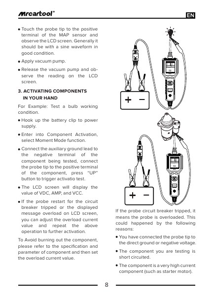
Start a loaded-circuit diagnosis with a diagram, passive voltage-drop measurements, and a known safe load. On positively identified conventional circuits, a combined analyzer can then add basic waveform observation or controlled component activation when the service method calls for it. The MRCARTOOL B550 automotive circuit analyzer is one such multi-function route. Its powered output is never permission to energize a sensor, module, network, SRS line, or any conductor whose function and limits are not proven first.
The goal is not to make the component move by any means available. It is to prove whether power delivery, ground return, command, protection, or the load itself fails under the same condition as the complaint.
Quick answer: A nominal open-circuit voltage does not prove current delivery. Reproduce the complaint, keep the load connected or use an approved substitute, measure power- and ground-side voltage drop, separate command from delivery, and retest the original component.

In this guide
Put the 12-volt reading on trial
Record exactly where the meter leads were placed, whether the connector was attached, and whether the circuit was commanded on. Voltage is a difference between two points; “12 volts at the plug” says little without naming the reference point and load state. Measuring a power terminal to chassis ground may conceal a weak component ground. Back-probing power to the component’s own return tests more of the working path, but still needs the circuit operating.
First confirm the component is actually expected to run. Some motors receive constant power and switched ground; others use relays, pulse-width control, low-side drivers, high-side drivers, or network commands. Door position, engine temperature, pressure protection, and module logic can inhibit operation. If the command is absent by design, a load test at the connector answers the wrong question.
| Reading condition | What the number can say | Missing testimony |
|---|---|---|
| Connector unplugged, circuit on | Potential reaches an open connector | Whether it can deliver current |
| Connector attached, circuit on | Voltage available while the load is present | Which side is losing voltage |
| Power-to-chassis measurement | Power-side potential relative to body | Condition of the component ground path |
| Voltage across a closed connection | Loss at that connection under load | Whether the rest of the circuit is healthy |
Recreate the failure without disturbing it
Before disconnecting, reproduce the complaint and note speed setting, temperature, vibration, key state, module commands, and duty cycle. Inspect without pulling on the harness: discolored plastic, melted fuse cavities, green residue, loose grounds, overheated relay terminals, and previous repairs are high-value clues. Photograph a connector before moving a secondary lock or terminal position assurance device.
Intermittent resistance often disappears when a connector is unplugged and reinserted. If access permits, back-probe with the load connected and use min/max or a scope to capture a dropout. Manipulate one harness area gently while watching the result. Never substitute a higher-rated fuse or bridge a protection device; a blown fuse is evidence of excess current or a short that must be understood.
Define a safe stop point. Starting, steering, brake, restraint, high-current, hybrid/high-voltage, and module-managed circuits may require special equipment and procedures. A test that is ordinary on a two-wire incandescent lamp is not automatically appropriate on an intelligent pump or LED module.
Choose a safe substitute load or live load
The original component is often the most representative load. If it can remain connected safely, measure voltage at its power and ground terminals while it is commanded. If the component is inaccessible or suspected of an internal short, an OEM-specified load or correctly fused substitute can test delivery without risking a known-good part. Choose the load from circuit design and service information—not by matching a bulb found in a drawer.
A high-current load can overheat weak wiring quickly. Keep the test brief, monitor the harness, and use leads and meters rated for the circuit. An incandescent test lamp may be suitable for some conventional feeds but excessive for a delicate controller output. A low-current LED probe can glow through substantial resistance and repeat the same false confidence as an unloaded meter.

Question the power side
With the component commanded and current flowing, measure voltage drop from battery positive to the component’s power terminal. Then divide the path: battery post to terminal, terminal to fuse, across the fuse, relay input to output, connector to connector, and finally the load terminal. The controlling service information provides allowable values; the diagnostic principle is that an unwanted resistance reveals itself as voltage across the bad section under load.
Measure across, not merely at, suspect connections. A fuse can look intact and still have heat-damaged contact tension at its socket. Relay contacts can close audibly but lose significant voltage. A partially broken conductor may behave normally until it bends or warms. Comparing the same points during a known-good command and the failing command is often more useful than applying a universal threshold.
If supply voltage collapses at the battery, the issue is broader than this branch. Check state of charge, battery connections, and charging support as appropriate. If battery voltage stays stable but the loss appears after one connector, the witness has narrowed the scene.
Question the ground side
Move the meter to battery negative and the component ground terminal while the load operates. The displayed voltage is the loss along the return path. Section the route through ground eyelets, splices, body connections, and battery terminals just as you did on the positive side. Do not assume a visually clean bolt makes good electrical contact through paint, sealant, corrosion, or a loose crimp.
A temporary, correctly rated parallel ground can be a diagnostic experiment on an appropriate conventional circuit, but it should not become the repair. If function returns, measure and locate the original loss; then restore the specified conductor, terminal, attachment, and corrosion protection. Never add a bypass ground to a monitored or controlled circuit without understanding how the module measures it.
| Trial outcome | Stronger interpretation | Next controlled step |
|---|---|---|
| Power-side drop high, ground-side drop low | Resistance is concentrated in supply path | Divide fuse/relay/connectors under load |
| Ground-side drop high | Return path cannot carry load current | Divide grounds and splices |
| Both paths low, correct command present | Load may be open, seized, or internally controlled | Verify current and component procedure |
| Voltage disappears before command | Control logic or protection may be withholding operation | Check inputs, codes, and relay/driver command |
Separate command from current delivery
Control and delivery are different witnesses. A scan tool can show that the module requested blower operation, yet the relay, wiring, ground, or motor can fail. Conversely, the wiring can carry current perfectly while a pressure switch, temperature input, network message, or protection strategy prevents the command. Use the diagram to identify where a low-current command ends and the high-current path begins.
If a relay is removable, confirm terminal identification and the specified test before swapping. Identical housings do not guarantee identical internal suppression or pin arrangement. On solid-state drivers, do not use a heavy test lamp or apply external power. Observe command, output, and fault status with the approved load connected. A driver that shuts down may be protecting itself from excess current rather than failing to supply current.
Use current and waveform only when they answer a question
Current can separate a seized or overloaded motor from a high-resistance supply. A current ramp can reveal commutator or mechanical behavior, and a scope can catch a repeating dropout. But current measurement introduces its own risks: opening a circuit, choosing the wrong jack, exceeding a meter fuse, or placing a clamp around both conductors can create false or dangerous results.
Write the question first. “Does this motor draw current when commanded?” may need only a correctly ranged clamp. “Do commutator segments repeat evenly?” needs suitable bandwidth, sampling, and interpretation. “Is a PWM driver switching?” requires an appropriate scope reference and probe connection. A basic waveform function can confirm presence and gross shape; a dedicated automotive scope is the stronger route for deep capture and multi-channel correlation.
Compare passive and powered tool routes
There is no defensible public model-level sales ranking for this niche, so compare complete working methods. Fluke 88V and similar professional meters emphasize passive, rugged measurement. Power Probe and TOPDON offer powered circuit-test routes. Klein and other general meters can handle bounded voltage-drop work if their ratings, leads, and protection suit automotive use. PicoScope adds specialist waveform evidence. A fused jumper and known-good load remain valid low-complexity tools when the service method calls for them.
| Route | Strength | Critical limitation |
|---|---|---|
| Passive multimeter | Lowest risk for voltage-drop localization | Does not activate a load |
| Fused substitute load | Proves delivery more honestly than open-circuit voltage | Must be correctly sized and allowed |
| Powered circuit analyzer | Fast conventional component activation and combined tests | Misuse can damage electronics |
| Automotive scope/current clamp | Captures timing, PWM, ramps, and intermittent events | Higher skill and equipment band |
| Outsource/no-buy | Sensible for rare safety-critical or complex driver cases | Turnaround and outside dependency |
If the unanswered question is simply where voltage is lost under load, start with a passive meter and the component or a correctly sized substitute load. A combined circuit analyzer becomes useful only after the diagram identifies a conventional circuit and the next question genuinely requires activation or a basic waveform. The B550 combines those functions in one instrument, which can reduce tool changes during repeated low-voltage work while keeping passive tests available first.
Choose a disciplined passive meter and a stronger automotive scope when the work centers on sensors, module controls, networks, PWM, or multi-channel timing. Use a fused jumper only when the service method permits it, and use established professional systems when calibration traceability, guided tests, or local service control the job. The correct route is determined by the evidence missing from the circuit—not by the fact that a tool can send power.
Plan the repair before bypassing anything
If a temporary fused feed or ground proves that the original path cannot carry current, stop and write what the bypass did and did not include. A feed placed directly at the motor may bypass the fuse, relay, current monitoring, speed controller, and thermal protection. It can show that a conventional motor is capable of turning, but it cannot show that the vehicle should command it or that every bypassed device is faulty.
The permanent repair must restore conductor gauge, terminal material and tension, sealing, routing, strain relief, fuse rating, and controller protection. Crimp quality matters more than a shiny connector shell. Use the specified terminal service kit or replace the approved harness section; twisting wires together or fitting an oversized universal terminal changes resistance and corrosion behavior.
When heat becomes evidence
A thermal imager or temperature probe can locate a connection that warms under load, but heat follows both resistance and current. A hot terminal may be the restriction; a hot motor cable may simply be carrying excessive current from a seized load. Compare matched points and pair temperature with voltage drop/current. Never reach into a live fan or treat the absence of visible heat as proof of a healthy intermittent connection.
Retest the original load
After repair, remove diagnostic bypasses and substitute loads. Reconnect the original component, restore clips and seals, install the specified protection device, and reproduce the exact speed, temperature, duty cycle, and duration that exposed the failure. Measure voltage drop on both sides again while the load works. Confirm current behavior if it was part of the diagnosis and scan for related driver or network faults.
The final statement should name the failed path and evidence: “Open-circuit voltage was present, but the loaded relay-output connection lost most of the available voltage; terminal repair restored low loss and normal motor operation through all speeds.” That survives cross-examination. “It had 12 volts, so we powered it and it ran” does not explain why the vehicle circuit failed or whether the controller and protections remain intact.
Objections from the service bay
The motor runs from a jumper—doesn’t that prove the wiring is bad? It proves the motor can run under that temporary feed and condition. The original command, ground, load current, speed controller, and mechanical load may still need separation. Record exactly which parts the jumper bypassed.
Can I load every 12 V feed with the same test lamp? No. A conventional relay-fed lamp circuit and a current-limited module output tolerate different loads. Select the test load from the diagram and service method. Unknown, network, sensor, and SRS circuits are excluded.
Why not just measure resistance? Static resistance can change when a terminal heats, vibrates, or carries current, and parallel module paths can distort an ohmmeter reading. Loaded voltage drop observes the circuit doing its actual job and often localizes the loss more honestly.









Comments 0
Questions, fixes, and real-world diagnostic notes from readers.
Be the first to share a diagnostic result or ask a follow-up question.