
Steering Wheel Still Crooked After an Alignment? Audit the Job Before Adjusting Again

Why Is The Steering Wheel Still Crooked?
A steering wheel that remains crooked after an alignment is not a cosmetic detail to be hidden with one more tie-rod turn. It is a comeback with at least three references that may disagree: the steering wheel center, the vehicle’s geometric thrust line, and the road direction the driver experiences. The job is to find which reference moved—and why.
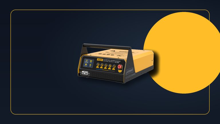
A repeatable four-wheel geometry measurement is the right foundation for that audit. The AUTOOL XC505 3D wheel aligner is one route for recording toe, camber, caster, thrust angle and before/after results. It cannot reveal tire conicity, correct loose suspension, hold a wheel that was allowed to move during adjustment, or decide whether a particular vehicle requires steering-angle calibration.
Treat the second visit like a quality-control investigation. Preserve the first printout, measure the visible steering-wheel offset, and drive the same suitable route before anyone loosens an adjuster. A fresh measurement without the original evidence can make a setup error look like a vehicle fault.
Quick answer: Separate steering-wheel center, vehicle thrust line, and road pull. Audit tires, alignment setup, before/after geometry, wheel holding, and model-specific steering-angle calibration before making another adjustment.

In this guide
- Open the comeback with three centers
- Recreate the road complaint
- Audit setup before touching an adjuster
- Read the printout as a geometry story
- Center the wheel while toe is adjusted
- Treat steering-angle zero as a separate operation
- Investigate a car that still pulls with a level wheel
- Close the job with matched evidence
Open the comeback with three centers
Ask the driver to separate “the car pulls” from “the wheel is crooked.” A vehicle can travel straight while the wheel sits off-center. It can also require steady steering force because of road crown or tire force even though the steering wheel is geometrically centered. Those are different complaints and may coexist.
Record where the wheel sits on a flat-looking road in both directions, how much hand force is needed, whether the wheel returns differently after left and right turns, and whether the condition began immediately after the alignment. Note any tire rotation, steering, suspension, collision, curb-strike or ride-height work.
The three references are:
| Reference | Evidence | What disagreement suggests |
|---|---|---|
| steering wheel center | spoke position and measured rim offset | wheel moved during adjustment, steering linkage asymmetry, or centering error |
| vehicle thrust line | rear toe and thrust angle | vehicle may travel relative to a rear-generated direction |
| road direction | controlled two-way road test | crown, tire force, brake drag, wind, or chassis effects may mimic alignment pull |
Do not use a sloped parking-lot lane as the final road reference. The goal is not to find a perfectly level public road; it is to compare direction, lane, speed and vehicle load consistently.
Recreate the road complaint
Set tire pressures to the vehicle specification and inspect size, construction, wear, damage and position. Remove unusual cargo and confirm normal ride height. A low tire, mismatched tire, shifted belt or strong conicity can produce steering force that an alignment printout will not explain.
Drive with the steering wheel held at the position the driver calls straight, then allow only a light safe grip and observe the vehicle tendency. Repeat on the same stretch in the opposite direction when safe. If the pull changes with road direction but wheel offset remains, road crown deserves more weight. If the pull remains with the vehicle, tire and chassis branches stay open.
Use a centering tape or another repeatable reference to record how far the wheel rim is displaced. “A little left” is difficult to compare after the next adjustment. A photo taken square to the wheel and a measured reference make the before/after discussion objective.
Audit setup before touching an adjuster
An alignment machine reports the geometry it sees through its targets and setup. Verify calibration status, lift and turn-plate condition, target/clamp seating, correct vehicle selection, wheel and tire runout compensation, tire pressure, ride height, loading instructions and any required suspension settling.
Inspect wheel bearings, ball joints, tie rods, control-arm bushings, strut mounts, steering rack attachment and damaged wheels before adjustment. Movement that changes under load can let the machine display an acceptable static number while the road position shifts. Repair excessive play first; do not align around it.
Confirm that the rear axle was measured and that rear toe and thrust angle are part of the story. A front-only toe correction can leave the wheel centered relative to the front rack but not relative to the vehicle’s path. On adjustable rear systems, rear geometry is normally established before the final front toe procedure, subject to service information.
Read the printout as a geometry story
Do not stop at green and red boxes. Compare individual left and right values, total toe, cross values, thrust angle and the pattern between the first and current measurements. A value inside a broad display tolerance may still help explain why the wheel moved if it is not balanced as the procedure expects.
Ask four questions:
- Did the rear thrust reference change or remain offset?
- Did total front toe land correctly while the two individual toe values split around a crooked wheel?
- Did camber or caster asymmetry suggest a pull branch that toe cannot repair?
- Did any reading change after rolling, steering, settling or re-compensation?
If the repeat measurement changes materially without an adjustment, investigate setup, loose parts, ride height and wheel clamping. Repeatability is part of the diagnosis. Printing a second green sheet does not explain a first sheet that cannot be reproduced.
Center the wheel while toe is adjusted
Place the steering system in the manufacturer-defined center, not merely where the spokes look level. Confirm lock-to-lock symmetry only by an approved method and account for vehicles with indexed shafts, variable-ratio steering or electronic center procedures. Never remove and reposition a steering wheel simply to hide a linkage or alignment error unless service information specifically calls for that repair.
With the wheel held securely, adjust toe using the specified sequence and keep the steering gear from walking off center. Adjusting only one side to level the spokes can change total toe or create unequal tie-rod geometry. On many systems, coordinated changes maintain total toe while moving the wheel reference, but the actual procedure controls.
After tightening, release the holder, settle and steer the vehicle as required, then remeasure. Watch the wheel during tightening: a wrench, boot wind-up or clamp movement can shift the final position after the live screen looked correct.
Treat steering-angle zero as a separate operation
The steering-angle sensor reports an electronic reference used by stability, steering and driver-assistance systems. A mechanical wheel can be straight while the stored sensor value is not zero, and a zeroed sensor cannot make crooked mechanical geometry straight.
Check current service information to learn whether calibration is required after alignment, steering work, battery events or module replacement. Confirm prerequisites such as level surface, wheel position, voltage, tire pressure and fault status. Read the value before and after, save any codes, and do not erase evidence simply to turn off a warning.
If the sensor refuses to calibrate, return to the basics: mechanical center, clock spring position, rack indexing, wiring, module communication and installed steering components. Repeating a calibration command cannot compensate for an incorrectly assembled column or rack.
Investigate a car that still pulls with a level wheel
Once the wheel is level and geometry repeats, a remaining pull should be investigated on its own merits. Compare front tire positions using an approved diagnostic swap when tire construction and direction permit. Inspect brake temperature and release, wheel-bearing drag, ride height, damaged springs, shifted subframes and body/chassis reference dimensions.
Electric power steering can also apply unwanted assist because of torque-sensor, calibration, supply-voltage or control faults. Preserve codes and live data, and use the manufacturer’s centering or pull-drift procedure. Do not add unequal toe to cancel an electronic or tire-force problem; it may trade a pull for tire wear and leave the real fault untouched.
The steering wheel position after a repair should not depend on which lane was used for the last test. If a shop offers road-crown compensation, that choice should be deliberate, documented and consistent with manufacturer guidance—not an unexplained off-center wheel.
Close the job with matched evidence
Attach both the original and final printouts to the work order. Add the steering-wheel offset before and after, tire findings, parts inspected or repaired, calibration result, road-test route and direction, and any warning-lamp status. A printout answers geometry; the road test answers behavior.
Run the same two-way route at the same tire pressures and normal load. The wheel should return to the recorded center, the vehicle should respond predictably, and readings should remain repeatable after settling. If the car still requires steering force, open a pull diagnosis rather than rotating the wheel away from center.
The comeback is closed only when all three references agree closely enough for the vehicle: the wheel is centered, the thrust/geometry record is correct, and the road behavior has an explained result. That is a completed alignment—not just a screen full of green boxes.









Comments 0
Questions, fixes, and real-world diagnostic notes from readers.
Be the first to share a diagnostic result or ask a follow-up question.