
P0420 Does Not Automatically Mean a New Catalytic Converter—Build the Case First

Build The Case Before Replacement
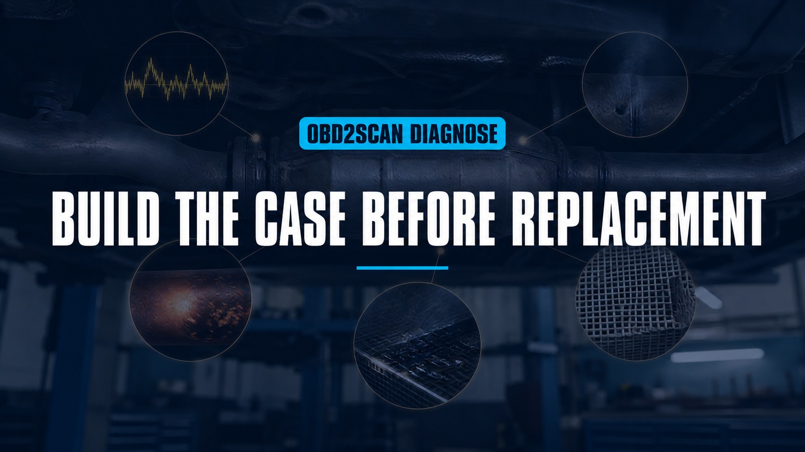
P0420 means the control system has judged catalyst efficiency below its expected threshold for a monitored condition. It does not say the converter is physically empty, the rear oxygen sensor is automatically bad, or a new converter will survive whatever caused the first one to fail. Build the replacement case in five gates.
Visual access can strengthen the final gate when the substrate is reachable and cool. A compact articulating camera such as the MRCARTOOL N180 borescope can document cracking, melting, deposits or displacement without turning that observation into an efficiency measurement. A normal-looking brick can still convert poorly, and a damaged brick still needs an upstream cause.
Do not clear the code before saving the evidence. Catalyst monitors run only under particular conditions, so the freeze frame, companion codes and monitor history may be more useful than a quick idle test. Use current service information and emissions rules for the exact vehicle.
Quick answer: Require five gates before converter replacement: complete code/software context, exhaust and sensor integrity, stable combustion, contamination/heat causes, and an OEM converter test plus bounded physical inspection.
In this guide
Gate one: preserve the complete code context
Read all modules and save confirmed, pending and permanent codes, freeze-frame data, readiness status, monitor results where supported, mileage since clearing and software/calibration information. A P0420 accompanied by misfire, fuel-pressure, air-metering, oxygen-sensor, coolant-temperature or exhaust-system faults is a different case from an isolated efficiency code on a stable engine.
Confirm the bank. On multi-bank engines, identify cylinder numbering and converter layout from service information; guessing “left” from the driver’s seat creates avoidable replacement errors. Check whether an upstream and downstream converter, close-coupled catalyst, particulate filter or combined assembly changes what Bank 1 monitor actually observes.
Look for applicable manufacturer bulletins or calibration updates. Do not install software simply because a code exists, but do not condemn hardware using monitor logic that the manufacturer has formally revised. If codes were recently cleared, allow the approved monitor process rather than assuming “not ready” means passed.
Gate two: clear leaks and sensor circuits
Inspect exhaust leaks from the cylinder head through and beyond the monitored catalyst, paying special attention to flex sections, flanges, welds and sensor bungs. Pulses can draw oxygen into a small leak and distort a sensor signal without producing a loud continuous noise. A smoke or low-pressure leak test must stay within exhaust-system and equipment limits.
Inspect both sensor harnesses for heat damage, oil, water, contact with the exhaust, pin fit and disturbed connectors. Verify heater circuits, supply and ground by the wiring diagram. An oxygen or air-fuel sensor should be judged by its correct type and diagnostic procedure; switching behavior and voltage conventions differ.
Do not replace the downstream sensor merely because its graph resembles the upstream signal. Similarity may support the monitor’s concern, but a sensor bias, exhaust leak, test condition and actual catalyst behavior still need separation. Conversely, a flat rear signal can reflect a sensor or circuit problem rather than a perfect converter.
Gate three: prove the engine is not poisoning the test
Review fuel control under the load and speed captured in freeze frame, not only at idle. Check short- and long-term correction where meaningful, mass-airflow or load plausibility, fuel pressure, injector balance, purge behavior, coolant temperature, misfire counters and ignition condition. A mixture fault can reduce conversion during the monitor and damage the catalyst over time.
Investigate oil and coolant consumption. Blue smoke, oily plugs, rising oil use, coolant loss, white deposits or sweet exhaust odor can point to contamination. Silicone sealants, phosphorus from oil additives, leaded fuel and other substances can poison catalyst surfaces. Correcting the converter without correcting consumption invites a repeat failure.
Look for overheating causes such as sustained misfire, leaking injectors, incorrect timing or air injection faults where equipped. A glowing or rattling converter is not a reason to continue the test. Stop the engine and diagnose the heat source.
Gate four: identify contamination and heat
Build a converter history: original or replacement part, mileage, collision or underbody impact, prior engine failure, rich running, oil burning, coolant leak and exhaust repair. Confirm the installed converter is approved for the vehicle and jurisdiction. A physically similar low-capacity unit may not meet the monitor or legal application.
Temperature measurements can show that heat is being generated or lost, but an inlet/outlet difference is load- and condition-dependent. An unloaded idle temperature comparison is not a universal efficiency test. Backpressure can identify a flow restriction, yet a converter can have low backpressure and poor chemical conversion—or high backpressure from a downstream muffler.
Rattles, debris at an outlet, localized red heat, impact marks and displaced shields are physical clues. Document them before disassembly. Do not hammer the shell or drill a test hole; emissions components and hot surfaces require approved access.
Gate five: test and inspect the converter
Use the manufacturer’s catalyst test plan. It may compare upstream and downstream sensor response under a controlled drive, oxygen-storage behavior, mode-specific data, temperature, monitor ratios or a service-bay routine. Avoid universal sensor-voltage or fuel-trim thresholds copied from another application.
Confirm the engine and exhaust are fully in the temperature window required by that plan. A cold catalyst, prolonged idle, deceleration fuel cut or a hybrid engine that repeatedly stops can produce graphs that look persuasive but do not represent the monitor condition. Save time, load and temperature with every capture.
For visual inspection, cool the exhaust fully, remove only an approved sensor or connection, and keep the probe clear of sharp edges. Confirm the camera head fits without force and cannot detach. Look at the accessible face and side angles for melted passages, cracking, a shifted brick, impact, heavy deposits or missing material. Save orientation-labeled images.
What the camera cannot see matters. The opposite face may be damaged, internal sections may be obscured, and chemical washcoat degradation can be invisible. Therefore “looks intact” does not pass the converter; it simply removes some physical failure modes from the evidence set.
Build the replacement decision
Use a gate sheet:
| Gate | Pass condition |
|---|---|
| Code context | correct bank, monitor condition, no unaddressed higher-priority faults |
| Leaks/sensors | exhaust boundary and sensor circuits proven |
| Combustion | fuel control, misfire and temperature stable |
| Contamination | oil/coolant/overheat cause corrected or ruled out |
| Converter | OEM test supports low efficiency and/or physical damage is documented |
A replacement case is strong when all five gates point in one direction. If upstream faults remain, repair and rerun the monitor first. If the substrate is broken or melted, replacement may be physically necessary, but the engine cause still belongs on the same work order.
Choose a converter by exact application, emissions certification, engine family and installation requirements—not shell dimensions alone. Premium OEM and certified professional-grade assemblies may offer the strongest fit and monitor compatibility; lower-cost alternatives must still meet local regulation and application. No tool can make an unapproved converter legal.
Verify the upstream cause stays gone
After repair, confirm no exhaust leaks, correct sensor installation and wiring, stable fuel control, zero active misfire, and resolved oil/coolant contamination. Complete the prescribed drive cycle or monitor routine without unsafe driving. Readiness must set through normal logic; forcing repeated high-load driving is not a substitute.
The repair passes when P0420 does not return under its monitor conditions, relevant mode data is acceptable, and the upstream fault remains absent. Keep the five-gate record and images. They explain why the converter was replaced—and, more importantly, why the new one has a chance to last.




Comments 0
Questions, fixes, and real-world diagnostic notes from readers.
Be the first to share a diagnostic result or ask a follow-up question.