
A Vehicle Module Fails Hot and Works Again Cold? Build a Board-Level Evidence Trail

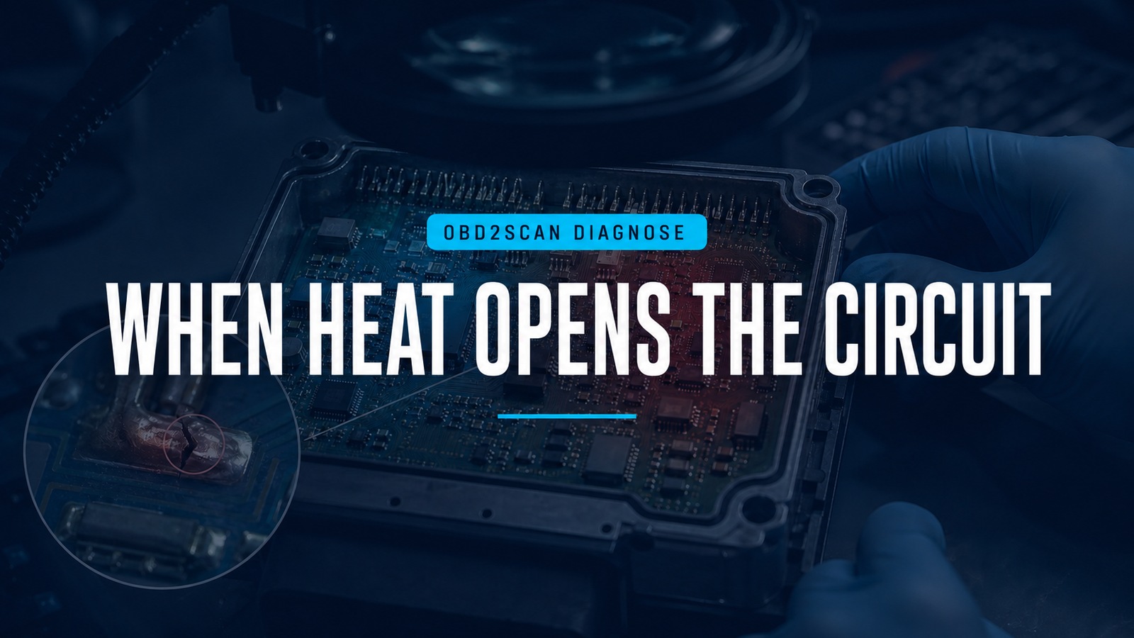
When Heat Opens The Circuit
A module that fails hot and returns after cooling invites a seductive shortcut: open the case, find the hottest component, and replace it. Heat dependence is useful evidence, but the hottest part may be operating normally while a connector, power feed, cracked joint, regulator, capacitor, network load, or software state creates the symptom.
Board-level measurement belongs late in the chain and only on de-energized parts. Fine probes such as the AUTOOL DM103 digital LCR tweezer can compare accessible passive components at supported test frequencies after capacitors are fully discharged. They cannot diagnose powered logic, firmware, network traffic, or a complete module in circuit.
Approach this as a thermal-fault autopsy. Photograph every state, change one temperature zone at a time, and distinguish observation from verdict. Airbag, braking, steering, immobilizer and other safety/security modules often belong with approved remanufacturing or replacement specialists rather than experimental board repair.
Quick answer: Prove module power, ground, network and load first. Then use a controlled thermal map, visual inspection and de-energized component comparisons to separate a passive part, solder joint, trace or external-system fault.
In this guide
Prove the heat-linked failure at vehicle level
Capture the symptom before removing the module. Record ambient and cabin temperature, time from cold start to failure, vibration and load, which functions disappear, warning messages, all-module DTCs, network communication status, and recovery time after shutdown. Determine whether cooling the cabin, the connector, the module case or an upstream power component changes the interval.
Measure module supply and ground under load during the healthy and failed states. A corroded splice, relay, fuse terminal or ground can increase resistance with heat and make the module appear internally unstable. Scope or log the supply if the event is brief. Verify wake, ignition and communication lines by the vehicle wiring diagram rather than assuming one constant battery feed is enough.
Check whether other modules on the same network fail simultaneously. A shorted node, bus termination issue, gateway state or low system voltage may remove communication with a perfectly healthy target. If a controlled substitute or bypass is permitted, use it only to answer a defined boundary question.
Decide whether the board should be opened
Confirm legal, security and service consequences. Opening a sealed or potted module may destroy its moisture protection, warranty or exchange value. Replacement can require programming, coding, immobilizer work, calibration or data transfer. Safety-critical units may contain stored energy or firing circuits even after vehicle power is removed.
Obtain the connector pinout, case-opening method, ESD precautions and any remanufacturer policy. Disconnect power by the vehicle procedure and wait the specified discharge time. Use an ESD-safe bench, wrist strap and grounded tools appropriate to the assembly. Do not apply heat or solvent around undeployed restraint hardware, high-voltage systems, batteries, pyrotechnic devices or unknown conformal coatings.
If the fault can be proved externally and the module is not designed for field repair, stop. A good investigation sometimes ends with a documented remanufacture decision rather than a soldering iron.
Run the cold visual autopsy
Before cleaning, photograph both sides at high resolution. Look for liquid tracks, corrosion blooms, cracked or dull joints, lifted pads, darkened board areas, swollen or vented electrolytic capacitors, leaking electrolyte, fractured heavy components, damaged connector pins, rubbed conformal coating and previous repair. Smell can identify a burnt zone, but avoid inhaling fumes or touching residues.
Use angled light and magnification. Ring cracks around connector or relay pins may hide when viewed straight down. Heavy transformers, inductors, power resistors and connectors flex solder joints under vibration. Thermal cycling also stresses dissimilar materials, so a joint may open only after expansion even though it looks acceptable cold.
Do not equate a brown adhesive with a burn or a manufacturing residue with corrosion. Compare repeated components and, if available, a known-good board revision. Note every observation on a map before measuring; otherwise the first odd reading will rewrite the visual story.
Localize heat without cooking the evidence
Reproduce the fault with the least thermal stress. A thermal camera can show zones but reflected surfaces and emissivity can mislead. Controlled warm air, a temperature chamber, or carefully placed local heat can narrow the area. Monitor board temperature with an independent sensor and remain below component, coating and case limits.
Heat one zone, observe the exact vehicle-level or bench symptom, allow full recovery, then repeat. Cooling spray can be useful when approved, but condensation and rapid thermal shock can create new faults. Never spray a powered high-voltage or ignition source. A component that responds to cooling may be the source, a nearby joint, or merely transferring stress to the board.
Record a thermal timeline: start temperature, failure temperature, function lost, supply current, output state and recovery. Repeatability matters more than dramatic temperature. If the fault appears only under vehicle load, a powered bench test without the real loads may never reproduce it safely.
Measure passive parts in the right state
Remove power, discharge capacitors fully, and verify zero energy before using an LCR instrument. Identify the component and expected value from markings, schematic, datasheet or a matched known-good part. Select a test frequency and mode suited to the component. Capacitance, impedance, ESR, dissipation factor and quality factor are related but not interchangeable.
In-circuit readings include every parallel path. A low resistance may be a neighboring network rather than a shorted capacitor; an apparently high capacitance may be several devices together. Compare symmetrical channels first, then lift a lead or remove the component only when the board and repair process support it. Preserve polarity and orientation.
Temperature changes component values naturally. Compare the observed drift with specifications instead of calling any movement defective. For intermittent joints, four-wire resistance, continuity under controlled flex, microscopy or X-ray may be more relevant than capacitance. For logic and communication faults, an oscilloscope, current-limited supply and protocol knowledge may be required.
Separate component, joint, trace and system causes
Build an evidence ledger:
| Candidate | Evidence for | Evidence still needed |
|---|---|---|
| Passive component | value/ESR changes outside spec with heat | isolated confirmation and replacement retest |
| Solder joint | visible ring, thermal/mechanical repeatability | continuity or rework by controlled process |
| Trace/via | localized open or corrosion | end-to-end measurement and layer assessment |
| External circuit | supply/network/load changes with symptom | vehicle-side voltage, waveform or load isolation |
Do not “reflow the whole board.” Uncontrolled heat can damage plastics, semiconductors, multilayer vias and conformal coating while temporarily hiding the original fault. Use the correct alloy, flux, temperature profile and cleaning method for a proven joint. Replace a component with the exact electrical, temperature, tolerance, ESR, voltage and package requirements—not merely the same printed capacitance.
After any board work, inspect for bridges, lifted pads, polarity and residue. Current-limit the first power-up where the approved bench procedure permits. A repaired passive value is not yet proof that the vehicle symptom is gone.
Close with a controlled heat-cycle retest
Reassemble sealing and thermal interfaces as designed. In the vehicle, repeat the original warm-up time, electrical loads, vibration condition and network capture. Confirm stable power and ground, normal communication, no returning DTCs and correct output through multiple hot/cold cycles.
Document the component or joint evidence, measurements before and after, board revision, repair materials, programming state and environmental seal. If the failure cannot be reproduced safely or the repair is not repeatable, label the module unresolved and use an approved replacement or remanufacture route. The goal of the autopsy is a defensible repair—not merely a board that survived one warm afternoon.









Comments 0
Questions, fixes, and real-world diagnostic notes from readers.
Be the first to share a diagnostic result or ask a follow-up question.