
Programming Supply Looks Stable but the Session Drops? Measure at the Vehicle

Measure Where The Module Lives
The support unit’s display reports the voltage at its own sensing point. The module experiences what survives clamps, cable length, contact resistance, battery behavior, grounds, vehicle loads, and time. A stable number at the source can coexist with a reset at the car.
When a programming session fails with resets or voltage-related symptoms, the needed equipment is a support unit that can deliver the procedure’s required voltage and current continuously—not merely display a stable number at its own terminals. The AUTOOL EM355 programming power supply is one fixed/adjustable support route, but its mode is only useful after the exact OEM or authorized procedure defines the target, connection, load margin, and recovery plan. Measure at the vehicle while the load is present, because source-display voltage does not prove delivered voltage.
Programming and coding can immobilize a vehicle or damage modules when interrupted. Freeze the change process before another attempt. Preserve logs, understand the recovery path, and measure where the module lives.
Quick answer: Do not retry immediately. Preserve programming logs and recovery state, prove battery condition and delivered voltage at the vehicle under representative load, control avoidable loads, match the exact authorized support mode, and separate power loss from network or software loss.

In this guide
- Freeze the session before another retry
- Separate source voltage from delivered voltage
- Verify the battery and connection path
- Record voltage at the vehicle under load
- Control avoidable vehicle loads
- Match mode and target to the service procedure
- Separate power loss from network or software loss
- Compare support-unit routes
Freeze the session before another retry
Save the programming application log, error text, module address, software part numbers, elapsed stage, battery-support settings, key state, network interface details, and any recovery instruction. Do not clear faults, cycle the ignition repeatedly, disconnect the battery, or retry because the progress bar nearly finished. A bootloader/recovery state may require a precise sequence.
Check whether the OEM platform calls the operation recoverable, resumable, or dealer/support-assisted. Maintain the vehicle state required by that instruction. If a safety-critical controller, immobilizer, gateway, or high-voltage system is involved, escalate early. The cost of professional recovery can be far lower than turning an incomplete flash into an unrecoverable module.
| Evidence at failure | What it can narrow | What it cannot prove |
|---|---|---|
| Supply display stayed stable | Source did not report a local voltage change | Battery-post or module voltage stayed stable |
| Laptop lost connection | Data path or power was interrupted | Which side caused it |
| Several modules reset together | Shared power/network event likely | Support unit is solely responsible |
| Only target stopped responding | Target path/state/software deserves focus | Module hardware is permanently failed |
Separate source voltage from delivered voltage
Treat the power chain as nodes: wall source or input supply, support-unit terminals, clamps, battery posts, vehicle distribution, grounds, and the target module. Voltage measured at one node is not automatically present at the next under changing current. Contact resistance can create a brief drop exactly when pumps, fans, relays, or the programming routine changes load.
Use correctly rated, independently verified measurement equipment at the battery posts during a controlled non-programming load or authorized diagnostic setup. If possible, log min/max or waveform behavior rather than watching a slow display. Never probe target module pins or repeat programming merely to capture a drop unless the recovery procedure makes that safe.
Verify the battery and connection path
Identify battery chemistry, state of charge, condition, and the vehicle manufacturer’s support method. A weak battery can absorb or release current unpredictably while appearing acceptable at rest. Inspect posts, terminals, remote jump points, grounds, pyrotechnic disconnects, and sensor placement. Connect support equipment only at the specified points and in the specified order.
Clean, fully engaged clamps on conductive surfaces matter. A clamp on a thin accessory stud, painted bracket, or loose terminal can show voltage but create loss under demand. Secure cables against movement and keep them away from fans, belts, exhaust, and hood closure. Confirm AC input stability and ventilation for the supply.
Record voltage at the vehicle under load
Before risking another programming event, create a safe load profile using the procedure’s checks or controllable vehicle loads. Measure at battery posts and, if authorized, across positive and ground delivery paths. Record starting voltage, current indicated by the support unit, post voltage, voltage drop, load transitions, and temperature. The exact OEM target and allowed variation control; do not import one “programming voltage” from another brand.
A post-voltage dip with a steady supply display suggests delivery, sensing, response time, current limit, or battery interaction. Both displays dipping may point toward capacity, input power, mode, or load. Stable battery-post voltage during a communication loss directs attention toward interface, network, software, sleep/wake, or the target branch. This test changes the next decision without writing another module.
Control avoidable vehicle loads
Follow the service checklist for lights, HVAC, heated glass/seats, audio, chargers, doors, and key location. Disable only what the procedure authorizes. Some fans or pumps activate automatically and must not be defeated; instead, the support equipment must meet documented demand. Keep the laptop powered and prevent operating-system sleep, forced updates, unstable wireless links, and cable movement.
Close or latch doors/hood only as directed, because latch state can wake networks or trigger loads. Remove aftermarket accessories when authorized and documented. Monitor support-unit temperature and ventilation. A change-control log should list every controlled variable so the next attempt is repeatable rather than hopeful.
Match mode and target to the service procedure
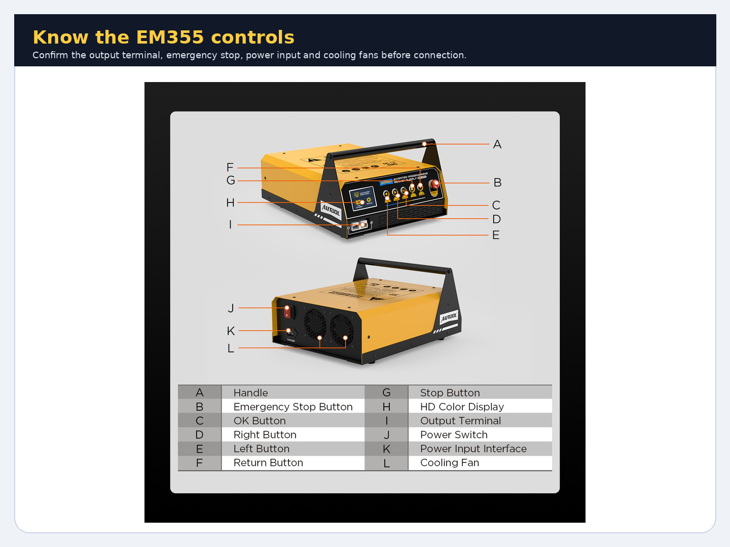
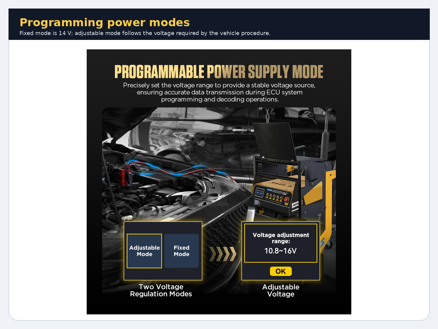
The EM355 manual’s fixed and adjustable modes make it adaptable, but the procedure chooses the target. Confirm whether the operation calls for power-supply mode, a specific voltage window, minimum current capacity, ripple requirement, or no charger connection at all. Verify polarity before connection and understand the unit’s emergency-stop and protection behavior without testing those protections during programming.
Do not assume higher voltage is safer. Excess voltage can trigger module protection or damage; low voltage can reset modules; a charging algorithm may vary voltage when a stable supply is required. Confirm current-limit settings and whether the unit’s output is appropriate for the vehicle battery chemistry and network. If any requirement cannot be documented, stop.
| Control item | Lock before retry | Evidence retained |
|---|---|---|
| Support mode/target | Exact authorized value and capacity | Unit setting/photo, manual revision |
| Connection | Specified posts, clean secure clamps | Voltage-drop/load record |
| Vehicle state | Key, doors, loads, network sleep/wake | Preflight checklist |
| Data path | Approved interface, cable/network, software | Version and application log |
| Recovery | Resume/recover/escalate sequence | OEM instruction/case reference |
Separate power loss from network or software loss
Correlate timestamps. If battery-post voltage and interface power remain stable through the failure, investigate USB/Ethernet/Wi-Fi stability, VCI firmware, gateway authorization, module communication, software package, server session, and vehicle state. If several modules log undervoltage or reset at the same moment, revisit delivered power. A single target dropping at the erase/write boundary can be software/state-specific.
Avoid causal language based on sequence alone. A module reset may cause network loss, or network loss may make the application report a voltage-related generic error. Use logs from the vehicle, VCI, application, and independent voltage capture on one time line. Escalate with those artifacts rather than repeatedly consuming write cycles.
Compare support-unit routes
No auditable model-level sales-share ranking exists for this specialist niche. Midtronics, GYS, Deutronic, Fronius, and Clore/SOLAR offer professional support/charger routes with different current capacity, service, and workflow integration. A conventional charger may be inappropriate for programming. A lab supply may lack automotive protections or battery-management behavior. OEM-approved lists and local support can outweigh feature count.
| Route | Best fit | Tradeoff |
|---|---|---|
| Balanced programming support unit | Independent shops with documented voltage/current needs | Must be matched to each procedure |
| OEM-approved professional supply | High programming volume, support and recovery | Higher equipment band |
| Conventional smart charger | Battery maintenance/charging when permitted | Algorithm may not provide programming stability |
| Lab supply | Controlled electronics bench work | Vehicle protection, cables, capacity may be unsuitable |
| Outsource/no-buy | Rare, security-critical, or high-risk flashes | Less in-house speed, lower brick risk |
If the missing capability is controlled continuous support at a documented target, choose a programming supply whose output, protection, duty, cables, and connectors meet that procedure. The EM355 provides fixed and adjustable support modes for this role, but the decision still comes from voltage measured at the battery or approved vehicle point while the session is under load. A stable source display cannot excuse weak clamps, cable drop, battery behavior, or a poor ground path.
Use an OEM-listed Deutronic, Fronius, Midtronics, GYS, or equivalent route when approval status, higher continuous demand, calibration, local service, or fleet records are mandatory. Outsource the session when the shop lacks a supported interface, subscription, recovery path, or compliant supply. The right unit is the one that satisfies the programming procedure at the vehicle, not the one with the most modes on its face.
Use a dry-run without writing
Where the OEM workflow permits, perform every non-writing step first: identify the vehicle and target, verify current software, authenticate, confirm subscription/server access, check storage and laptop power, establish VCI connection, read existing data, and test support voltage under representative loads. Stop before erase/write. A dry-run cannot guarantee the flash, but it can remove preventable failures without putting a module in transition.
Time the support-unit response to load changes and compare its display with an independent post measurement. If fans or pumps are expected during the real operation, include an authorized comparable load. Confirm cables cannot be kicked, hood/doors will remain in the required state, and no shop timer will cut wall power.
Define the abort boundary before starting
Some warnings justify stopping before programming begins; once erase/write starts, interruption can be worse than continuing. The service application controls. Write down who has authority to stop, which indicators are monitored, and how an emergency is handled. The EM355 has documented protection/emergency features, but pressing a stop during a module write is an emergency action, not a routine response to anxiety.
Treat support capacity as a duty-cycle question
Peak current language is not the same as sustained current under a long session. Compare continuous capacity, thermal environment, cable drop, battery interaction, and vehicle load profile with the authorized requirement. If support approaches a limit during the dry-run, a higher-band professional supply is cheaper than testing the margin during programming.
Afterward, let the supply cool and inspect clamps/cables. Heat, damaged insulation, or loosened connections invalidate the next job even if the prior session completed.
Build a safe go/no-go record
Complete a written preflight: battery condition, verified post voltage under representative load, allowable path loss, secured leads, correct mode, controlled loads, approved software/interface, stable laptop/network, target identification, and recovery plan. Have technical-support contact and time window available. Then perform only the authorized recovery or retry, without adding another experiment mid-session.
After success, verify module identity/software, clear only appropriate test history, perform required coding/adaptations, scan all modules, and test vehicle functions safely. Archive the voltage log beside the application log. If recovery is not authorized or evidence remains ambiguous, stop and escalate. In programming work, knowing not to press Retry can be the most valuable function in the shop.
Change-control questions before Retry
Can I raise the voltage to prevent another dropout? Only if the exact authorized procedure specifies that target. Higher is not automatically safer and may violate module, battery, or support-unit requirements. Find the delivered-voltage cause instead of tuning by guess.
Should I replace the battery before programming? Replace only when condition/testing and the procedure support it, then perform required registration or initialization. A healthy, correctly charged battery plus adequate support may be preferred; a new but discharged battery is not protection.
What if the session failed but the vehicle still starts? Preserve that recoverable state. Do not assume every module function or software block is correct. Follow the platform’s verification/recovery instructions, scan all modules, and avoid unnecessary key cycles until support status is known.
A one-page programming preflight
Sign off battery chemistry/condition; specified connection points; support unit mode, continuous capacity, and ventilation; independent battery-post voltage under representative load; cable security; controlled vehicle loads; laptop power and sleep settings; interface/firmware; software/subscription/server access; exact VIN/module/software selection; and recovery contact. Leave no item as “probably.”
Add a timestamped baseline scan and note all existing warnings. Confirm there is enough uninterrupted shop time and that nobody will move the car, open a protected circuit, unplug a network accessory, or disconnect wall power. If the procedure requires a hood/door latch state, stage it before beginning rather than changing it during the write.
The preflight is also the buying test for EM355 or any competitor. If a support unit cannot demonstrate the continuous capacity, target control, protection behavior, leads, documentation, and service access demanded by the shop’s programming mix, its feature list is irrelevant. A higher equipment band earns its place when it removes a real preflight uncertainty.
Decision rule: Retry only when the authorized recovery path and every preflight item are known, delivered voltage is proven at the vehicle, and power, network, software, and operator variables have been separated. If any requirement is described only as a guess, the job is not ready to write. A programming supply is insurance only when its complete delivery chain is measured.
A post-job review should compare predicted and actual current demand, voltage variation, temperature, and duration. That evidence improves the next preflight and reveals when vehicle evolution has outgrown the supply. Programming support is a capacity process, not a one-time accessory purchase.








Comments 0
Questions, fixes, and real-world diagnostic notes from readers.
Be the first to share a diagnostic result or ask a follow-up question.