
Several Sensor Codes at Once? Find the Shared 5-Volt Reference Before Replacing Sensors

Three Codes, One Supply
Three sensors rarely fail together on the same morning. When throttle, pressure, and position codes arrive as a cluster, the useful question is not “Which three sensors should I order?” It is “What electrical neighborhood do these sensors share?” A regulated reference circuit, low-reference path, splice, connector, or controller can make distant components report bad news at the same time.
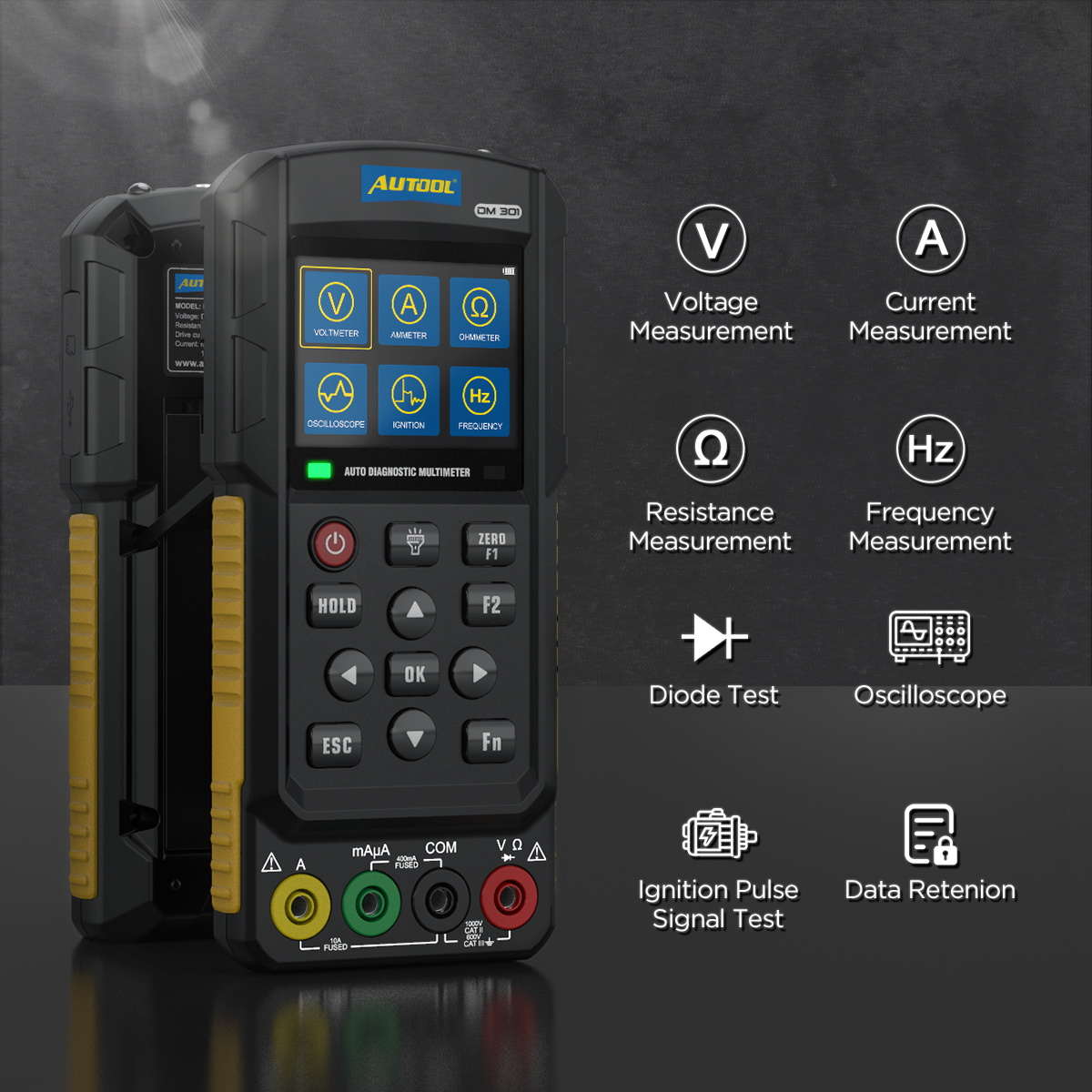
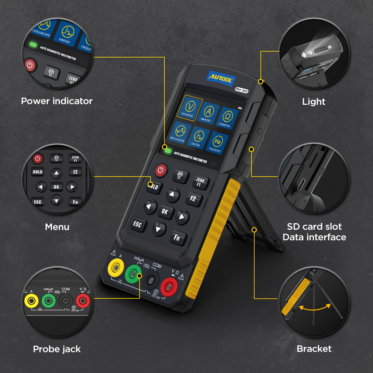
This guide treats the code list as a map. A scan tool supplies the addresses; a wiring diagram shows the streets; and an automotive meter checks the shared reference, low-reference, and signal paths at safe test points. The AUTOOL DM301 automotive multimeter and basic oscilloscope is one compact way to cover ordinary voltage, resistance, frequency, and simple waveform questions once the diagram identifies what is safe to measure. It does not replace correct back-probing, circuit limits, or a multi-channel scope when several signals must be timed together.
The objective is a bounded conclusion: prove whether the shared supply is healthy, pulled low, open, shorted, or only one part of the problem. Do not inject power into a reference, signal, data, SRS, or unknown module circuit. Preserve the evidence before disconnecting anything.
Quick answer: Treat the code cluster as a circuit map. Preserve scan data, identify the exact shared reference and low-reference paths, measure safely with the circuit assembled, isolate one branch at a time, and verify every sensor after the shared supply returns.

In this guide
Read the code cluster as a map
Start with the exact DTC numbers, modules that set them, status flags, freeze-frame data, and the conditions under which the complaint appears. “Low input” on three circuits is a different neighborhood from one “high input,” one rationality code, and one communication code. Record whether the codes are current, pending, history, or network consequences. Also save the live values before clearing anything. A fixed minimum, fixed maximum, or synchronized dropout can be more revealing than the wording of the code.
Group the complaints by time. Did all values become implausible at key-on? Does the engine start normally until vibration, heat, or an accessory load appears? Did recent work disturb a harness, ground, intake component, battery, or connector? A shared-circuit diagnosis becomes stronger when several symptoms begin together, but coincidence remains possible. The map is a hypothesis, not a verdict.
| Evidence | What it may suggest | What it does not prove |
|---|---|---|
| Several low-input codes | Shared reference or low-reference disturbance | A failed controller |
| One value recovers when another sensor is unplugged | A branch may be loading the shared circuit | That the unplugged sensor itself is bad |
| Reference is correct at one sensor | Supply reaches that test point now | Every splice and branch is healthy |
| Stable DC reading | Average voltage is present | No intermittent glitch exists |
Build the shared-circuit neighborhood
Use vehicle-specific wiring information to list every component on the named reference and low-reference circuits. Follow splice numbers, connector cavities, harness junctions, and controller pins rather than assuming every “5 V” label is the same supply. Many controllers divide sensors among multiple regulated feeds. Components that look related mechanically may live on separate electrical streets; components on opposite sides of the engine may share one splice.
Draw a small working map: controller source, main splice, each branch, each return, and accessible test points. Add recently serviced areas and places where the loom bends, rubs, traps water, or passes close to heat. Mark any component that can internally short a reference to ground or another circuit. This diagram makes the next step deliberate: you will know which measurement changes the hypothesis and which connector can be reached without damaging terminals.
Do not forget low reference. A healthy regulated supply with a weak sensor ground can shift several signals together. Compare the diagram’s dedicated low-reference paths with chassis grounds; they are not automatically interchangeable. Testing against the wrong ground can make a bad return look good.
Protect the evidence before unplugging
Before touching a connector, capture the symptom with the circuit assembled. Key position, engine state, battery voltage, temperature, vibration, and loads all matter. Photograph connector locks and harness routing if access requires disassembly. If the fault is intermittent, gently move only the suspect section while watching the chosen live value or meter; violent “wiggle testing” can create a new open and erase the original clue.
Use high-impedance, correctly rated equipment and approved back-probing methods. Never spread a terminal with an oversized probe. Piercing insulation can invite corrosion and should be avoided unless the service method allows it and the repair is sealed properly. Resistance checks belong on de-energized circuits with modules protected as the procedure directs. A resistance value on an energized network is not useful evidence and can damage equipment.
Check the reference at a safe test point
Choose an accessible sensor on the suspected shared feed and identify reference, return, and signal from the connector view. With the circuit assembled where possible, compare reference-to-low-reference and reference-to-a known ground. Then compare low-reference to battery negative under the operating condition. These measurements separate a missing supply from a lifted return without inventing a universal voltage-drop limit.
Nominal “5 V” is a circuit name, not permission to accept one exact number on every vehicle. Use service information for tolerance and test conditions. A reading near zero can result from a shorted branch, open source, controller protection, wrong pin, or bad test connection. Battery-level voltage on a reference is a stop sign: recheck identification and investigate a cross-short before connecting more components.
If a basic scope is appropriate, use it to look for dropouts that a digital display averages away. Set the time base to the event you can reproduce—key movement, harness movement, throttle travel, or heat—and save a known-good interval beside the fault. One channel can reveal a dropout. It cannot establish the timing relationship among several channels as efficiently as a multi-channel automotive scope.
Use disconnect tests without parts darts
Disconnecting branches can be informative when the diagram, key state, and connector procedure allow it. Unplug one component, observe whether the shared reference and other sensor values recover, record the result, reconnect, and move to the next branch. Change only one condition at a time. Randomly unplugging several sensors destroys the ability to attribute a recovery and may add expected codes that obscure the original group.
Recovery after unplugging a component narrows the fault to that component or its branch. Inspect the branch for chafing, water, terminal tension, and cross-contact before buying the sensor. If unplugging a harness junction restores the supply, the short may be anywhere downstream. If every branch is isolated and the reference remains absent, verify the controller pin, power, grounds, and the exact enabling conditions before suspecting the controller.
| Disconnect result | Next question |
|---|---|
| Reference returns and stays stable | Is the component internally loading it, or is its branch shorted? |
| Reference changes only while harness moves | Where is strain, abrasion, or terminal movement concentrated? |
| No branch changes the reading | Is the source enabled, is the test point correct, and are controller powers/grounds sound? |
| One signal remains wrong after reference recovery | Does that sensor have a separate signal, return, mechanical, or calibration fault? |
Separate supply, ground, signal, and module faults
Think in four columns. Supply evidence asks whether the regulated feed reaches the load. Ground evidence asks whether the return stays close to its intended reference while current flows. Signal evidence asks whether the output changes plausibly with the measured condition. Module evidence begins only after its powers, grounds, connector terminals, circuit loads, and required inputs have been checked.
A scan value alone crosses several layers: physical quantity, sensor element, wiring, controller conversion, network transport, and scan-tool display. Compare it with an independent observation where practical. A pressure sensor that reports an impossible value may be responding to real mechanical pressure, a blocked port, a bad return, or a corrupted signal. Restoring a shared feed can clear the cluster while leaving one genuine sensor fault behind.
This is why “the 5 V came back” is an intermediate finding. Reconnect branches one at a time, watch the supply, and confirm each signal through its expected operating range according to service data. A neighborhood is repaired only when its streets remain open with all residents connected.
Compare the tool routes
The market is better understood as methods than as a sales ranking; no auditable public model-level share dataset was found for this niche. A conventional professional multimeter such as the Fluke 88V emphasizes rugged passive measurement. PicoScope 4425A and TiePie automotive scopes add multi-channel capture and deeper waveform work. Autel’s MaxiScope route links scope work to a scan ecosystem. Hantek provides value-oriented scopes, while the MRCARTOOL B550 combines passive tests with powered-probe functions that demand tighter circuit judgment.
| Route | Best fit | Main tradeoff |
|---|---|---|
| Quality multimeter | Reference, return, continuity, and voltage-drop checks | May miss fast intermittent events |
| Compact meter/basic scope | One-tool field triage and simple waveform confirmation | Limited channels and advanced analysis |
| Multi-channel automotive scope | Correlation, glitch capture, current ramps, guided tests | Higher learning and equipment band |
| Scan tool plus diagram | Code context, live data, topology, active tests | Does not directly prove circuit integrity |
| Outsource/no-buy | Rare advanced network or scope cases | Less control over turnaround |
Choose the instrument by the electrical question. A passive automotive meter is usually enough to prove whether a shared reference reaches a connector, whether the low-reference path has unwanted drop, or whether a safely isolated conductor is open. When a changing signal or brief dropout remains possible, a combined meter and basic waveform display such as the DM301 can extend that same workflow without turning the test into component activation.
A Fluke-style professional meter is the stronger route when passive measurement, service, and measurement pedigree dominate. A Pico, TiePie, or other automotive scope is the better answer when multiple signals must be synchronized or recorded deeply. Powered circuit tools belong only on positively identified conventional circuits; they are not a shortcut for references, networks, module pins, or SRS. The complete method is the one that answers the mapped circuit question safely.
Stop before a risky circuit test
Stop if pin identity is uncertain, the diagram does not match the vehicle revision, a terminal is damaged, or unexpected battery voltage appears on a reference circuit. Stop before applying power to any reference, signal, controller output, network line, SRS circuit, or unknown pin. Also pause if the fault involves high voltage, a safety system, immobilizer consequences, or access that can cause the engine to start unexpectedly.
Do not condemn a controller because its output is low while a downstream short remains connected. Do not substitute a test light for a high-impedance meter on a module-managed reference unless the OEM procedure explicitly calls for that load. And do not use generic internet pinouts as a connector view. These are not cautious formalities; they keep a recoverable circuit fault from becoming a damaged module or deployed restraint.
A five-minute neighborhood worksheet
Before the first measurement, write four rows on the job card: affected sensor/circuit, shared reference name, shared low-reference name, and the first safe test point. Add columns for key-on value, fault-state value, and result after isolating one branch. This prevents values from different grounds or operating states being compared as though they were equivalent.
If no common feed or return appears on the exact diagram, retire the shared-reference hypothesis instead of forcing the codes into it. Look for a common connector, power/ground event, network loss, or mechanical condition. A useful map also tells you when the neighborhood theory is wrong.
Verify the neighborhood after repair
Verification should recreate the original conditions, not merely clear the dashboard. Reassemble every connector, secure the harness in its original clips, and load the vehicle electrically as it was when the fault appeared. Confirm the reference at the chosen point, compare all affected live values, scan every relevant module, and perform the service-information drive or operating check if it is safe and required.
Document what failed and what proved the repair: for example, a chafed shared branch pulled the regulated feed low; isolating that branch restored the supply; repairing and securing the wire kept the supply and all signals stable during the same heat-and-vibration condition. That statement is stronger than “replaced sensor, code gone.” It preserves the neighborhood map for the next technician and makes a comeback easier to distinguish from a new fault.
Questions that test the neighborhood theory
Can I unplug sensors until the engine starts? Only when the wiring diagram and service procedure make each disconnection safe, and only one branch at a time. An engine that starts after a branch is isolated tells you the shared feed may have recovered; it does not distinguish the component from its wiring or prove the remaining sensors are accurate.
Does exactly 5.00 V mean the circuit is good? No. It is one reading at one point and moment. Check the specified tolerance, low reference, response under the fault condition, and stability with every branch connected. A fast dropout may be absent from the displayed average.
When is a controller reasonable to suspect? After exact circuit identification; downstream loads isolated as allowed; controller powers, grounds, terminals, and enabling states verified; and output still fails the manufacturer’s test. Even then, confirm programming, replacement, and immobilizer consequences before ordering.









Comments 0
Questions, fixes, and real-world diagnostic notes from readers.
Be the first to share a diagnostic result or ask a follow-up question.