
OBD2 Scanner Will Not Communicate? Prove DLC Power, Ground, and Network First

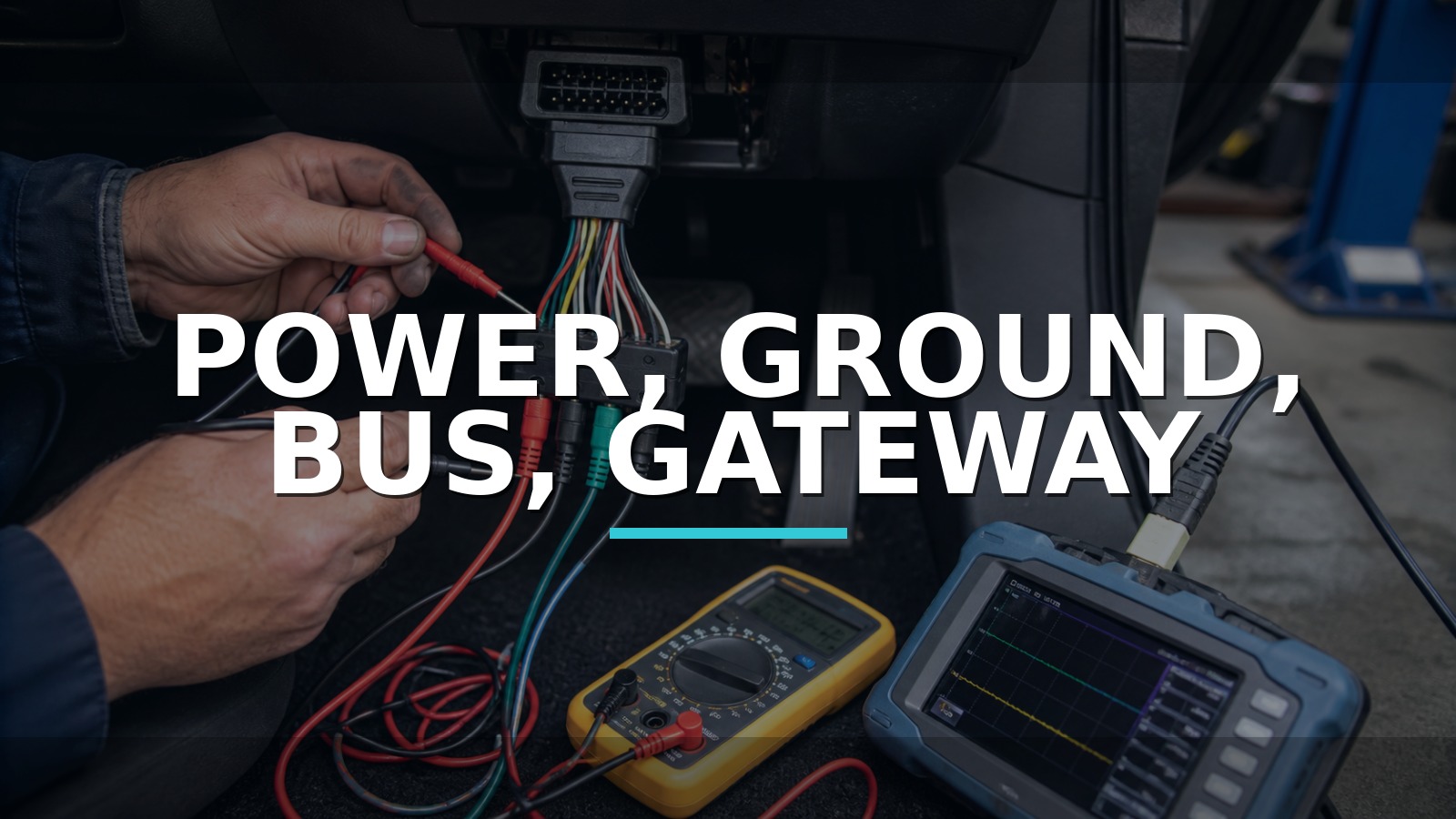
Power, Ground, Bus, Gateway
Communication requires four agreements: the diagnostic connector must be physically sound, the scan tool must receive suitable power/ground, an expected protocol path must exist, and the requested module must be awake and reachable through any gateway. “No communication” does not tell you which checkpoint refused entry.
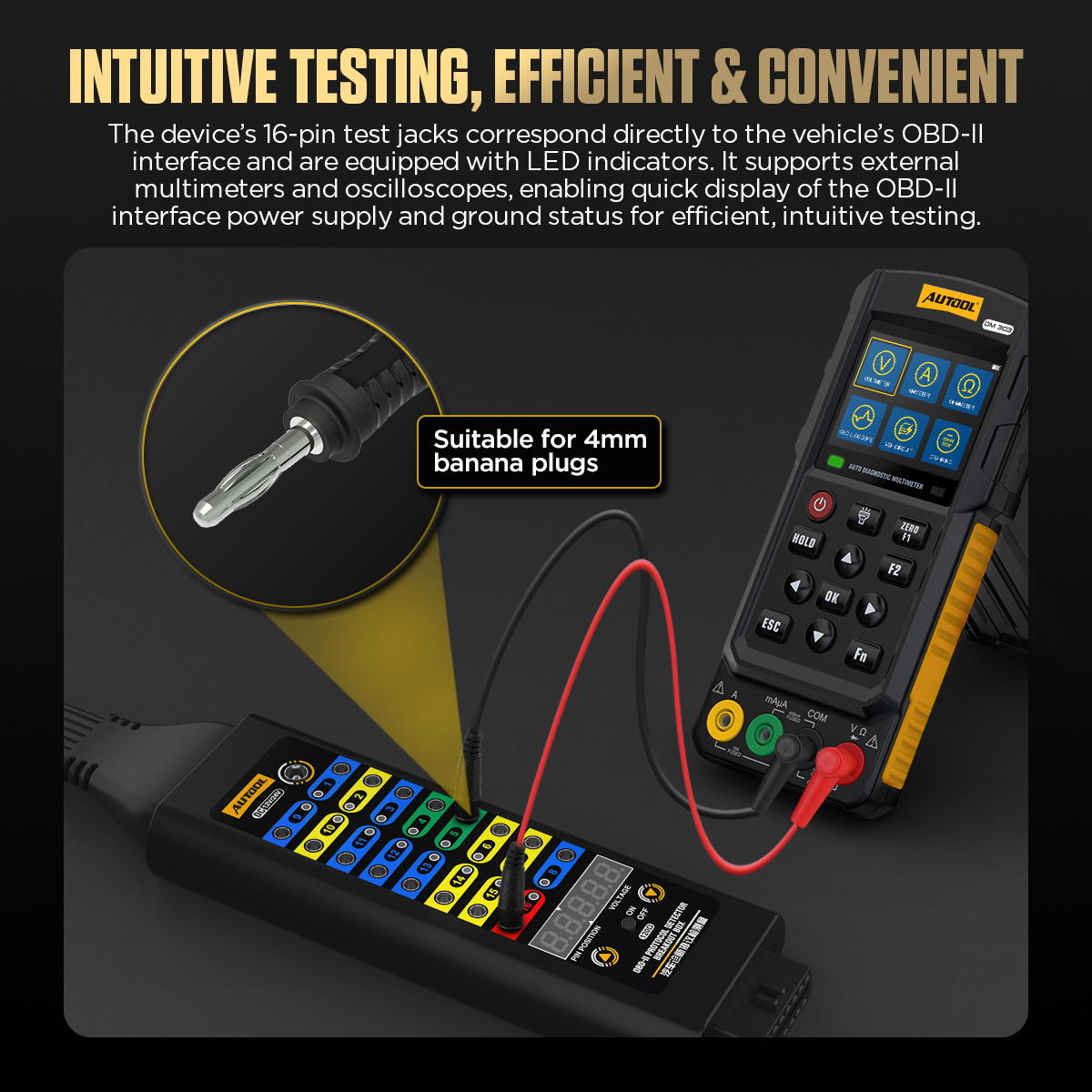
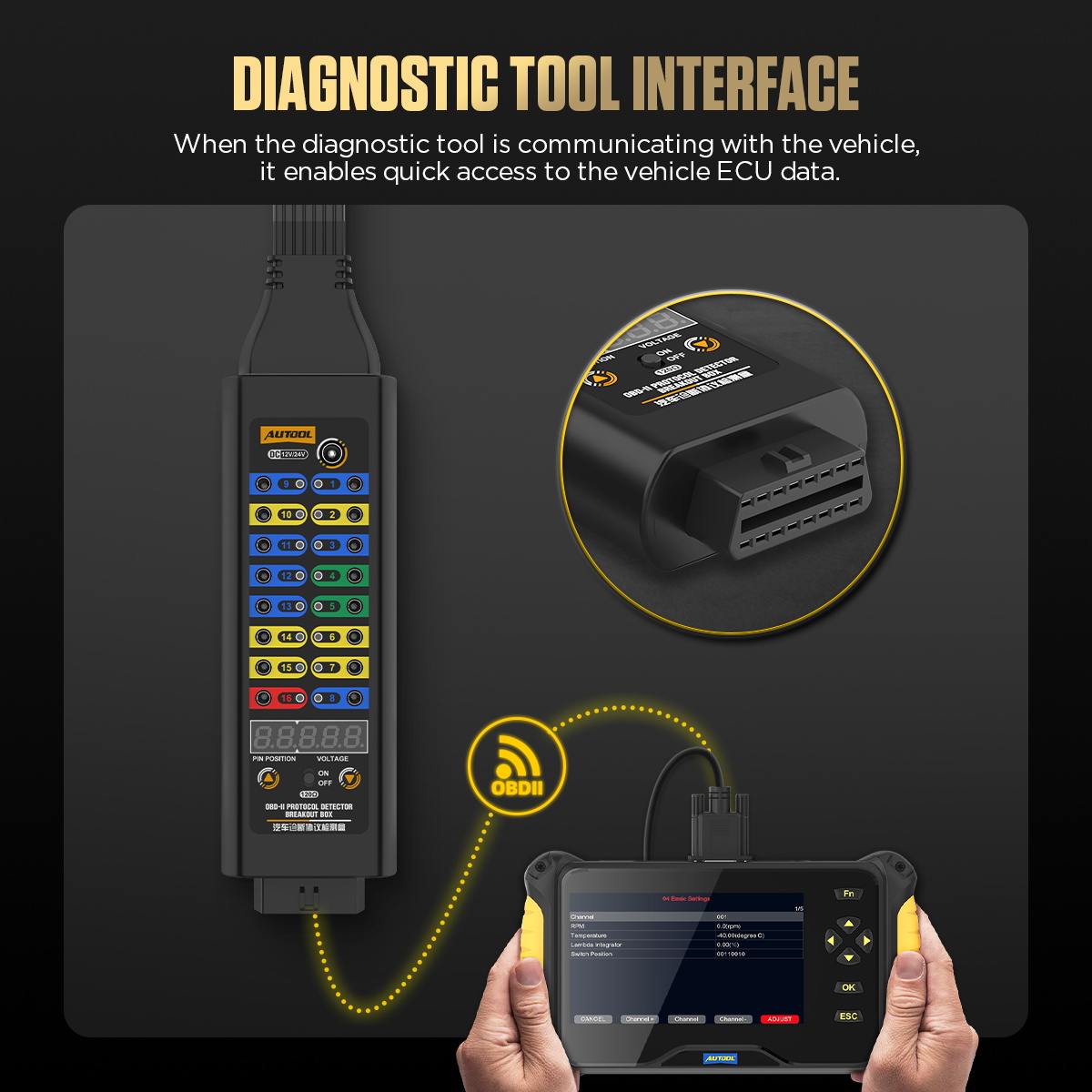
To test connector power, grounds, and identified communication pins without repeatedly back-probing the DLC, use a passive pass-through breakout box that keeps the scan tool connected while exposing protected test points. The AUTOOL OBD2 Breakout Box Premium Version is one example with identified 4 mm access points for observing the circuits named by the diagram. It makes access easier; it does not identify every protocol, bypass a security gateway, add software coverage, or tell an asleep module to wake.
Move through the gates in order and preserve evidence. Never short, power, or load an unknown DLC pin. Resistance and waveform tests require the correct network, vehicle state, diagram, and procedure.
Quick answer: Define whether communication loss is total or selective, inspect the exact connector, prove DLC power and grounds under an allowed load, identify the expected protocol/gateway path, and use resistance or waveform tests only in the correct network state.
In this guide
- Gate one: reproduce and scope the silence
- Gate two: inspect the connector
- Gate three: prove power and ground
- Gate four: identify the expected protocol path
- Separate total silence from one-module silence
- Protect the network while testing
- Use resistance or waveform tests only when applicable
- Compare breakout and scope routes
Gate one: reproduce and scope the silence
First decide whether the failure is total or selective. Does the scan tool power up? Can it identify the vehicle? Does generic OBD fail while manufacturer diagnostics works, or vice versa? Can one module communicate while another is absent? Does a second known-compatible tool behave the same? Record key position, battery voltage, recent battery or module work, aftermarket accessories, warning lamps, and every successful/failed module.
Confirm the scan-tool software, cable, VCI, account/security status, and exact vehicle coverage on a known-good vehicle where practical. A tool that fails everywhere is not evidence against the car. A generic reader may access emissions data but not body/ABS modules. A gateway may require authorization. Define the silence before opening the connector.
| Symptom | First branch | What it does not prove |
|---|---|---|
| Tool has no power | DLC supply/ground, cable, tool | Network is down |
| Generic OBD works, one module absent | Coverage, gateway, module branch | DLC pins are all healthy |
| No tool communicates with this vehicle | Shared vehicle-side path likely | Controller is failed |
| Intermittent connection with connector movement | Terminal/cable fit deserves inspection | Network itself is healthy |
Gate two: inspect the connector
Use the vehicle’s connector view, not an unlabeled internet diagram. Inspect DLC mounting, shell damage, bent/recessed/spread terminals, foreign objects, corrosion, aftermarket taps, and signs that a previous probe enlarged a cavity. Confirm the connector is the expected diagnostic port; adapters or market-specific connectors may be involved on older or specialty vehicles.
Do not force the scan plug or a breakout box into damaged terminals. Added pass-through connectors can change terminal pressure, so compare behavior with and without the accessory only when safe. Photograph the original state before moving an aftermarket tracker, insurance dongle, radio harness, alarm, remote starter, or fleet device. These devices may load power or communications, but disconnecting them can affect learned settings or security; follow the applicable procedure.
Gate three: prove power and ground
Use exact service information to identify battery feed, switched feed if present, signal grounds, chassis grounds, and protected circuits. Check the relevant fuse electrically and inspect its terminals. Measure supply at the DLC relative to the intended ground, then prove the ground path under an allowed load. A high-impedance meter can display voltage through resistance that cannot reliably power the VCI.
Compare DLC supply during connection attempts and key transitions. If it collapses, divide the feed through fuse, junction, and connector. Measure ground voltage drop with an appropriate load instead of assuming continuity means current capacity. Do not apply a heavy test lamp to a module-managed supply or signal ground unless the OEM method says it is safe.
Gate four: identify the expected protocol path
OBD-II uses a standardized connector but has supported multiple physical protocols across years and markets. Modern vehicles may place a CAN path at common pins, route diagnostics through a central gateway, or use additional manufacturer-specific networks. Older vehicles can use K-line or other paths. The exact diagram tells you what should be present on this application.
Observe which pins are populated and compare them with the connector view—never infer function from pin location alone. Use scan-tool topology and network codes from communicating modules to identify a missing branch. A gateway that is alive on one side but not another changes the test plan. If security authentication is required, physical bus activity cannot substitute for authorized access.
Separate total silence from one-module silence
Total silence across known-good tools prioritizes DLC power/ground, common network path, gateway, and major vehicle state. One missing module prioritizes that module’s powers, grounds, wake line, branch wiring, termination, and coverage. Several related modules absent may share a network segment, splice, fuse, or gateway channel.
Scan every reachable module before clearing codes. “Lost communication with…” codes in other modules can reveal which controller disappeared and when. A module may be intentionally asleep or absent from a trim level, so use the vehicle configuration. Low battery voltage can create a forest of network faults; stabilize the vehicle before drawing topology conclusions.
| Scope of silence | Strong evidence next | Common mistake |
|---|---|---|
| Tool unpowered | Loaded DLC feed and ground checks | Testing CAN first |
| All modules silent, tool powered | Expected protocol/gateway activity | Condemning ECM immediately |
| One network segment absent | Diagram, gateway side, termination, branch isolation | Shorting pins to “wake” it |
| One module absent | Module power/ground/wake and coverage | Treating generic OBD as full coverage |
Protect the network while testing
Keep battery voltage stable using an approved method, but do not attach an unverified charger during sensitive diagnosis/programming. Turn ignition and loads on/off only as the procedure directs. Disconnecting modules can alter termination and create new codes; record each change and reconnect before moving on. Never use a powered probe on communication lines.
Use high-impedance probes and short, secure connections. Ground a scope as the equipment and vehicle architecture require. On high-voltage or isolated systems, ordinary ground-referenced instruments can be hazardous. Stop if the network type, pin identity, voltage domain, or isolation requirement is uncertain.
Use resistance or waveform tests only when applicable
A familiar CAN resistance value is not universal permission to measure. The network must be powered down in the specified state, capacitors settled, and the correct terminated segment identified. Gateways, switched termination, multiple CAN buses, Ethernet, LIN, FlexRay, and manufacturer architectures change what a resistance check means. Measure only when the OEM test calls for it.
A scope can show bus activity, dominant/recessive levels, noise, reflections, or a stuck line. Compare both relevant lines and the same physical point to known-good/OEM examples. Activity proves messages are moving, not that the requested module accepts or responds correctly. Decoding and multi-channel correlation may require a dedicated automotive scope beyond a simple breakout box.
Compare breakout and scope routes
There is no defensible public model-level sales ranking for DLC breakout boxes. Pico Technology’s CAN Test Box emphasizes scope integration; AESwave and OTC offer professional breakout/network accessories; Autel and Launch integrate topology and network tests into scan ecosystems; basic pin boxes provide inexpensive access; a custom OEM harness may be required for protected or nonstandard connectors.
| Route | Best use | Boundary |
|---|---|---|
| Passive pass-through breakout | Safe, repeatable pin access while scanning | Needs diagram and separate meter/scope |
| LED protocol/activity box | Quick presence indication | LEDs cannot characterize waveform quality |
| Scope-focused CAN box | Multi-channel physical-layer work | Higher equipment/skill band |
| Scan-tool topology | Logical reachability and module relationships | Depends on coverage and working access |
| Outsource/no-buy | Security, Ethernet, complex gateways | Less in-house control |
If the missing evidence is voltage or waveform access at identified DLC pins while the scanner remains online, a passive pass-through breakout box is the relevant tool type. The AUTOOL premium box provides 4 mm test points for that job, which can make repeated power, ground, and supported-bus observations more controlled than improvised back-probing. Pair it with a suitable meter or scope and the exact connector diagram; never infer pin purpose from a generic label alone.
A basic passive box may be sufficient for rare power-and-ground checks. Professional Pico or AESwave-style accessories make more sense when durable lab leads, training, and multi-channel correlation are recurring requirements. OEM tooling remains necessary when secure gateways, Ethernet diagnostics, wake-up strategy, or manufacturer procedures control access. A breakout box exposes a path; it does not create communication that the vehicle or scan tool cannot support.
Create a four-gate pass sheet
Give every checkpoint a simple outcome: connector condition, loaded supply, loaded grounds, and expected protocol/gateway reachability. Attach measurement locations and vehicle state. “Pass” should mean the defined test passed, not that the part looked good. If gate three fails, do not continue interpreting random waveform activity at gate four.
This pass sheet also prevents the breakout box from becoming a dashboard. LEDs or visible activity can be helpful orientation, but they do not replace voltage, voltage drop, differential waveform, message decoding, or topology evidence. Use the access points to answer a written question and disconnect them when that question is closed.
Account for wake-up and sleep
Network state can change as doors open, keys move, chargers connect, and scan tools request sessions. Record the time since key-off and which event woke the vehicle. A module that disappears after sleep may have an intended power mode, a wake-line fault, or a parasitic network issue. Repeatedly opening doors can keep the bus active and hide the complaint.
For intermittent cases, a scope or logger may capture physical activity while the scan tool loses logical access. Keep the monitoring connection passive and battery support appropriate. Do not leave an improvised breakout arrangement where it can short during an unattended overnight test.
Know when standardized OBD ends
The 16-pin connector standardizes physical access more than it standardizes every diagnostic function. Emissions-related generic data, manufacturer module access, secure gateways, pass-thru programming, and newer Ethernet paths involve different standards and permissions. A successful generic emissions session does not certify full vehicle communication, and a failed body-module session does not mean generic OBD is broken.
Reconnect and rescan without erasing evidence
Restore every module, fuse, aftermarket connection, terminal lock, and trim piece. Remove breakout/test equipment and confirm the scan tool connects directly. Repeat the original key transition and communication attempt with stable battery voltage. Run a complete topology or module scan, compare the before/after list, and save remaining codes before deciding which are test-created history.
The closure record should identify the failed gate: a recessed power terminal, high-resistance ground, shorted network branch, sleeping module from lost feed, gateway authorization, or scan-tool coverage. If the repair merely made one tool work while another still fails, explain why. “Communication restored” is credible only when the original path, requested modules, and conditions are all verified.
Checkpoint disputes
The breakout activity lights flash—does that prove CAN is healthy? No. They may show voltage transitions on selected pins. They do not prove correct differential levels, termination, timing, messages, gateway routing, or response from the requested module. Use a scope/decoder and topology evidence when those questions matter.
Can I jump power into pin 16 to wake the tool? Not as a shortcut. First identify and repair the protected vehicle feed. External power can backfeed modules or bypass protection, and connector conventions do not authorize improvised injection.
Why does a cheap reader connect when a professional tool will not? They may choose different protocols, cables, software paths, gateway sessions, or power behavior. Test the professional tool on a known-good application, verify updates and exact coverage, and compare which diagnostic layer each attempted.
The non-communication triage card
- Test tool/cable/software on a known-good compatible vehicle where possible.
- Record which functions and modules connect or fail; save all reachable network codes.
- Inspect the DLC and exact connector view before inserting breakout or probes.
- Prove supply and intended grounds under an allowed load.
- Identify the expected physical protocol and gateway path for this application.
- Move from total silence to segment/module tests; change one connection at a time.
- Use resistance or scope only in the correct network and power state.
If the problem began after accessory installation, record and isolate that branch by its procedure—but remember that disconnecting a telematics or security device may itself change network state. If the problem is limited to secure functions, verify authentication before touching wiring. These two checks prevent hours of physical-layer diagnosis for a software session that was never permitted.
Decision rule: Do not cross a checkpoint until the previous one has a recorded pass. A healthy connector with loaded power/ground and the expected physical path can justify gateway, module, or software investigation; anything less keeps the case at the DLC. Breakout access is valuable because it makes that order easy to observe, not because it makes every pin safe to manipulate.
Keep a known-good DLC extension or breakout reference only if its own terminal condition is checked regularly. Diagnostic accessories wear too; an intermittent pass-through lead can imitate the vehicle fault and make every checkpoint result unstable.









Comments 0
Questions, fixes, and real-world diagnostic notes from readers.
Be the first to share a diagnostic result or ask a follow-up question.