
How to Use the MRCARTOOL V310 Six-Cylinder Fuel Injector Tester

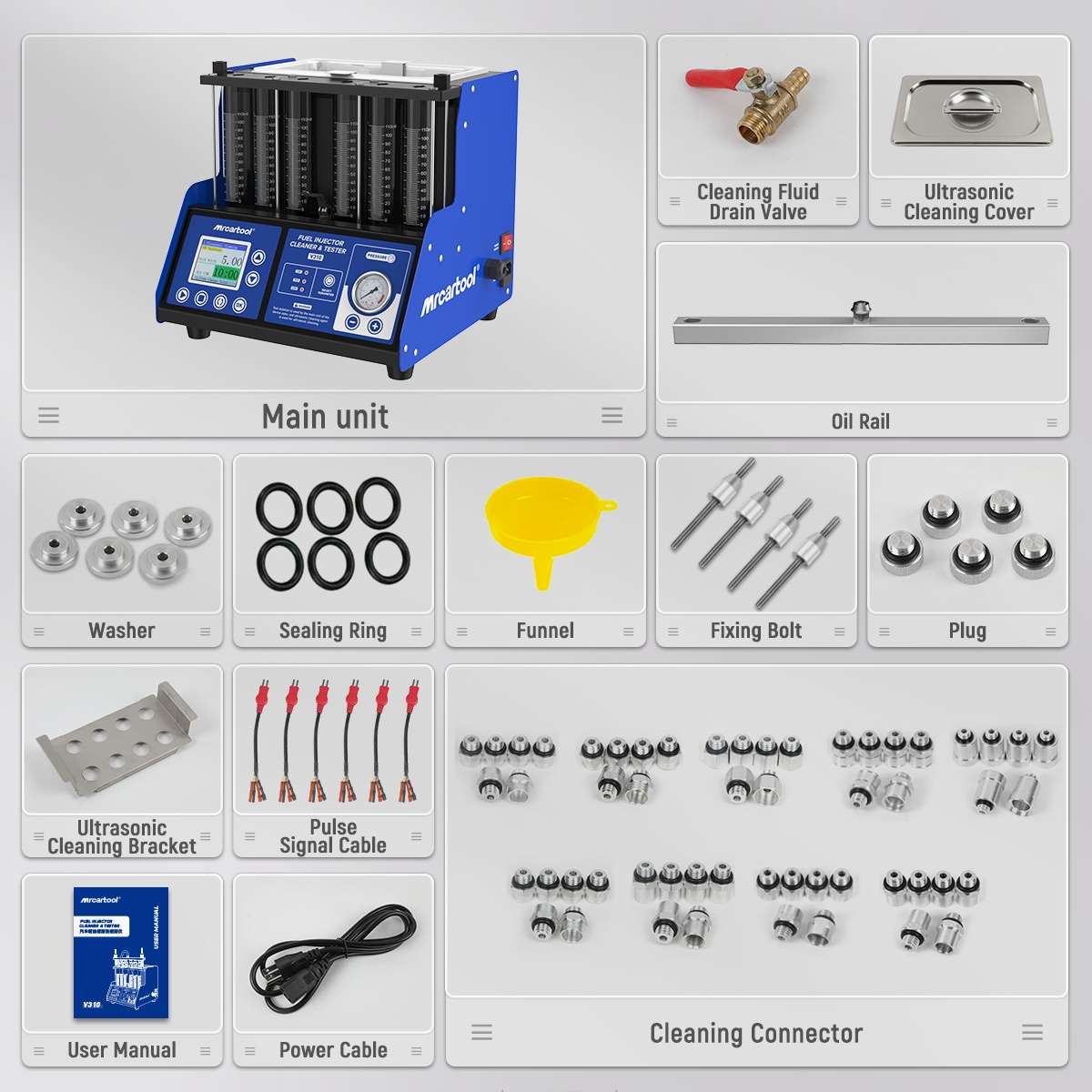
The MRCARTOOL V310 six-cylinder fuel injector tester combines a 2,000 ml ultrasonic tank, six 110 ml measuring cylinders, selectable injector drive and a 3.2-inch TFT workflow. Its six channels can reveal a weak injector within a set, but only when every injector is identified, cleaned, mounted, energized, pressurized and measured under the same conditions.
Quick answer: Verify the delivered nameplate and injector’s required drive before power. Keep dedicated ultrasonic cleaning agent and separate test agent in their own circuits. Never run the tank dry or immerse pulse connectors. Mount adapters and O-rings squarely, secure both locking rods, connect six mapped leads and the supply hose, select the verified 12 V, 70 V or 120 V output, then use injector-specific pressure—not a storefront range—to prove sealing and compare pattern or volume.
In this guide
Know the V310 limits before connecting an injector
The manual lists AC 110/220 V ±10% supply variants, 40 kHz/70 W ultrasonic cleaning, 0–20 ms pulse width, 0–10 minute work time, 0–9,900 injection count, a 0–7,500 rpm simulation range and 0–0.6 MPa system pressure. The current panel also presents 12 V, 70 V and 120 V injector-drive selections. These are machine capabilities—not automatic settings for an unknown injector.
The product page separately mentions approximately 5–8 bar, but 0.6 MPa equals 6 bar and is the manual’s stated machine ceiling. Do not use 8 bar. The allowed test setting is the lower of the exact injector/service requirement and the delivered V310’s limit. If the injector pressure or drive voltage is unknown, do not test it.
- Use an uninterrupted protective ground and match the outlet/fuse to the delivered nameplate.
- Work in a dry, bright, ventilated, ignition-free area with splash eye protection and fluid-resistant gloves.
- Inspect the cord, TFT, pressure gauge, hose, rail, glass cylinders, tank, valves, leads, adapters and seals; stop for any damage.
- Map each injector by part number and source cylinder. Verify connector, adapter, 12/70/120 V drive, pressure and acceptance tolerance.
- Use dedicated compatible cleaning and test agents. Do not normalize the product page’s substitute suggestions over the manual’s prohibition of kerosene, gasoline and unapproved agents.
Stop: 12 V, 70 V and 120 V are different electrical drive outputs, not three intensity levels. A wrong selection can damage the injector or machine. GDI appearance alone does not choose the voltage.
Step 1: Remove, identify and inspect the injectors
Release vehicle fuel pressure and remove the injector set by the vehicle procedure. Preserve cylinder identity. Inspect each inlet, nozzle, housing, connector and O-ring. Replace cut, hard, flattened or swollen seals before a pressure test. Remove loose exterior contamination with approved cleaner and a soft cloth without pushing debris into an opening.
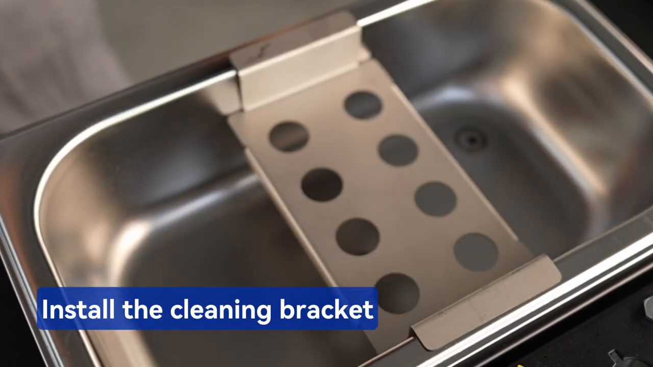
Step 2: Install the ultrasonic cleaning bracket
Place the supplied bracket flat in the stainless ultrasonic tank and support the compatible injectors in its holes. The official video shows the bracket seated before the injectors and leads are loaded. A stable bracket keeps nozzle sections at a common depth and keeps the bodies from striking the tank.
Step 3: Connect pulse leads and add cleaning agent
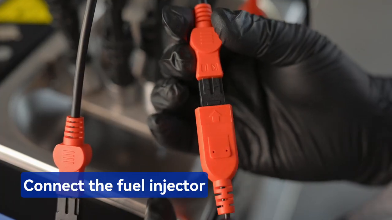
With output stopped, connect the correct pulse lead or adapter lead to every injector. Keep each cable connector above the liquid line. Add dedicated injector ultrasonic cleaning agent to the physical level required by the tank and fluid instructions; the video identifies the tank as 2,000 ml capacity, but capacity is not a direction to fill to the rim.
Turn on the grounded machine, select 01 Ultrasonic Cleaning on the TFT and set time; the manual gives 10 minutes as the default. Start the control program and enable the side ultrasonic switch. Use heating only when the approved agent and delivered instructions permit. Observe the full cycle and never energize a dry tank.
When cleaning ends, stop ultrasound and heat, remove the injectors carefully, let excess agent return to the tank and wipe their exteriors dry. Signal connectors must be dry before the six-channel test rail is assembled.
Step 4: Match rail adapters before filling the test circuit
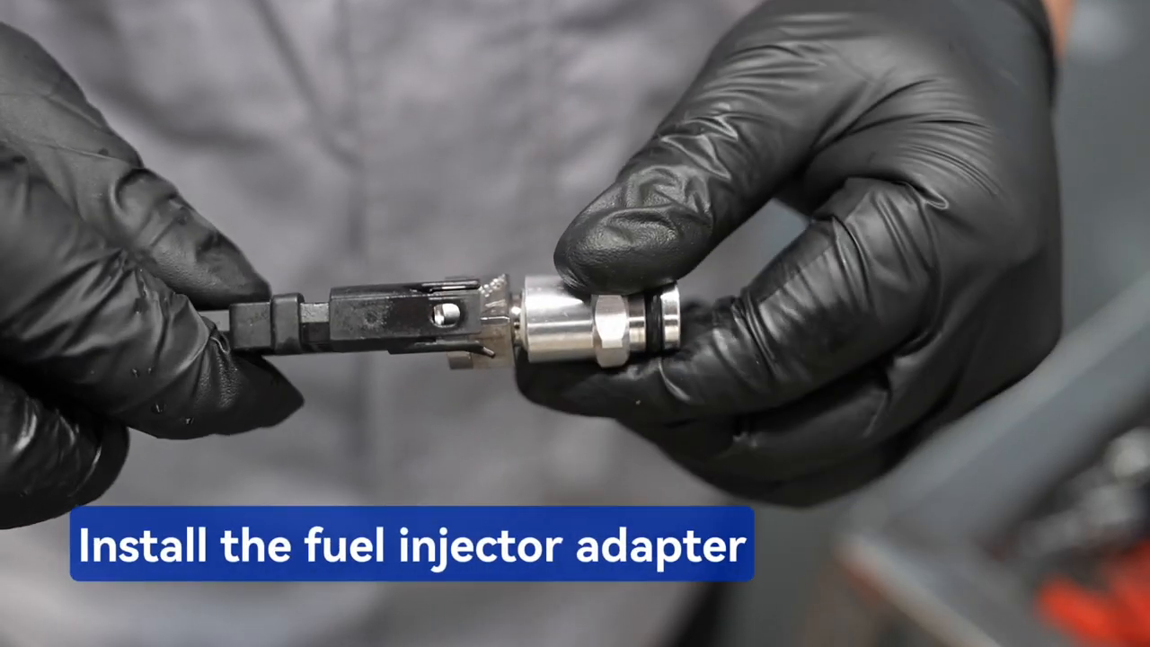
Choose the top-feed or other supplied connector that matches the exact injector inlet and intended flow direction. Lightly lubricate only a sound O-ring with a compatible lubricant and test-fit the injector straight. Similar diameter is not proof of a seal. Plug every unused path required by the delivered rail configuration.
Step 5: Add the separate test agent
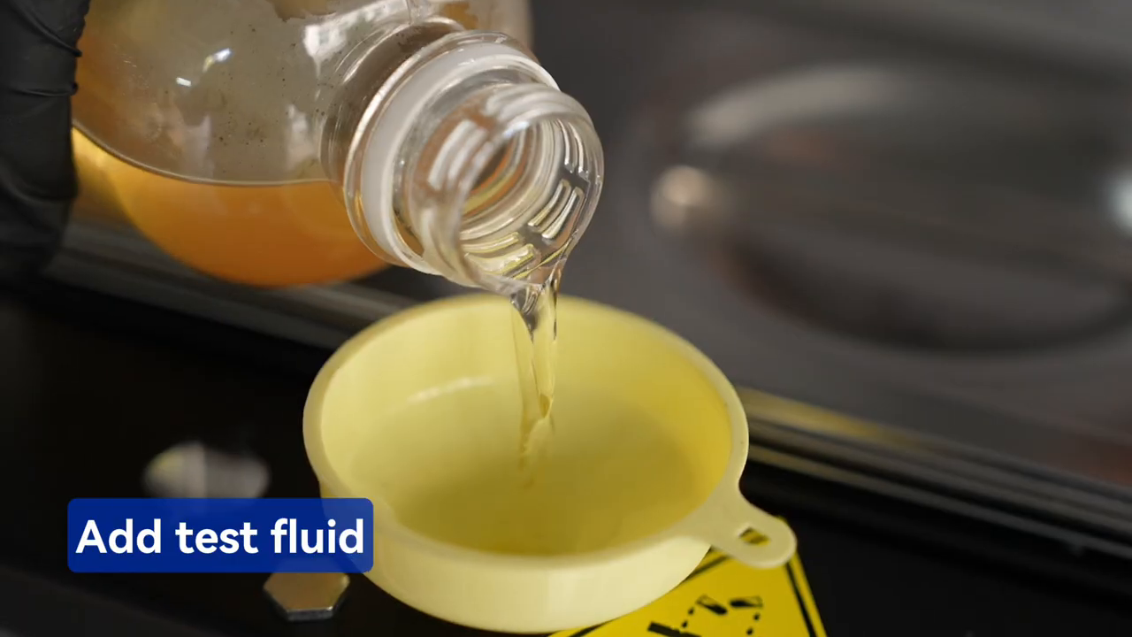
Place the drain controls in the preparation positions shown by the physical labels. Use the funnel to add approved injector test agent slowly through the V310 fill point while watching the side level window. The manual describes approximately 1,000 ml per fill. Stop at the marked operating level and inspect the cabinet and bench for leakage; do not fill until liquid reaches a measuring cylinder.
Step 6: Install, align and clamp up to six injectors
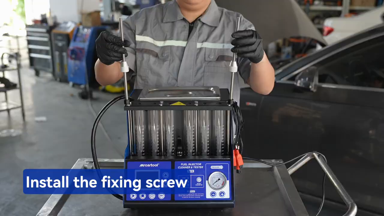
Install the chosen adapters in the oil rail, seat each injector straight and place the rail horizontally on the upper supports. Center every nozzle over its own cylinder. Install the two locking rods and tighten the lock nuts evenly. The rail must remain square and stable without hand support; the clamps are not tools for forcing a mismatched adapter to seal.
Step 7: Map signal leads and connect the oil-supply hose
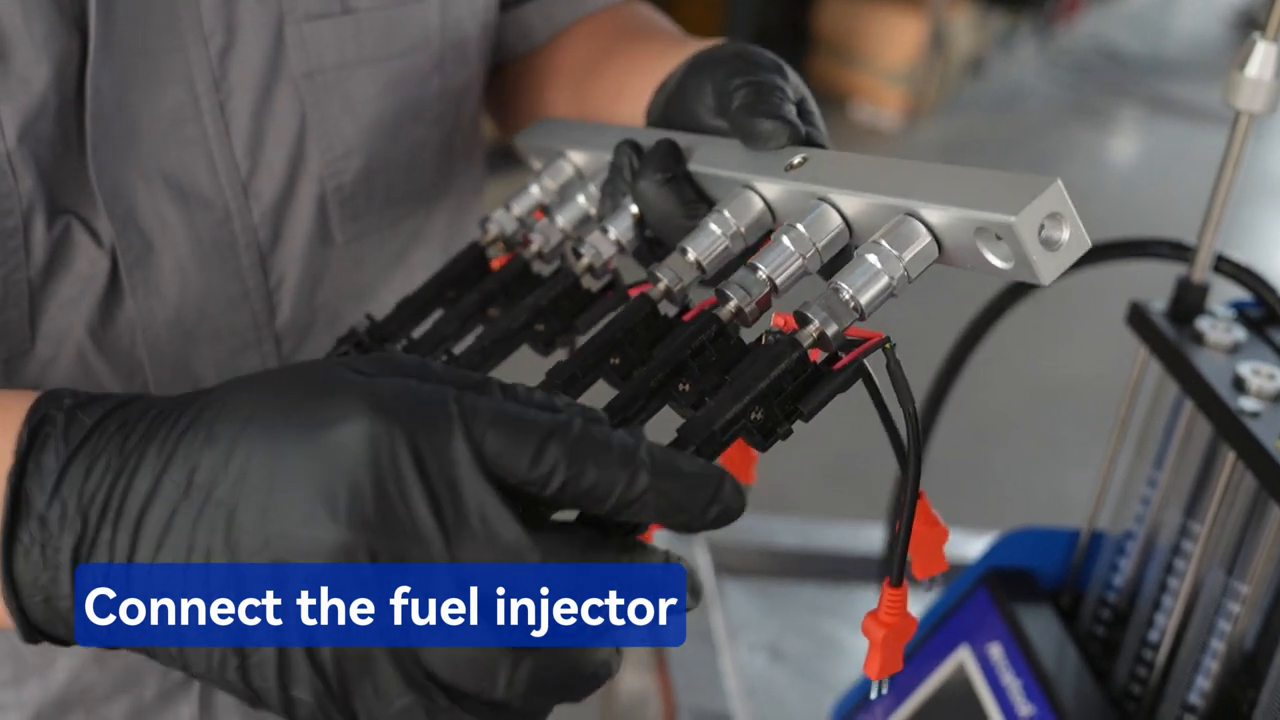
With the test function stopped, connect each dry signal lead to the injector above its corresponding cylinder. Route the leads so none can pull an injector sideways or contact wet surfaces. The video shows the complete six-injector harness attached only after the rail is clamped.
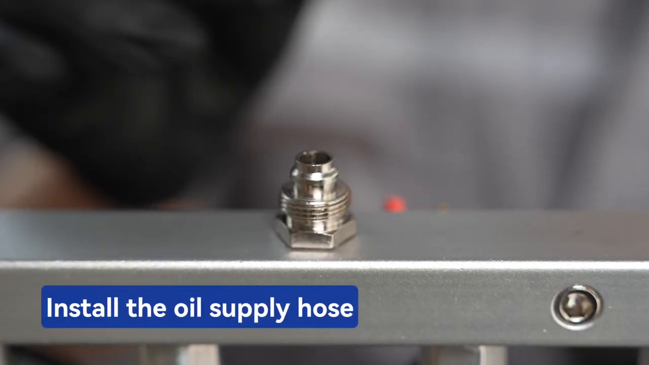
Attach the oil-supply hose to the rail fitting by hand and verify it starts square. Do not let the hose twist the rail. Recheck every O-ring, adapter, nozzle position, lock rod, lead and drain control before pressure is requested.
Do not start: Stop for an exposed O-ring, tilted injector, uneven rail, nozzle outside a cylinder, crooked hose, wet electrical connector, open unused path or unknown drain position.
Step 8: Set the TFT, injector voltage and pressure
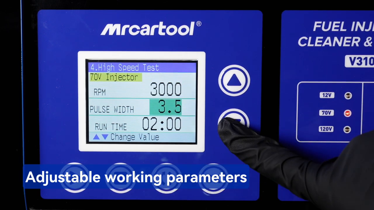
Use the TFT and function buttons to select the test item and edit the highlighted value. The screen shows function, injector drive, simulated rpm, pulse width and run time or count. Confirm 12 V, 70 V or 120 V from controlled injector data before Start. Set the exact pressure from the injector/service procedure and raise it gradually while watching the gauge and every joint.
| Function | Use | Control |
|---|---|---|
| 01 Ultrasonic Cleaning | Clean supported injectors in the separate tank | Agent, level, lead position, voltage and time |
| 02–04 Idle / Medium / High | Observe spray at fixed simulated conditions | Voltage, pressure, pulse width and time |
| 05 Acceleration | Run automatic 750–7,500 rpm simulation | Exact injector limits and secure assembly |
| 06 Variable Speed | Cycle 750, 4,500 and 7,500 rpm | Same set, voltage and pressure |
| 07 Leakage | Observe external setup and closed-nozzle sealing | Dry assembly, pressure and time |
| 08–10 Spray Volume | Collect idle, medium and high delivery | Equal baseline, count, pressure and reading method |
| 11 Reverse Flushing | Reverse-flow an approved injector with exact hardware | Injector approval, reverse adapters and guarded collection |
| 12 No-disassembly Cleaning | Use only with specified optional vehicle-service parts | No improvised vehicle connection; exact procedure required |
Step 9: Prove leakage control, then observe spray
Begin with Item 07 or the least-risk applicable procedure. Build pressure gradually. Wetness at the rail, hose or injector inlet is a setup fault; a droplet from a closed nozzle may indicate injector leakage. Stop, release pressure and inspect before deciding which one you are seeing. After the external setup remains dry, run an applicable fixed-speed function and watch all six patterns from outside the spray path.
Stop immediately for movement, rapidly falling pressure, abnormal pump noise, arcing, a hot connector or fluid outside the cylinders. A simulated rpm label is a bench-control condition, not proof that every in-engine electrical, thermal and hydraulic condition has been recreated.
Step 10: Compare six collected volumes
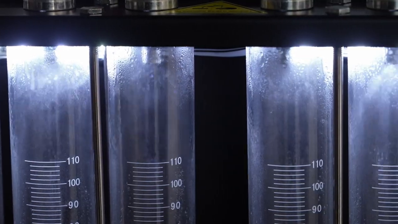
For Items 08–10, put all cylinders at the same readable baseline and move the drain handle only as the delivered collection procedure requires. Set the same injection count, collect all six channels together, stop before a cylinder becomes too full, let the liquid settle and read every meniscus at eye level. Record the values before returning reusable fluid to the reservoir.
The manual mentions a 2 percent within-set deviation, then defers to the injector technical manual. The exact service tolerance controls. If one channel is low, verify pressure, baseline, trapped air, adapter flow, rail alignment and lead mapping, then use a documented depressurized position/channel swap to see whether the difference follows the injector or the setup.
Step 11: Stop, depressurize and maintain
Press Stop, lower pressure and wait until the gauge and fluid behavior confirm no stored pressure. Turn off the ultrasonic/heater controls and main power, then unplug the V310 before loosening the hose, rail, lock rods or injectors. Treat every joint as pressurized until verified otherwise.
- Drain cleaning and test agents separately into compatible labeled containers; never mix them.
- Return test agent only when it remains approved and uncontaminated; dirty fluid can block cleaned injectors and damage the pump.
- Remove leads by their connector bodies and keep wet hardware away from the TFT and sockets.
- For long storage, drain the test reservoir as directed, perform the clean-fluid rinse described in the manual and protect all six glass cylinders from impact.
- Record injector identity, adapters, voltage, pressure, pulse width, count, readings and any controlled swap used to verify a difference.
Use the current MRCARTOOL manual download page whenever the nameplate, TFT menu, voltage options, rail, level window or delivered accessories differ from this sequence.
Troubleshooting
| What you see | Check next |
|---|---|
| No TFT display | Nameplate supply, grounded outlet, plug, switch and fuse; do not open the cabinet. |
| Injector does not pulse | Verified 12/70/120 V drive, correct lead, dry connector, function status and controlled channel swap. |
| Pressure is unstable | Physical fluid level, drains, supply hose, rail seals, unused paths and external leakage. |
| One cylinder reads low | Equal baseline, trapped air, adapter restriction, rail alignment, lead mapping and identical parameters. |
| Ultrasound does not start | Correct agent/level, Item 01 active, control Start and separate ultrasonic switch. |
| Fluid becomes dirty | Drain and replace it before contamination reaches cleaned injectors or pump components. |
Frequently asked questions
Can the V310 test every GDI injector?
No. Verify connector, adapter, drive voltage, pressure range and test method for the exact injector. The V310’s 12/70/120 V options and 0.6 MPa limit do not reproduce every direct-injection system.
Is 5–8 bar the V310 setting?
No. The manual lists a 0.6 MPa machine maximum, equivalent to 6 bar. Use the lower of the injector’s specified test pressure and the delivered machine limit; never use a storefront range to exceed either.
Can I mix cleaning agent and test agent?
No. They serve separate circuits and the manual prohibits mixing or replacing them with kerosene, gasoline and unapproved agents.
Can I test fewer than six injectors?
Only when the delivered rail can safely seal every unused path and support the installed injectors squarely. Use the supplied plugs/adapters and do not leave an open pressurized outlet.
Is one low cylinder enough to replace an injector?
No. Repeat the controlled setup and determine whether the result follows the injector or a channel, adapter or position. Combine repeatable bench evidence with the exact service tolerance and vehicle diagnosis.
Final V310 checklist
- Delivered nameplate, protective ground, TFT and machine limits confirmed
- Exact injector, adapter, connector, 12/70/120 V drive and pressure verified
- Cleaning agent and test agent kept separate; tank never run dry
- Pulse connectors remain above ultrasonic fluid
- Rail, seals, injectors, six leads and supply hose square, dry and secure
- External leakage passes before spray and volume collection
- Compared channels use the same voltage, pressure, pulse width and time/count
- Pressure released and power isolated before disassembly
- All six readings and any verification swap recorded
A six-channel bench is valuable because it exposes differences at one glance. Make that glance trustworthy: identify the hardware, clean with the right agent, map every injector, choose voltage and pressure from controlled data, prove sealing and collect every channel under the same conditions. The V310’s TFT makes settings easier to see; disciplined setup makes those settings meaningful.











Comments 0
Questions, fixes, and real-world diagnostic notes from readers.
Be the first to share a diagnostic result or ask a follow-up question.