
How to Use the AUTOOL TCA403/TCA404 Tire Changer

The AUTOOL TCA403/TCA404 is a professional tire changer. This guide combines the exact-product configuration with first-party tire-changer operating and wheel-protection guidance.
Quick answer: On a commissioned TCA403/TCA404, inspect the protectors and controls, identify the valve and TPMS, remove the valve core and verify zero pressure. Lubricate and break both beads, clamp the rim evenly, keep each bead in the drop center while demounting and mounting, then inflate from outside the tire trajectory within the lowest applicable tire, rim, machine and workplace limit. Finish with leak, pressure, balance and TPMS checks.
In this guide
Before you start
A tire changer combines a rotating table, clamping jaws, a powerful bead breaker and compressed air. The main avoidable risks are a pressurized tire at the bead breaker, hands in a pinch zone, a valve or TPMS sensor pulled by the bead, a rim marked by worn protection, and uncontrolled inflation. Use the machine only after exact-model commissioning and operator training, with the tire and wheel service information open.
- confirm the data plate and delivered control labels identify AUTOOL TCA403/TCA404, including whether the machine is the first or second variant in the combined model name;
- confirm the power and 8-10bar air supplies were installed and commissioned for this machine by qualified personnel;
- inspect jaw sleeves, mounting-head protection, bead-breaker pad, turntable, hoses, gauge, controls and guards before the wheel approaches;
- identify tire size, rim construction, direction markings, damage, prior repairs and the valve/TPMS position;
- prepare approved tire-mounting lubricant, eye protection, suitable hand protection, valve tools and the workplace inflation restraint; and
- verify the wheel and tire fit the stated machine range and the replacement tire is approved for the rim and vehicle.
Use the AUTOOL manual download center to locate the current instructions when a manual is available. The delivered model label and current vehicle service information control if an older image or remembered setting differs.
TCA403/TCA404 controls and specifications
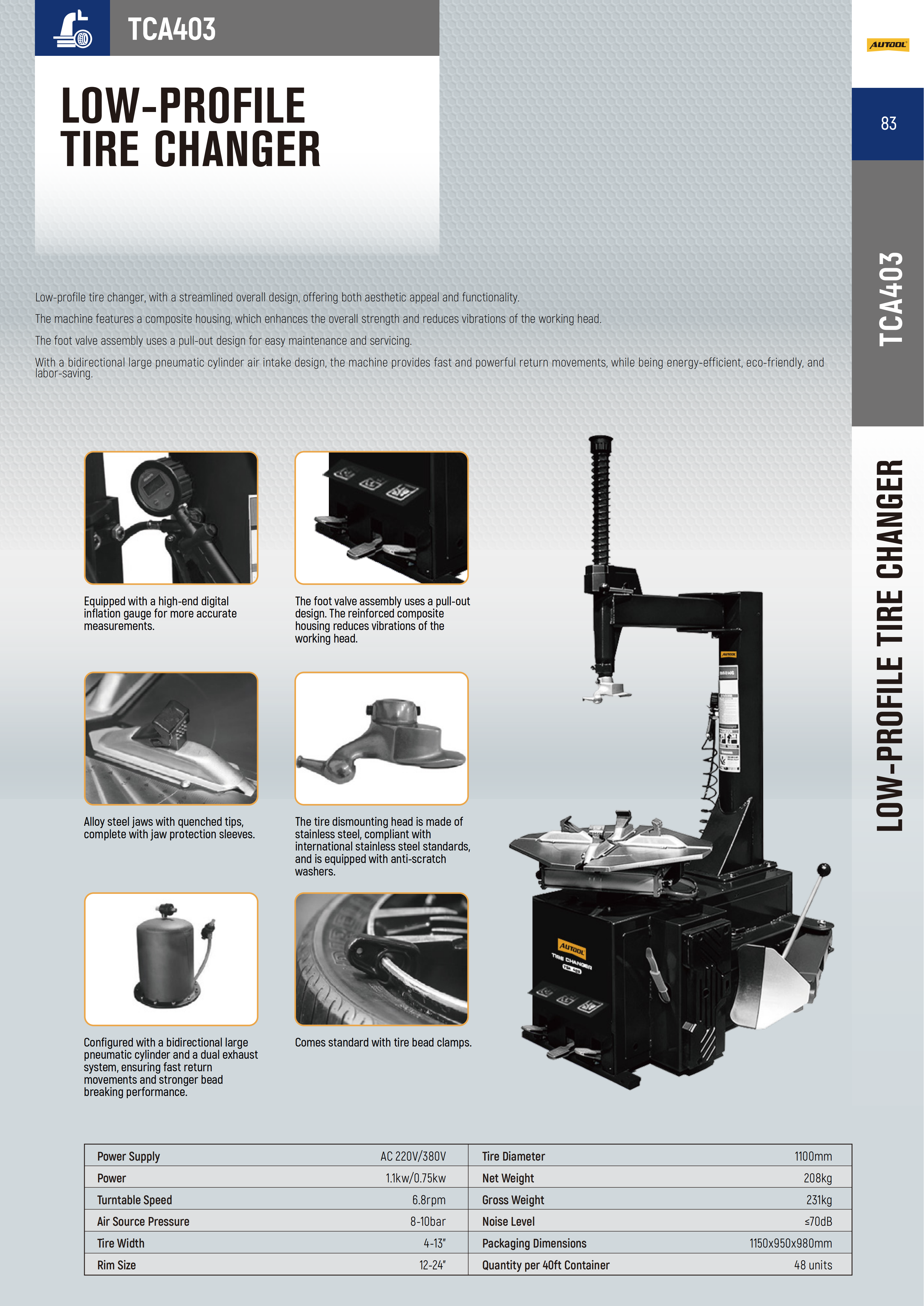
The current product record highlights Low-profile tire service, Protected wheel contact points, Controlled bead breaking, Inflation monitoring, TCA404 auxiliary arm. Confirm each relevant control on the physical unit before use; related AUTOOL models can look similar while using different ranges, air sources or operating modes.
| Specification or function | Current model |
|---|---|
| Power Supply | AC 220V/380V |
| Model Difference | TCA403 standard swing arm; TCA404 adds auxiliary swing arm |
| Motor Power | 1.1kW/0.75kW |
| Turntable Speed | 6.8rpm |
| Air Source Pressure | 8-10bar |
| Tire Width | 4-13in |
| Rim Size | 12-24in |
| Maximum Tire Diameter | 1100mm |
| Noise Level | ≤70dB |
The current exact-product records list 12-24 inch rims, 4-13 inch tire width, up to 1100mm tire diameter, 6.8rpm turntable speed and 8-10bar supply air. These machine capacities are not permission to service every wheel in that range or to inflate to the air-supply pressure. Tire, rim, TPMS, vehicle and workplace instructions may impose lower limits. The delivered control labels govern pedal and arm operation; do not borrow a mapping from another changer.
How to use the TCA403/TCA404
Step 1: Accept only a commissioned machine and a trained operator
Confirm the data plate and delivered controls identify the exact TCA403/TCA404 variant, and confirm the machine has been installed, commissioned and inspected for the site supply and air system. The TCA403 is the standard swing-arm configuration; the TCA404 adds an auxiliary swing arm for more controlled low-profile bead handling. Installation, wiring, internal adjustment and repair belong to qualified service personnel, not this routine operating workflow.
Before moving on, confirm the exact machine variant is commissioned, every wheel-contact protector is intact, the assembly is serviceable and the valve/TPMS position has been marked; bead breaking must wait until the valve core is removed and zero pressure is verified.
Step 2: Inspect every wheel-contact and safety component
Disconnect or isolate the machine as the workplace procedure requires for the pre-use inspection. Check the jaw sleeves, mounting-head anti-scratch washers, bead-breaker pad, turntable, foot controls, hoses, gauge and guards for wear, contamination, leakage or looseness. Replace worn protective pieces before an alloy wheel is clamped.
Step 3: Identify the wheel, tire and TPMS before deflation
Record tire size, rim construction, directional or asymmetric markings and the valve/TPMS position. Inspect for a cracked or bent rim, damaged bead, severe sidewall damage, previous repair or corrosion. Confirm the assembly falls within the stated 12-24 inch rim, 4-13 inch tire-width and 1100mm tire-diameter boundaries; stop for an uncertain or non-serviceable assembly.
Step 4: Remove the valve core and prove zero pressure
Secure the wheel in the designated deflation area, remove the valve cap and valve core with eye protection, and let the tire deflate completely. Confirm zero pressure independently and keep the valve/TPMS location visible. Never use the bead breaker on a pressurized tire.
Step 5: Lubricate and break both beads under control
Apply an approved tire-mounting lubricant to the bead and rim contact area. Position the bead-breaker shoe clear of the valve and TPMS sensor, keep hands and body out of the pinch zone, then apply one controlled stroke. Rotate the wheel and repeat around both sides as needed; do not force one stuck point or let the shoe contact the rim face.
Step 6: Clamp the rim with its finish protected
Choose the clamping method permitted by the delivered machine and the wheel-service procedure, then center and secure the wheel on the turntable. Confirm every jaw contacts evenly through an intact protector and the rim cannot rock. Do not infer an inside- or outside-clamping limit from another tire changer.
Step 7: Position and lock the mounting head
Bring the mounting head to the rim, establish the delivered clearance and lock it before rotation. Confirm the head protector or anti-scratch washer is intact and the head cannot scrape the wheel. On an equipped variant, position the auxiliary arm to support the bead without trapping a hand or loading the TPMS area.
Step 8: Demount the upper bead with minimal pry force
Keep the lubricated bead in the drop center opposite the mounting head, orient the valve and TPMS according to the exact wheel procedure, and use the approved lever or tool path with the least force needed. Rotate the turntable only after hands, loose clothing and tools are clear. Stop if the bead binds, the rim moves or the head approaches the finish.
Step 9: Demount the lower bead and remove the tire
Reposition the lower bead at the mounting head, keep the opposite side in the drop center and repeat the controlled rotation. Support the tire as it clears the rim so it cannot fall, pull the sensor or strike the controls. Return the turntable to rest before lifting the tire away.
Step 10: Inspect the bare rim, tire beads and TPMS
Clean and inspect both bead seats, flanges, tire beads and the valve/TPMS assembly. Resolve corrosion, a sharp edge, cracked rim, deformed bead, incorrect repair or damaged sensor before mounting. Confirm the replacement tire's size, load, speed, rotation and rim compatibility from its own service information.
Step 11: Lubricate and mount the lower and upper beads
Apply approved lubricant evenly without flooding the TPMS or wheel. Align directional and balance markings as required, place the lower bead in the drop center and rotate it past the protected mounting head. Repeat for the upper bead while the auxiliary arm, when fitted, keeps a stiff low-profile or run-flat bead controlled. Stop and reset if force rises or the bead climbs out of the drop center.
Step 12: Seat and inflate from outside the trajectory
Remove loose tools, release any auxiliary contact that is not required, and use the workplace's approved restraint and inflation procedure. Keep your head and body out of the tire's trajectory and never lean over the assembly. Inflate only within the lowest limit specified by the tire, rim, machine and workplace; if the bead does not seat promptly, stop, fully deflate, relubricate and reposition instead of adding pressure. Neither the TCA403 nor the TCA404 product record identifies an independent bead-blaster system, so do not improvise that function.
Step 13: Set final pressure, release and verify the assembly
After both beads are correctly seated, set the vehicle-specified cold pressure, apply leak detection at both beads and the valve, and confirm the TPMS remains intact. Return the controls to rest, unclamp without marking the rim, then balance the assembly and complete the vehicle-specific torque, pressure and TPMS checks before service.
Before closing the tire service, verify both bead-reference lines are even, both beads and the valve are leak-free, final cold pressure is correct, the rim is unmarked and the balanced assembly passes its TPMS and vehicle checks.
Read and verify the result
A completed tire change should leave both beads uniformly seated, the rim finish unmarked, the valve and TPMS intact, and the assembly holding the vehicle-specified cold pressure. Rotate and inspect the complete circumference on both sides. A bead that appears uneven, a pressure loss, sensor warning, new sidewall damage or a wheel that will not balance is a stop condition—not a cosmetic detail.
- Confirm the bead-reference line sits evenly around both rim flanges; an uneven line can indicate incomplete seating.
- Apply leak-detection solution to both beads and the valve area, then correct the cause of any bubble before installation.
- Compare the rim face and flange with the pre-service inspection so new marks or deformation are not missed.
- Balance the assembly after mounting; the tire changer does not replace wheel balancing or runout diagnosis.
- Verify final cold pressure, valve-core sealing and TPMS operation with the vehicle procedure after installation.
Stop immediately if the tire is not fully deflated, a jaw or mounting head can contact an unprotected finish, the bead binds, the rim shifts, the valve or TPMS enters the tool path, a protector is worn, air leaks from the machine, or the bead will not seat at the permitted pressure. Return the controls to rest, isolate motion and fully depressurize before correcting the setup.
Common mistakes and care
- Use this machine only after professional installation, commissioning and operator training for the exact delivered controls.
- Fully deflate the tire and verify zero pressure before bead breaking or demounting.
- Keep valve and TPMS position visible, use approved tire lubricant and replace worn rim-protection pieces before work.
- Keep hands clear of the bead breaker, jaws, turntable, mounting head and auxiliary-arm pinch zones.
- Stand outside the tire trajectory during inflation and never exceed the lowest tire, rim, machine or workplace pressure limit.
- Stop for a binding bead, moving rim, damaged protector, leak, unexpected movement or any uncertainty about the wheel assembly.
- Do not place the bead-breaker shoe beside the valve/TPMS or let it strike the rim face.
- Do not use dry soap, petroleum grease or an unidentified chemical in place of approved tire-mounting lubricant.
- Do not compensate for poor drop-center positioning by adding pry force or continuing turntable rotation through a bind.
- Do not assume nylon sleeves and anti-scratch washers make wheel damage impossible; condition, clearance and technique still control contact.
- Do not lean over the wheel, hold the bead by hand or continue adding pressure when seating stalls.
Frequently asked questions
What is the difference between TCA403 and TCA404?
The TCA403 is the standard swing-arm configuration; the TCA404 adds an auxiliary swing arm. Do not infer the auxiliary-arm procedure on a TCA403.
Do protective sleeves guarantee a scratch-free wheel?
No. Intact jaw sleeves and mounting-head protectors reduce direct metal contact, but cleanliness, clearance, clamping, lubrication and operator technique still determine whether the finish is protected.
What should I do when the bead will not seat?
Stop adding pressure, keep clear until the assembly is fully deflated, then inspect bead and rim condition, relubricate and reposition. Never exceed the lowest tire, rim, machine or workplace pressure limit to force seating.
Final TCA403/TCA404 checklist
- Exact variant, commissioning status and pre-use machine inspection confirmed
- Tire, rim, direction markings, damage and valve/TPMS position recorded
- Valve core removed and zero pressure verified before bead breaking
- Jaw, head and bead-breaker protection intact; approved lubricant used
- Both beads mounted without binding, uncontrolled pry force or rim movement
- Bead seating even; both beads and valve leak-free at final cold pressure
- Assembly balanced; valve, TPMS, wheel torque and vehicle pressure checks completed
The TCA403/TCA404 works best when force is replaced by control: deflate completely, protect every wheel contact, keep the bead lubricated and in the drop center, and stop before a bind becomes damage. Safe inflation and a full leak, balance and TPMS verification close the job.











Comments 0
Questions, fixes, and real-world diagnostic notes from readers.
Be the first to share a diagnostic result or ask a follow-up question.