
How to Use FXTUL F803 Dual Mode for EVAP and Intake Leak Tests

The FXTUL F803 smoke leak detector can supply air, show pressure and flow, and add visible smoke, but EVAP and intake testing are not the same procedure. A reliable diagnosis begins by defining one vehicle-supported boundary, testing it with air first and adding smoke only after the adapter, valve state and pressure limit are known. Finish that system and restore it before building the other test boundary.
Quick answer: For EVAP, use the vehicle-approved service entry and vent/purge state at the vehicle’s specified very low pressure. For intake, keep the engine off and cool, isolate only the specified intake section and seal a suitable entry with the cone or bladder. In either job, stabilize the F803 in air mode, record pressure and flow together, correct setup leaks, then activate smoke and trace the first unintended exit. Never copy pressure, caps or valve positions from one system to the other.
In this guide
Build two separate test boundaries
The F803 is the source and observation tool. The vehicle procedure defines what may be pressurized. An EVAP system contains designed vapor paths and valves that may be open in a key-off state; an intake system contains throttle, crankcase, brake-booster, vacuum and turbo branches whose normal state depends on the engine and test objective.
Write an EVAP setup and an intake setup as separate jobs. Give each one its own entry point, intentionally open paths, required caps, valve commands, maximum pressure and verification method. A cone that seals an intake duct does not make a fuel-filler neck or EVAP service port an approved entry, and a commanded EVAP vent state says nothing about an intake valve.
| Decision | EVAP test | Intake test |
|---|---|---|
| Entry point | Approved EVAP service port or vehicle-specified adapter | Specified intake duct, boot or service opening |
| System state | Vehicle-defined vent and purge-valve state | Engine off/cool; throttle and branch state defined for the selected section |
| Pressure limit | Exact vehicle EVAP procedure | Exact vehicle/intake procedure and component limits |
| Designed exits | Vent, cap, canister or valve paths identified before testing | Crankcase, brake-booster, vacuum, exhaust/turbo or throttle paths identified before testing |
| Final proof | Same-boundary retest plus required monitor/scan checks | Same-boundary retest plus symptom, trim/boost or operational checks as applicable |
For fluid filling, control identification, battery connection, bladder care, storage and full machine setup, use the complete FXTUL F803 setup and control guide. The procedure below concentrates on keeping EVAP and intake diagnosis separate.
Before you start
- Confirm the exact vehicle, symptom, fault codes and the single system you will test first.
- Obtain vehicle service information for the entry point, valve state, designed openings and maximum permitted pressure.
- Switch the ignition and engine off; allow the intake, exhaust and turbo area to cool before installing adapters.
- Inspect the F803 hose, power lead, cone, bladder, flow-control valve, gauge and flow meter.
- Keep the F803 upright and use only a charged 12-volt vehicle battery with red to positive and black to negative.
- Check the smoke-medium level through the window and follow the manual’s level and fluid requirements.
- Prepare a test record for boundary, entry, valves, caps, control position, air trend, first smoke exit and retest.
Do not begin if the system pressure limit or required valve state is unknown. The F803’s maximum output is not permission to pressurize a vehicle system to that value.
FXTUL F803 EVAP and intake leak-test workflow
Step 1: Prepare the F803 once for both jobs
Install the hook, connect the smoke hose and machine-side power lead, and keep the unit standing or hanging vertically. Confirm the fluid level rather than adding a guessed fixed volume. Support the hose so it cannot pull an adapter sideways.
With the vehicle off, connect the red clamp to battery positive and black to negative. Power should start the air source without requiring smoke. Begin with the flow-control valve conservatively restricted and increase delivery only within the current vehicle procedure.
Step 2: Document the first test boundary
Choose EVAP or intake; do not connect both. Draw or list the path from the planned entry to every branch, valve and designed opening. State what is included, what is excluded, and how the vehicle procedure puts each controllable valve in the required position.
Record the permitted pressure and planned observation time. If a scan tool is needed to command an EVAP vent valve or another component, verify the command and vehicle state before admitting air.
Step 3: Configure an EVAP test from vehicle information
Use the specified EVAP service port or approved adapter. Confirm fuel level and temperature prerequisites when the vehicle procedure requires them. Identify the purge path, canister, vent path, filler cap and any rollover or pressure-relief device before sealing anything.
Place the vent and purge valves only in the states required for that vehicle. Do not clamp, plug or command a line merely because it releases air; it may be a designed path or protective device.
Step 4: Run the EVAP air-only stage
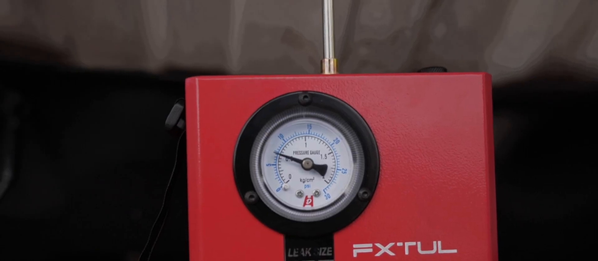
Connect the F803 nozzle to the approved EVAP adapter with smoke off. Admit air gradually while remaining within the vehicle’s very-low-pressure limit. Check the adapter first, then observe the pressure gauge and flow meter together after the setup stabilizes.
If pressure does not build or flow remains high, inspect the service adapter, fuel cap, temporary caps, vent command and purge isolation before calling a vehicle component faulty. Record the paired trend under the unchanged setup.
Step 5: Add smoke to locate the EVAP exit
Press Start/Stop and confirm visible output at the nozzle before reconnecting it without changing the EVAP boundary. Use a bright lamp and inspect in path order from the adapter through hoses, canister connections, cap seal, tank-area joints and the commanded vent path.
Mark the first repeatable unintended smoke exit before haze spreads. Confirm it is not an adapter leak, designed vent or smoke travelling along a surface from another joint. Stop smoke manually when the inspection is complete; the machine also has a five-minute automatic smoke cycle.
Step 6: Close and restore the EVAP job
Remove pressure and smoke before disconnecting the adapter. Return commanded valves to normal, remove every temporary cap or clamp, and restore the service port and fuel cap exactly as specified.
If a repair is made, recreate the same EVAP entry, valve state, caps, flow-control position and observation time. Confirm that the original exit is gone and complete any required scan-tool monitor, code or drive-cycle check.
Step 7: Create a new intake test plan
Erase no settings and reuse no assumptions from EVAP. Define the exact intake section related to the symptom: naturally aspirated ducting/manifold, a selected vacuum branch or a supported low-pressure section of a boosted-air path. Keep the engine off and the entire work area cool.
Identify throttle state, crankcase ventilation, brake-booster line, vacuum actuators, sensor openings and turbo/exhaust connections that belong to the boundary. Follow component pressure limits and the vehicle procedure; do not pressurize across an unsuitable sensor, diaphragm or turbo seal.
Step 8: Seal the specified intake entry
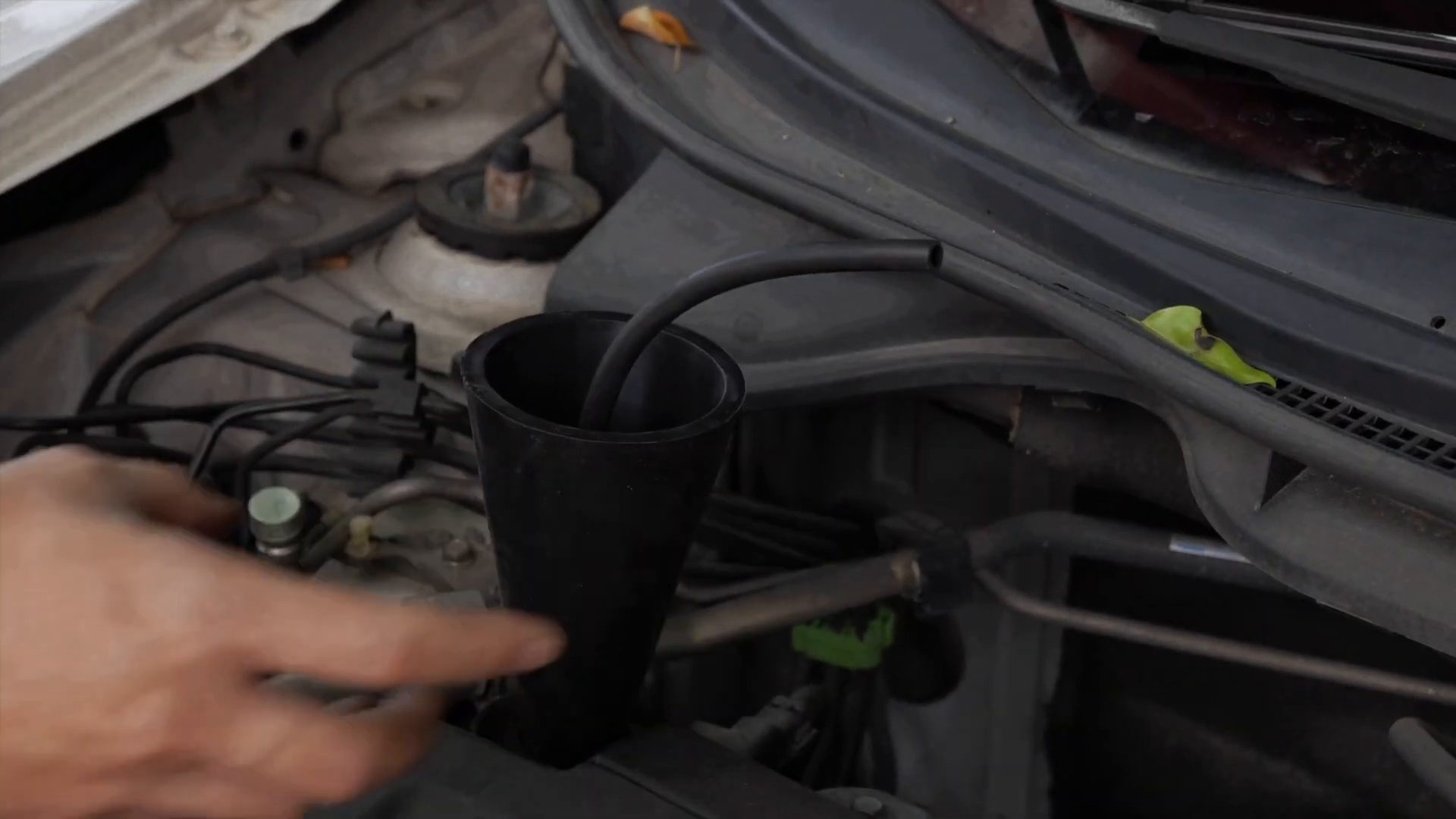
Remove only the duct or connection selected by the procedure. Clean the contact surface and inspect for sharp edges. Seat the cone squarely in a suitable round opening, or place the universal bladder in a clean irregular opening and inflate it only until secure.
Support the hose and verify the adapter with light movement. If the bladder is used, keep it away from sharp or corrosive surfaces and plan to release it fully through its relief valve before removal.
Step 9: Run the intake air-only stage
Insert the nozzle with smoke off and admit only the pressure permitted for the selected intake section. Let the setup stabilize for about 30 seconds, as described in the F803 manual, while checking the cone or bladder and every temporary cap for leakage.
Record pressure and flow together at the same control position. A low or changing gauge with continuing flow can come from an open branch, incorrect throttle or valve state, adapter leak or the vehicle fault. Correct setup causes before moving to smoke.
Step 10: Add smoke and inspect the intake path
Start smoke, confirm output at the nozzle and return it to the stable adapter. Inspect from the entry outward: duct seams, clamps, boots, sensor seals, throttle-body joint, manifold gasket, vacuum hoses and the branches included in the written boundary.
Observe from more than one angle and mark the first unintended exit. Smoke visible at a crankcase, throttle or other branch is not automatically a failed part; compare its location with the system diagram and the state of connected valves.
Step 11: Repair and repeat the same intake setup
Confirm the leaking component or seal rather than replacing the nearest visible part. Smoke can travel along a hose, casting or wiring loom. Use the specified repair, fastener sequence and torque, then rebuild the original boundary.
Repeat the air trend and a shorter smoke inspection with the same entry, caps, valve state, flow-control position and observation time. Finish with the operational evidence appropriate to the original symptom, such as stable fuel trims, restored boost control or a corrected idle.
Step 12: Shut down, clear residual smoke and store upright
Press Start/Stop if the working-cycle light remains on and allow the air source to push residual smoke from the nozzle. Remove the nozzle, release any bladder completely, disconnect battery power and restore all ducts, clamps, caps and connectors.
Let the F803 cool, inspect the hose and adapters, and store it standing or hanging upright. Preserve the two records separately so a future retest can reproduce the correct EVAP or intake conditions.
How to interpret the two tests
A result is useful only when it belongs to a named boundary and survives a same-condition repeat.
| Observation | First check | Valid next step |
|---|---|---|
| Pressure stays low and flow continues | Adapter, caps, designed exits and commanded valve state | Correct setup; then reproduce and trace with smoke |
| Pressure stabilizes and continuing flow decreases | Control position and observation time are unchanged | Compare with the vehicle procedure; do not invent a pass value |
| Smoke appears at the entry | Cone, bladder or service-adapter seal | Stop interpretation and reseal the entry |
| Smoke appears at a vehicle joint | Whether the path is designed in the current state | Confirm the source from another angle and inspect the complete joint |
| Repair changes the result | Retest conditions match the original | Complete system-specific operational or monitor verification |
Never use the F803’s machine-output specification as a vehicle test target. EVAP components are especially pressure-sensitive, and intake branches can include diaphragms, sensors and seals with their own limits. The exact vehicle procedure always controls pressure and valve state.
Common mistakes
- Treating EVAP and intake as one connected test boundary.
- Using the same pressure, adapter or valve state for both systems.
- Starting smoke before confirming that the entry and temporary caps seal in air mode.
- Calling a designed vent or open branch a leak.
- Reading gauge pressure without the corresponding flow and control position.
- Changing the setup between the original test and repair verification.
- Removing an inflated bladder or laying the F803 on its side.
Frequently asked questions
Can I use the same F803 pressure for EVAP and intake testing?
No. The exact vehicle and component procedure defines the safe pressure for each boundary. The machine’s output limit is not a universal setting.
Should I start with air or smoke?
Start with air. It lets you confirm the adapter, caps, valve state and paired pressure/flow trend before smoke obscures the area.
Does a high flow-meter reading prove a large leak?
Not by itself. Flow depends on the control position, test volume, adapter seal, designed openings and valve state. Compare paired trends only under a controlled setup.
Can I use the cone adapter on an EVAP filler neck?
Only when the exact vehicle procedure approves that entry and adapter method. A cone shown at an intake opening is not automatic approval for an EVAP filler neck.
Why must the repair test use the same setup?
Changing the entry, caps, valves, pressure control or observation time changes the boundary, so the before-and-after readings no longer provide a valid comparison.
Dual-mode leak-test record
- Only one named system was connected at a time.
- Entry, valves, caps, designed openings and pressure limit came from vehicle information.
- F803 remained upright and used a charged 12-volt vehicle battery.
- Air-only pressure and flow were recorded before smoke.
- The first unintended smoke exit was confirmed against the system diagram.
- Repair verification repeated the same boundary and settings.
- Every adapter, cap, clamp, duct and commanded valve was restored.
The F803 becomes more useful when its dual-mode features support disciplined system boundaries. Keep EVAP and intake as separate jobs, establish each one with air, use smoke to localize rather than guess, and prove the repair under the same recorded conditions.








Comments 0
Questions, fixes, and real-world diagnostic notes from readers.
Be the first to share a diagnostic result or ask a follow-up question.