
How to Use the AUTOOL OD760 Oil Drainer and Extractor Step by Step

The AUTOOL OD760 combines a pneumatic vacuum extractor, a 20 L gravity catch pan, a 10 L transparent measuring cup, an 80 L waste-oil tank and a drawer-based oil-service workstation. Those features share one mobile cabinet, but they do not share one pressure or valve sequence. Choose either vacuum extraction or gravity draining for the vehicle, transfer cup oil into the tank, then treat storage-tank emptying as a separate low-pressure operation.
For vacuum extraction, use dry regulated air within 6–8 bar, maintain a stable supply of at least 7 bar at the machine under flow, and build only the manual’s 0.06–0.08 MPa vacuum indication. For storage-tank discharge, use only 0.6–0.8 bar. Keep waste engine oil within a conservative 40–60°C range because the current product guidance uses that range and the manual warns that oil above 60°C may damage components. Keep the engine off, never force a probe and never use OD760 for brake fluid, gasoline, diesel, methanol, ketone or another flammable liquid.
Updated August 28, 2026.
In this guide
- Choose one OD760 oil-removal path
- Prepare the workstation, vehicle and air supply
- AUTOOL OD760 step-by-step procedure
- Vacuum extraction through the measuring cup
- Gravity draining through the catch pan
- Empty the OD760 storage tank
- Troubleshoot OD760 without increasing pressure
- What a complete OD760 job looks like
Choose one OD760 oil-removal path
| Vehicle and workshop condition | Correct path | Main control |
|---|---|---|
| The vehicle procedure approves top-side oil extraction through an identified tube | Vacuum extraction into the measuring cup | Correct probe, dry 6–8 bar air and 0.06–0.08 MPa vacuum indication |
| The sump drain point is the approved access and the vehicle can be lifted safely | Gravity draining through the catch pan | Mechanically locked lift, locked casters and centered pan |
| The probe route, insertion depth or vehicle compatibility is uncertain | Stop and consult vehicle service information | Never force or improvise an extraction route |
| Waste oil is above 60°C or below the usable 40°C condition | Correct the temperature before collection | Protect the cup, hoses and operator from heat |
| The measuring cup approaches its warning line | Stop extraction and transfer oil to the tank | The nominal 10 L capacity is not a fill target |
| The 80 L tank lacks verified free capacity | Empty it into an approved container first | Leave headroom and keep the discharge hose controlled |
Prepare the workstation, vehicle and air supply
Have the exact vehicle oil-service procedure, approved lift instructions for gravity drainage, the correct extraction probe or drain-plug tools, any specified replacement seal, a calibrated torque wrench, gloves, safety goggles and absorbent material. OD760’s included drawers can organize tools, but a supplied tool is not automatically correct for every vehicle. Use only the size and torque method required by the vehicle manufacturer.
For vacuum generation, use dry shop air through a 10 mm supply line. Regulate the source within 6–8 bar and confirm that pressure at the machine remains at least 7 bar while air is flowing, without exceeding 8 bar. For tank discharge, prepare a separate 0.6–0.8 bar regulated setting, an approved receiving container with enough free capacity and a secured drain-hose route.
AUTOOL OD760 step-by-step procedure
Step 1: Confirm the exact OD760 configuration
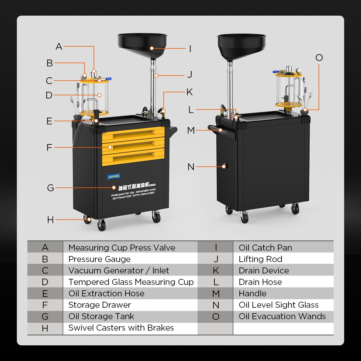
Check the model label and locate the measuring-cup press valve, vacuum gauge, vacuum generator and inlet, tempered measuring cup, extraction hose and valve, probe set, 20 L catch pan, lifting rod, drain device, oil-discharge hose and valve, tank air-inlet valve, safety and check-safety valves, oil-level sight window, 80 L tank, drawers, handle and braking casters.
Stop: If the components or valve positions differ, obtain the instructions for that exact revision before connecting air.
Step 2: Choose vacuum extraction or gravity draining
Use vacuum only when vehicle service information approves top-side extraction and defines the access route. Use gravity drainage when the sump plug is the approved service point and a suitable lift can support the vehicle mechanically.
Completion check: The selected path, expected oil quantity, access point and completion criterion are known before the machine is positioned.
Step 3: Confirm the liquid, temperature and engine state
Use OD760 only for identified waste engine oil. Bring the oil into the conservative 40–60°C range by the vehicle-approved method, then switch the engine off and prevent unintended starting. Remove smoking, sparks and open flames from the area.
Stop: Do not collect brake fluid, gasoline, diesel, a methanol- or ketone-containing liquid, another flammable liquid or an unidentified workshop fluid.
Step 4: Verify measuring-cup, tank and receiver capacity
Read the cup scale and tank sight window. Estimate the vehicle quantity and leave headroom in both vessels. If the tank needs emptying, confirm that the downstream container can receive the complete planned volume without overflowing.
Common mistake: Treating 10 L or 80 L as a working fill target leaves no margin for movement, foaming or an inaccurate vehicle quantity.
Step 5: Inspect every OD760 control and fluid path
Inspect the cup, lid, gauge, transparent hose, vacuum generator, extraction hose, probes, pan, lifting rod, tank, level window, air and oil valves, safety devices, drain hose, fittings, handle, drawers and caster brakes. No cup may be cracked, no hose kinked and no joint may leak air or oil.
Stop: Isolate a damaged machine. Do not tape a hose, bypass a valve, defeat a safety device or operate with a sticking drawer or caster brake.
Step 6: Assemble the wheels, cup, hose, rod and pan
Attach the wheels. Rotate the measuring-cup assembly clockwise onto the tank positioning seat, orient and secure it, then attach the transparent hose. Fit the lifting rod and pan clockwise, keep the rod perpendicular to the cabinet, turn clockwise to lock its height and counterclockwise to release it.
Completion check: All assemblies are secure and the rod, pan or hose cannot interfere with the drawers or controls.
Step 7: Stabilize the mobile workstation
Close every drawer, stow loose tools and roll OD760 by its handle rather than its lifting rod. Park it on level floor, apply the caster brakes and keep the operator’s exit path clear. Open only the drawer needed for the current vehicle task and close it before moving the cabinet.
Common mistake: Moving the machine with an open loaded drawer shifts its center of gravity and can spill tools into the work area.
Vacuum extraction through the measuring cup
Step 8: Prepare the approved vehicle access route
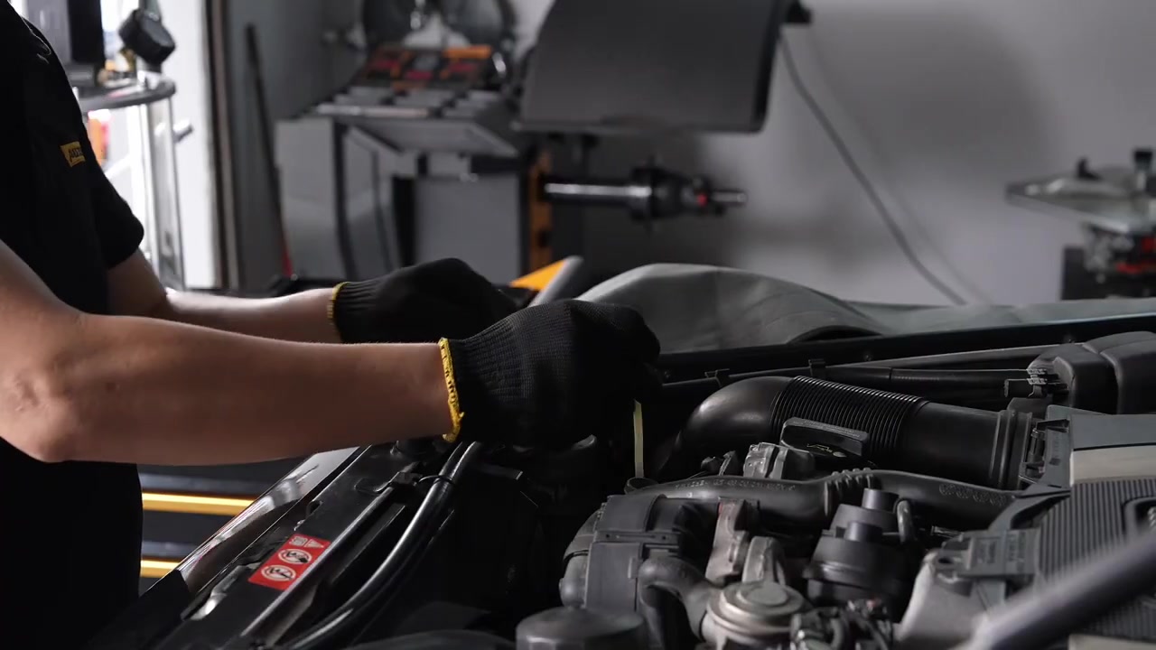
Follow vehicle service information for filler-cap, dipstick or service-tube access. Protect every opening from dirt and identify the correct probe diameter, length and insertion depth before touching the vehicle.
Stop: If no approved extraction route is specified, switch to the approved gravity procedure rather than guessing.
Step 9: Close the cup valve and extraction-hose valve
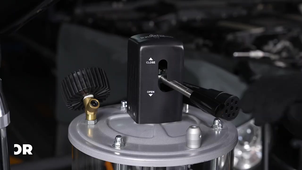
Press and rotate the measuring-cup valve into its middle slot, the closed position. Close the oil-extraction hose valve, attach the correct clean probe and route the hose without a kink. Confirm that the cup has enough free capacity.
Completion check: The cup is isolated for vacuum generation and the probe-side oil path remains closed.
Step 10: Connect dry regulated air to the vacuum inlet
Connect the 10 mm dry-air supply to the measuring-cup air inlet. Hold the source within 6–8 bar and verify a stable minimum of 7 bar at the machine under flow. This high-pressure supply belongs only at the vacuum generator; it must never be applied directly as the storage-tank discharge pressure.
Stop: Close and disconnect air if pressure is unstable, exceeds 8 bar, a leak appears or the cup or gauge moves abnormally.
Step 11: Build only 0.06–0.08 MPa of vacuum indication
Operate the vacuum control while watching the negative-pressure gauge. Stop pressurization when the gauge indication reaches the manual’s 0.06–0.08 MPa vacuum band. Let it stabilize and listen for leakage before opening the oil path.
Common mistake: Adding more supply pressure to speed up extraction can hide a blocked probe and exceed the documented operating range.
Step 12: Insert the probe without force
Guide the selected probe through the approved vehicle tube to the specified depth. Keep it away from hot and moving parts and stop immediately at unexpected resistance. Do not bend, twist or use the probe to search blindly inside the sump.
Completion check: The probe is stable, clean, unkinked and positioned only as the vehicle procedure permits.
Step 13: Open the extraction valve and monitor the cup
Open the extraction-hose valve gradually. Watch oil enter the transparent cup, track the gauge and inspect each connection. Stay at the machine throughout extraction and use the vehicle procedure—not a marketing time estimate—to decide when the sump is complete.
Stop: Close the hose valve if the cup approaches its warning line, flow contains an unexpected liquid, vacuum becomes unstable or any leak appears.
Step 14: Stop vacuum and remove the probe cleanly
At the completion condition, close the extraction-hose valve and disconnect the air supply. Let hose flow settle, then withdraw the probe slowly while controlling drips. Wipe it, check that it is intact and restore the vehicle opening as specified.
Completion check: No retained suction, dripping hose or foreign material remains at the vehicle access point.
Step 15: Transfer measuring-cup oil into the tank
When oil is in the cup—or before it reaches the warning line—press and rotate the cup valve into its top-left or top-right open slot. Watch the oil drain into the storage tank and stop if available tank capacity becomes uncertain. After the cup is empty, its drain path may remain open only during unpressurized standby.
Stop: Return the measuring-cup valve to the middle closed slot before storage-tank pressurization.
Gravity draining through the catch pan
Step 16: Lift and mechanically secure the vehicle
Use approved lifting points, remain within lift capacity and engage every required mechanical lock. Verify stability before anyone or OD760 moves under the vehicle. Lower the pan enough for clear positioning.
Stop: Never work under a vehicle supported only by a jack, hydraulic pressure or an unverified lift position.
Step 17: Position and lock the catch pan
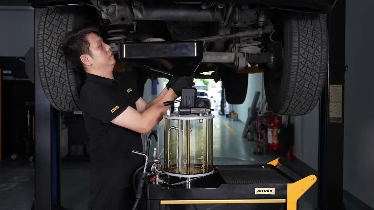
Roll the closed-drawer machine by its handle, apply the caster brakes and raise the pan beneath the drain point. Center it for the initial oil-flow arc and final drip, then lock the rod clockwise without letting the pan contact or support the vehicle.
Completion check: The cabinet cannot roll or tip, and oil has a clear contained path through the screened pan into the tank.
Step 18: Remove, drain and reinstall the sump plug
Keep your body away from the warm-oil path, remove the drain plug with the vehicle-specified tool and monitor the pan, screen, tank level and floor. At the specified drain condition, inspect the plug and threads, fit the required seal and tighten to the manufacturer’s torque.
Common mistake: Choosing a wrench from the drawer by appearance rather than exact fit can damage the plug before the oil service begins.
Step 19: Finish the vehicle and clear the lift zone
Lower and lock the catch pan, move OD760 clear by its handle and complete the filter, refill, level and leak checks required for the vehicle. Clean and return tools to their assigned drawer positions before lowering the lift.
Completion check: The vehicle is leak-free, the cabinet is clear of the lift and every drawer is closed.
Empty the OD760 storage tank
Step 20: Isolate the cup and prepare a contained discharge route
Secure the oil-discharge hose in an approved receiving container with enough free capacity. Put the measuring-cup valve in its middle closed slot, close the oil-discharge valve and close the tank air-inlet valve. Confirm the tank, level window, hose and both safety devices are undamaged.
Stop: Do not pressurize a leaking tank, blocked hose, damaged valve or unsecured receiving container.
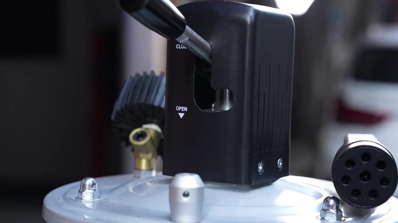
Step 21: Pressurize only within the 0.6–0.8 bar discharge range
Connect a separately regulated air supply to the tank inlet, then open the inlet valve promptly to begin pressurization. Keep actual tank-discharge pressure within 0.6–0.8 bar. When the manual’s tank safety valve rises and closes the incoming path, stop adding pressure and prepare to discharge.
Stop: If the check-safety valve releases and closes the inlet, or any abnormal pressure, sound, movement or leak appears, isolate the air. A safety device is not a normal regulator or permission to continue.
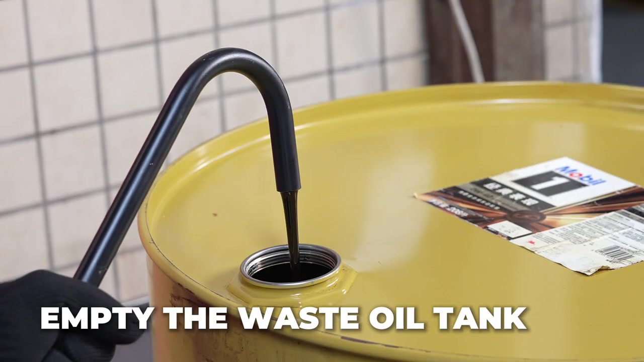
Step 22: Open the oil valve, depressurize and store
Open the oil-discharge valve slowly and monitor the hose, receiving container, tank level and fittings until flow is complete. Disconnect the air source, then release remaining tank pressure through the manual’s inlet-valve procedure before touching any fitting. Close and secure the oil path, clean spills, inspect the machine and store it dry with the pan lowered, probes protected and drawers closed.
Completion check: OD760 has no retained pressure, cup oil near its warning line, leaking connection, unsecured hose or loose tool, and the waste oil is routed for lawful recycling or disposal.
Troubleshoot OD760 without increasing pressure
If vacuum extraction is slow, close the extraction valve and disconnect air before checking oil temperature, dry-air delivery, probe choice, insertion depth, hose kinks and the vehicle-approved route. If gravity drainage is slow, check the vehicle drain opening and oil condition rather than adding vacuum. If tank discharge slows, close the oil valve, isolate air and fully depressurize before checking the hose, container venting or valve position. A cracked cup, unstable gauge, repeated leak, activated safety device or internal blockage requires qualified service.
What a complete OD760 job looks like
A complete job begins with a closed, stable workstation and one chosen vehicle-oil path. Vacuum extraction uses a correct probe, dry 6–8 bar supply that remains at least 7 bar under flow, a closed cup valve and only 0.06–0.08 MPa vacuum indication. Gravity draining uses a mechanically locked lift and centered pan. Cup oil is transferred before the warning line. Tank discharge uses an isolated cup, secured receiver and only 0.6–0.8 bar, followed by complete pressure release and clean tool storage.
If your supplied controls, air instructions or valve sequence differ from this guide, use the exact OD760 revision in the AUTOOL manual download center before operating it.











Comments 0
Questions, fixes, and real-world diagnostic notes from readers.
Be the first to share a diagnostic result or ask a follow-up question.