
How to Install and Use the MRCARTOOL M80 GPS/OBD Display

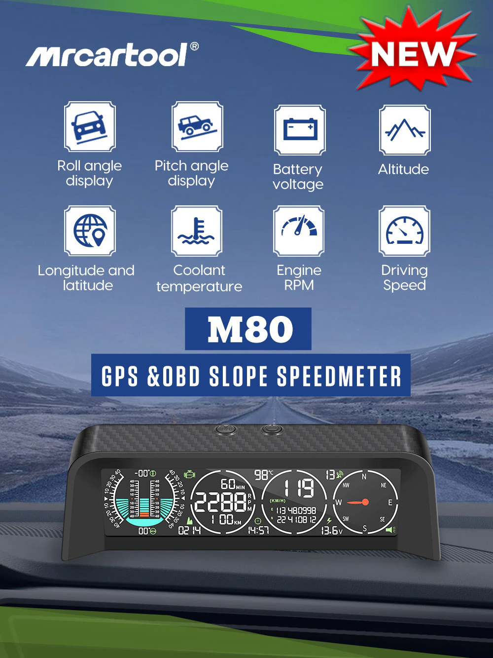
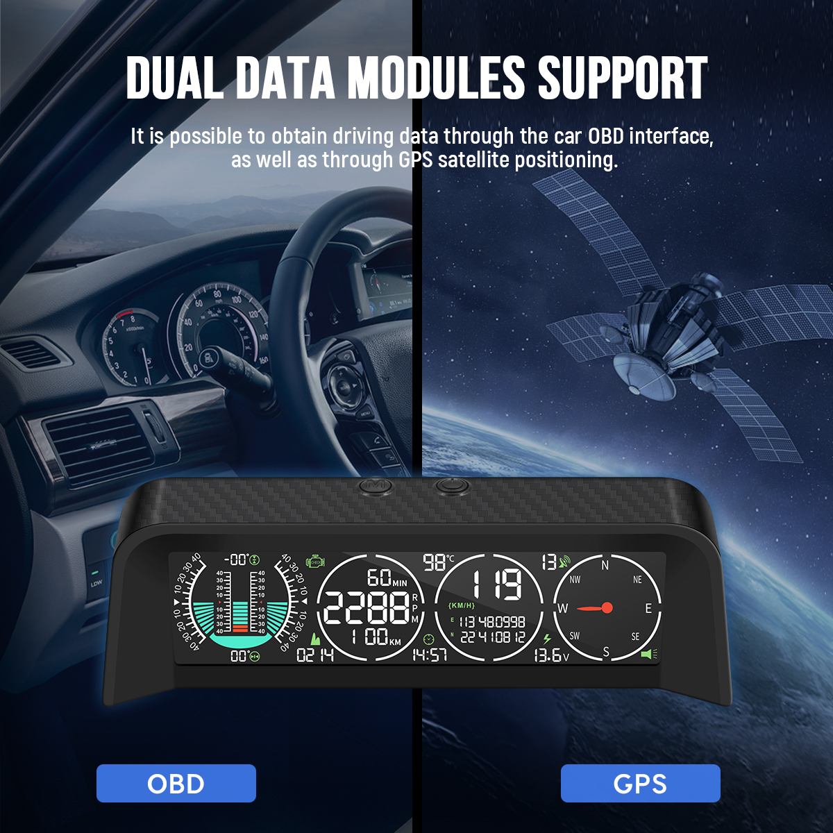
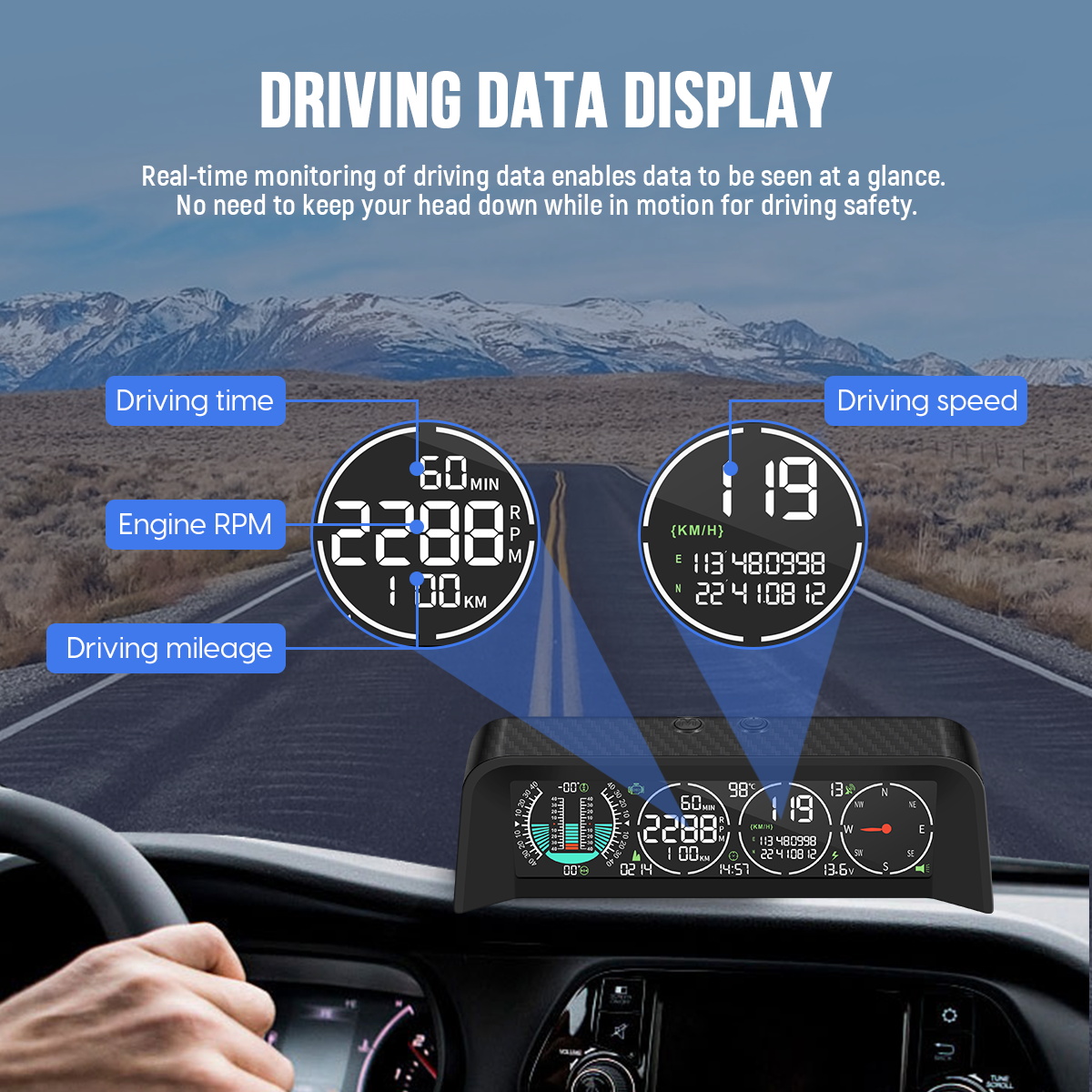
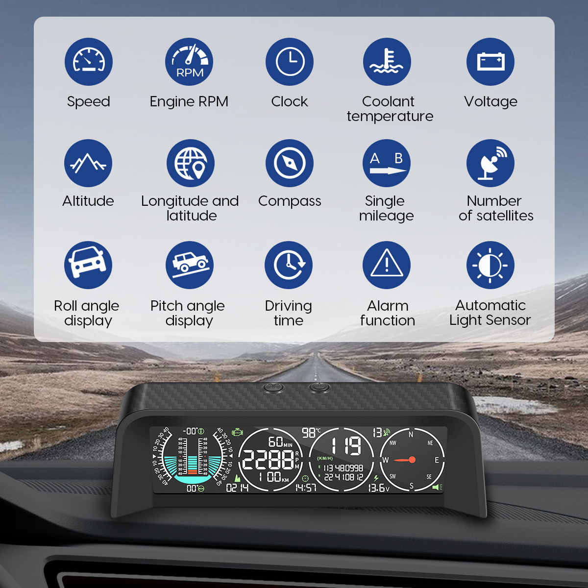
The MRCARTOOL M80 GPS/OBD display combines three information paths on one screen. Its OBD connection can read supported ECU data such as RPM, coolant temperature and synchronized vehicle speed; its GPS/BeiDou receiver provides satellite time, altitude, coordinates, direction and positioning status; its internal angle sensor displays pitch and roll. Correct installation means verifying each path independently instead of assuming every field comes from the same source.
Quick answer: Confirm that the vehicle uses a supported 12/24 V OBD-II data system and that no diagnostic or electrical fault makes accessory connection inappropriate. With the vehicle stationary and ignition off, locate the exact diagnostic connector, inspect it and connect the supplied M80 cable without force. Route the cable outside pedals, steering, knees and airbag zones. Mount M80 horizontally on a rigid dashboard surface, square with the vehicle centerline. Start the vehicle as permitted, confirm the OBD-active icon and plausible RPM/coolant data, then wait outdoors for stable GPS time, satellite count and direction. Drive only after setup is complete and compare OBD speed, GPS behavior and angle response under controlled conditions.
In this guide
Separate OBD, GPS and angle data
The exact page lists nine supported OBD protocols but does not name them. It specifies DC 10–30 V supply, -40°C to 80°C operation, synchronized ECU speed and RPM, DC 5–30 V voltage display with ±0.5 V stated accuracy, and -40° to +40° pitch and roll ranges. GPS figures include one-second refresh, one-second average hot start, 32-second average cold start and ±0.05 km/h stated speed accuracy under suitable conditions.
OBD availability is vehicle-dependent. A physical connector does not guarantee that every displayed PID is supported, and a nine-protocol claim is not universal compatibility. GPS fields can work even if the ECU link does not, while RPM and coolant cannot be created by GPS. Pitch and roll can change even when both data links are absent. This separation is the fastest way to diagnose a blank or implausible field.
Do not connect or route the OBD cable while driving. The diagnostic connector can be near the driver’s knees and pedals. Keep the plug and cable out of all control and airbag zones, never force a damaged or incompatible connector and do not use the M80 during manufacturer programming, network diagnosis or any procedure that requires the DLC to remain dedicated.
Install the OBD cable and display
1. Confirm vehicle and connector suitability
Check the vehicle service information for connector location, system voltage and any restrictions on leaving an accessory connected. M80 accepts DC 10–30 V, but the vehicle still must expose a compatible OBD data path. Hybrid and electric vehicles may have special sleep and high-voltage service requirements even though the diagnostic connector itself is low voltage. Resolve active communication, battery or diagnostic-connector faults before installation.
2. Inspect and connect with ignition off
Park securely, switch the ignition off and allow the vehicle state required by its instructions. Inspect both plugs for bent, recessed, corroded or contaminated terminals. Align the keyed connector and press it in squarely without rocking or forcing. If it will not seat normally, stop. An adapter or extension may create leverage and unreliable terminals; use one only when approved and mechanically secured.
3. Route cable outside the driver workspace
Follow fixed lower trim toward the dashboard. Keep the cable away from pedal travel, steering shafts, knee-bolster airbags, parking-brake mechanisms, adjustable columns and sharp metal edges. Leave service slack without a hanging loop. Secure it with vehicle-safe retainers, and confirm a full steering and pedal check before powering the device.
4. Mount horizontally and square
The exact installation instruction says to park on a horizontal road, attach the bottom adhesive and adjust the slope meter level. First dry-fit the screen low in the normal glance area without blocking the road, instruments, warnings or vents. Use a rigid surface, align the case with the vehicle centerline, expose the light sensor, then attach it. A rotated or flexible mount mixes pitch and roll and makes a good display misleading.
Verify OBD communication
5. Start the vehicle and look for the OBD indicator
Use the ignition sequence permitted by the vehicle. The exact interface includes an OBD-function-activated symbol. Give modules time to initialize, then confirm RPM follows the engine and coolant temperature is plausible for a cold or warm start. Do not judge coolant from a single number without considering ambient temperature, engine state and the vehicle sensor strategy.
If the M80 powers up but the OBD icon or ECU fields remain absent, do not repeatedly cycle the connector with ignition on. Stop, switch off and inspect fit, supported protocol, vehicle fuse state and whether another device is sharing the DLC. GPS fields appearing normally do not prove the OBD link is healthy; they use a different source.
6. Check accessory power and sleep
The page describes start-with-car and parking sleep behavior. Observe actual shutdown after the vehicle completes its normal module-sleep period. Some diagnostic connectors provide constant battery power even after key-off. If M80 remains awake, restarts or keeps a vehicle network awake, disconnect it and resolve the installation before routine use. Do not risk a drained battery for the convenience of a permanent display.
Acquire GPS and satellite fields
7. Move to open sky and wait while stationary
Start in an open area away from garages, metal roofs, dense trees and tall buildings. The 32-second cold-start and one-second hot-start references are averages, not promises. Wait for a plausible satellite count, time, direction and coordinates before evaluating GPS-derived fields. A stopped speed of zero alone is not enough to prove a stable fix.
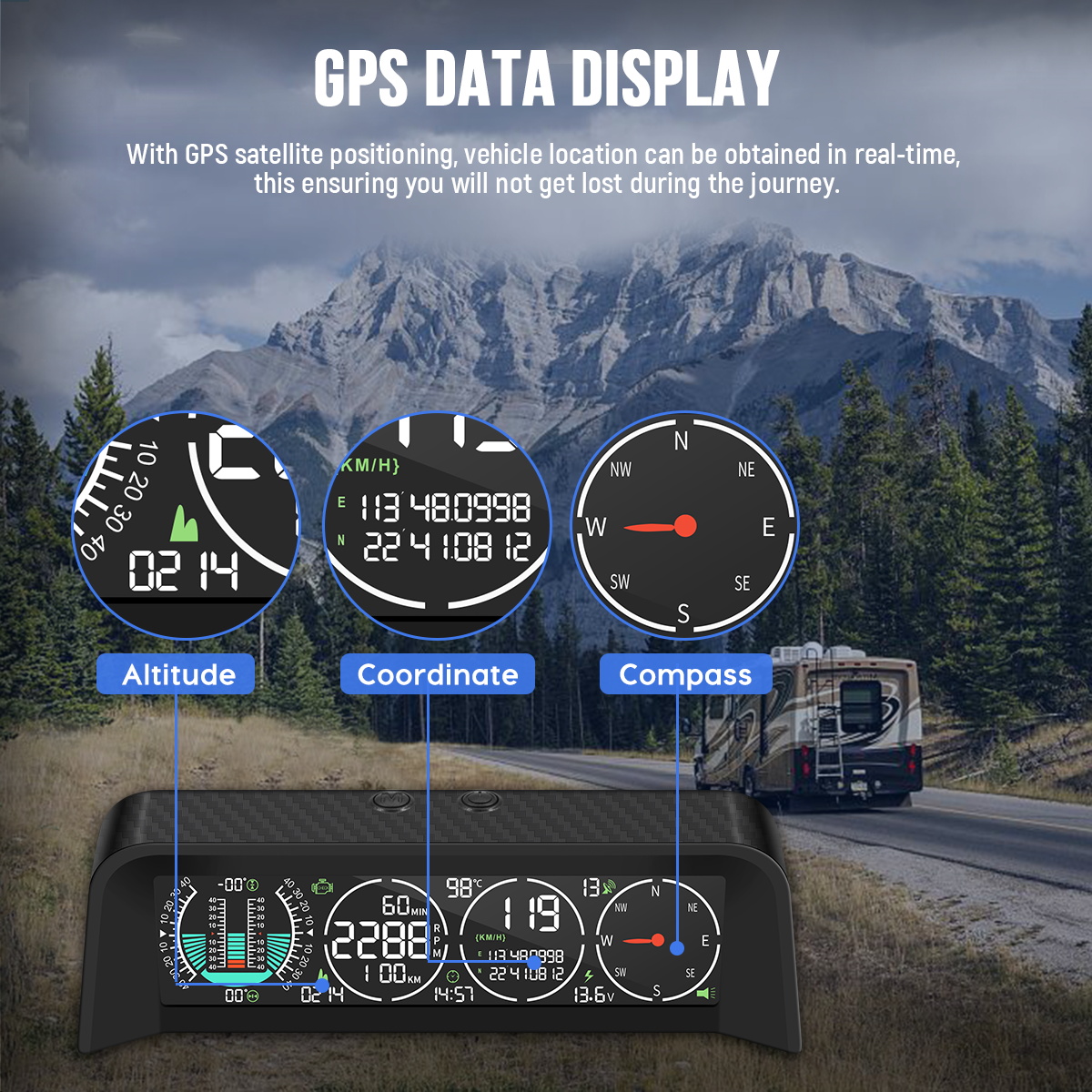
Altitude and coordinates are useful for orientation and trends but are not survey measurements. Compass direction may depend on vehicle motion and can be unstable while stopped. In tunnels, underground parking or urban canyons, expect satellite data to freeze, disappear or lag. Continue using required vehicle instruments and safe visual navigation.
Verify the live display
8. Compare vehicle and satellite speed carefully
On a safe open road, a qualified driver should hold a steady legal speed while a passenger records M80 and a trusted reference. Do not compare during acceleration, braking, a tight curve or GPS reacquisition because update rates differ. The exact page says driving speed synchronizes with car data; if the display offers a GPS/OBD choice, confirm the active source before evaluating an offset.
9. Interpret RPM, coolant, mileage and drive time
RPM should follow engine operating state without impossible jumps. Coolant should rise plausibly from ambient toward the vehicle’s controlled range; any suspected overtemperature requires the vehicle warning strategy and diagnostic procedure, not reliance on the accessory display. Driving time and mileage are trip information and can reset or differ from the odometer; do not use them as statutory maintenance or distance records unless separately validated.
10. Establish the angle reference
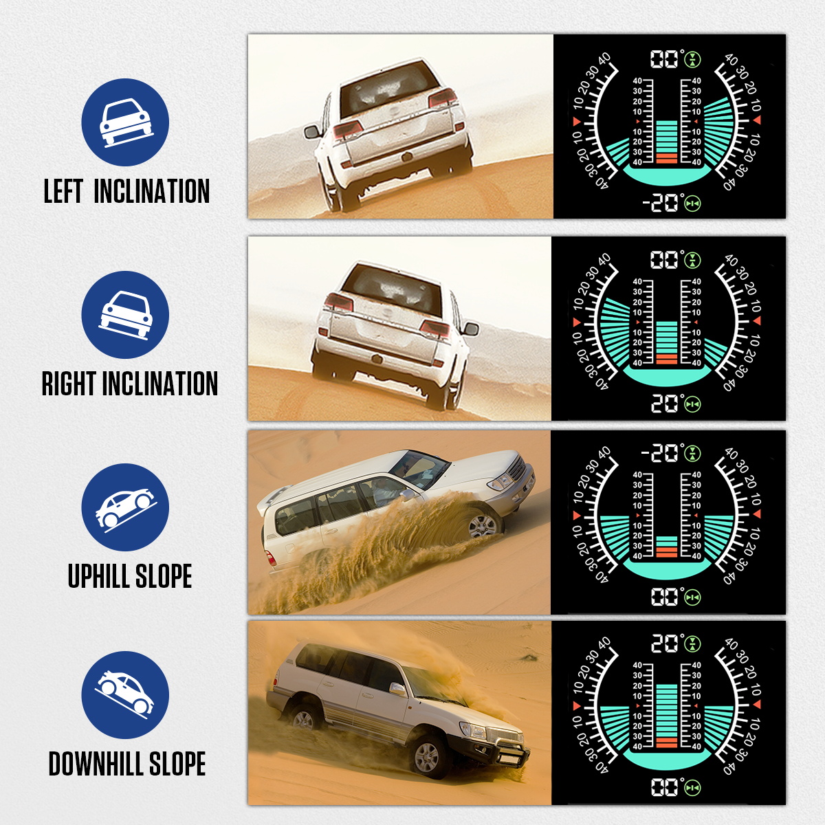
Use verified level ground with normal tire pressures, ride height and cargo. The page instructs horizontal adjustment but does not publish a button-calibration sequence, so do not borrow one from M50 or M60. Follow the printed manual and exact on-screen labels if a zero operation is exposed. Under a mild controlled condition, verify left/right and uphill/downhill directions, then return to the same baseline.
11. Treat voltage as a DLC trend
M80 sees voltage at its power pins. Connector contact, wiring and circuit load can create a difference from a calibrated battery-terminal measurement. Use the field to identify trends or gross changes. Diagnose a charging or starting fault with suitable equipment at the specified test points. Never conclude that the battery is healthy from one accessory voltage value.
Recheck the installation after the first drive
After a short controlled drive, park safely and repeat the stationary checks. Confirm that the adhesive base and bracket have not shifted, the case is still square with the vehicle centerline and the cable has not migrated toward pedals, steering parts or the driver’s knees. Review which fields stayed available: intermittent RPM or coolant points toward the OBD path, while a lost satellite count or direction points toward reception or mounting position. Switch the vehicle off and observe whether the display follows the expected sleep behavior after the vehicle’s normal shutdown period. Finally, return to verified level ground and compare the pitch and roll baseline with the value recorded immediately after installation. A changed baseline calls for mount inspection before any angle value is trusted. Record these observations together; they provide a much better starting point for diagnosis than changing several settings at once.
12. Use alarms as prompts
The listed roll, pitch and fatigue alarms are supplementary. The product page does not publish their exact thresholds or setting sequence. Do not test angle alarms by driving toward a rollover risk, and do not treat a fatigue timer as proof that a driver can continue. Stop safely when a warning appears or whenever road, vehicle or driver condition calls for it.
Troubleshoot by data source
| Symptom | Check first |
|---|---|
| No power | DLC supply, vehicle fuse, connector seating and DC 10–30 V compatibility |
| Power but no RPM/coolant | OBD-active icon, supported protocol, ignition state and DLC sharing |
| RPM works but no GPS fields | Open-sky position, satellite count and cold-start wait |
| GPS works but coolant blank | Vehicle may not expose the PID or OBD communication is incomplete |
| Speed values differ briefly | Active source, one-second GPS update and steady-speed comparison |
| Pitch and roll are mixed | Case rotation or bracket movement relative to the centerline |
| Voltage seems low | DLC contact and wiring drop; verify at specified electrical test point |
| Vehicle battery discharges | Constant DLC power, M80 sleep and network wake behavior |
Final M80 checklist
- Vehicle system voltage and OBD compatibility checked
- DLC and plug clean, undamaged and connected with ignition off
- Cable cannot contact pedals, steering, knees, airbags, heat or edges
- Display rigid, horizontal and square with vehicle centerline
- Road view, warnings, instruments, vents and light sensor unobstructed
- OBD-active icon and plausible RPM/coolant confirmed
- Open-sky GPS fix supported by time, satellites, coordinates and direction
- Actual key-off sleep and battery-drain behavior checked
- Speed source identified before comparison
- Pitch/roll directions verified without testing dangerous angles
- Voltage treated as DLC-path trend
- Alarms treated as prompts, not safe limits
- No calibration or hidden menu borrowed from another model
The M80 is a useful combined display when every number stays tied to its source. Install the DLC connection safely, mount the case square, verify OBD communication separately from satellite acquisition and evaluate angles separately from both. Required vehicle instruments, diagnostic procedures, terrain limits and driver judgment remain controlling whenever a field is missing, delayed or uncertain.











Comments 0
Questions, fixes, and real-world diagnostic notes from readers.
Be the first to share a diagnostic result or ask a follow-up question.