
How to Use the AUTOOL LM55 Digital Temperature Clamp

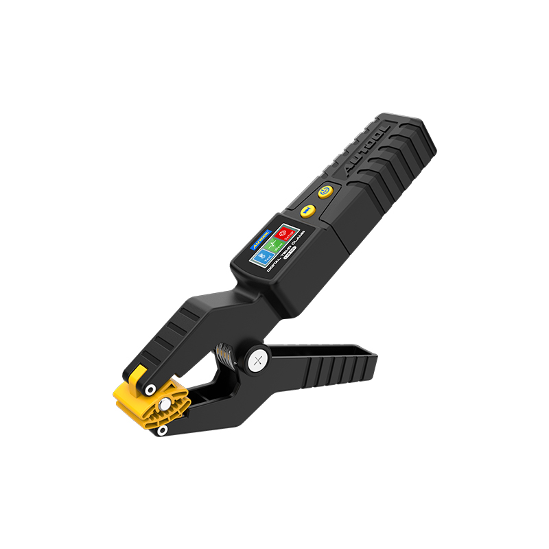
Use the AUTOOL LM55 by fitting three AAA batteries, selecting the temperature unit, clamping the sensor squarely onto a clean pipe smaller than 40 mm, and waiting for the reading to settle. Use Test for a live number or Wave to record the temperature trend. The reading is useful only when you also know which pipe you measured, the operating condition, and what the vehicle or HVAC procedure expects at that point.
The LM55 is a contact temperature clamp for HVAC, refrigeration, and automotive A/C pipes. It can show a live temperature, draw a 150-second temperature-versus-time trace, and retain eight waveform records. It does not identify refrigerant, measure system pressure, find a leak, or prove correct refrigerant charge by itself.
In this guide
What the LM55 measures
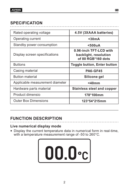
The AUTOOL LM55 measures the temperature at the pipe surface held between its clamp jaws. This direct contact makes it useful for observing suction-line and liquid-line temperature, comparing inlet and outlet points, checking how quickly a pipe responds after a system state changes, or collecting temperature data for superheat and subcooling calculations made with the correct pressure information.
The manual lists a measurement range of -50°C to 260°C and a maximum applicable pipe diameter below 40 mm. The current product instructions also tell users to avoid high-temperature test points and keep normal product-page testing below 150°C. Treat that lower instruction as the practical operating boundary: do not choose a dangerous surface merely because the display range extends higher. Use a correctly rated instrument and method when the specified test point is hotter.
Before you start
Open the AUTOOL manual download center and match the LM55 manual to the device in front of you. Then obtain the vehicle or equipment procedure that identifies the correct test points, operating state, stabilization time, expected temperatures, and any pressure measurements needed for interpretation.
Prepare three fresh AAA batteries, a clean lint-free cloth, a label or job sheet for naming each test point, and the pressure or scan data required by the diagnostic procedure. For under-hood automotive work, identify fans, belts, pulleys, exhaust parts, and any component that can move or heat unexpectedly.
Stop: Do not fit or reposition the clamp near a moving belt, pulley, fan, or hot exhaust surface. Switch the engine or equipment off before placing the clamp unless the approved procedure provides a safe remote placement method. Do not force the jaws onto a pipe 40 mm or larger, damaged tubing, a live electrical conductor, or a surface the clamp materials are not rated to contact.
Understand the two-button control
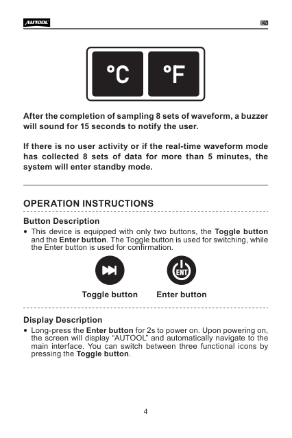
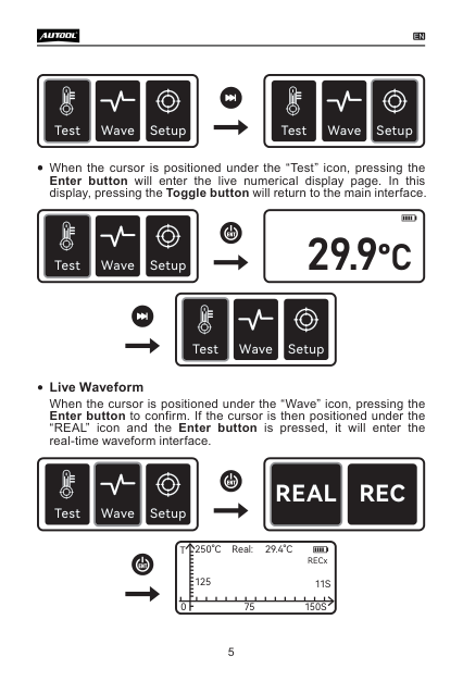
The LM55 has a Toggle button and an Enter button. Toggle moves between icons or choices. Enter opens or confirms the highlighted choice. Holding Enter for about two seconds powers the unit on.
The main screen has three areas:
- Test opens the live numerical temperature display;
- Wave opens the real-time trace or one of eight stored waveform records;
- Setup changes Celsius/Fahrenheit, screen brightness, and Chinese/English language.
Use the label shown on the delivered screen as the controlling reference. Do not memorize button presses from a different meter.
LM55 step-by-step operating procedure
Step 1: Define the measurement question
Write down exactly what you need to learn before touching the pipe. Examples include comparing two A/C lines under one stable operating condition, observing how one line warms after shutdown, or supplying a pipe temperature for a specified superheat or subcooling calculation.
Name each point by function and location, not only “hot” and “cold.” Record the required engine or equipment state, ambient condition, blower/load setting, pressure source, and stabilization rule from the applicable procedure.
Completion check: You know the exact pipe, exact location, operating state, and pass/fail method for the reading.
Step 2: Inspect the LM55 and the test point
Check the jaws, contact area, hinge, housing, buttons, display, and battery compartment. The jaws must close freely and hold the pipe without side load. Remove dirt from the contact surfaces without using a corrosive liquid.
Inspect the pipe for damage, oil, corrosion, heavy paint, insulation, moisture, and an irregular shape. Confirm its outside diameter is below 40 mm. Select a straight section that lets the jaws make stable contact and keeps the meter clear of heat and movement.
Stop: Replace or service the tool if the housing is cracked, the contact surface is damaged, the hinge is loose, the display is unreadable, or the clamp cannot remain secure.
Completion check: The tool is intact and the selected pipe section is safe, clean, accessible, and within the diameter limit.
Step 3: Install three AAA batteries
Keep the LM55 away from the pipe while opening the battery compartment. Install three 1.5 V AAA batteries with the polarity shown inside the compartment. Use a matched set; do not mix old and new cells or different chemistries.
Close the compartment fully before use. If the device will be stored for an extended period, remove the batteries to reduce leakage risk.
Completion check: The cover is secure and no battery or contact is loose.
Step 4: Power on and check the display
Hold Enter for about two seconds. The screen should show the AUTOOL startup display and then the main Test, Wave, and Setup icons.
Confirm that every needed part of the color display is visible. A missing segment, unstable startup, dim screen with fresh batteries, or unresponsive button can make a valid reading impossible to identify.
Completion check: The main screen appears normally and both buttons respond once per press.
Step 5: Set the unit, brightness, and language
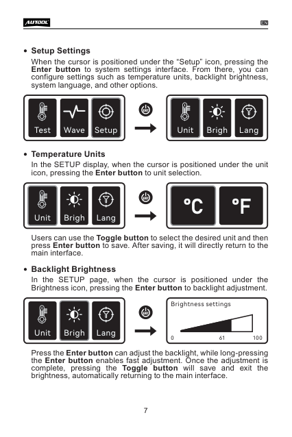
Use Toggle to highlight Setup, then press Enter. Select Unit, choose °C or °F with Toggle, and press Enter to save. Select Brightness, adjust it with Enter, and use a long press for faster adjustment; press Toggle to save and leave the brightness screen. Select Language, choose ENG if desired, and press Enter to save.
Use the same unit as the vehicle or equipment procedure. Converting halfway through a job creates avoidable transcription errors. Set only enough brightness for clear reading so the display does not distract you in a dark work area.
Completion check: Unit and language are correct, and the screen is readable from the safe observation position.
Step 6: Prepare the pipe surface
With the system stopped and safe to approach, wipe the selected contact area clean and dry. Remove only loose contamination. Do not grind, scrape, or damage a refrigerant line, and do not remove factory protection unless the service procedure permits it.
If insulation must be opened for an approved test, preserve it for correct restoration. Place a small location mark on adjacent safe material or record a photo so repeat measurements occur at the same point.
Completion check: The contact area is clean and the exact test location can be repeated.
Step 7: Clamp the sensor squarely onto the pipe
Open the jaws, center the pipe on the sensor contact area, and release the handles gradually. The jaws should sit square to the pipe and close under their own spring force. Do not twist the clamp to make it fit, wedge material into the jaws, or allow the tool’s weight to pull on a small tube.
Route the body so it cannot touch a belt, fan, exhaust part, electrical terminal, or another line. If the system must run for the test, place and secure the clamp while stopped, then move to the safe observation position before starting.
Completion check: The clamp is stable, the contact is repeatable, and the complete tool remains clear of heat, electricity, and movement.
Step 8: Read live temperature in Test mode
From the main screen, highlight Test and press Enter. The display shows the current pipe temperature. Do not record the first changing number as the result. The pipe, sensor, and clamp body need time to approach a stable contact condition.
Watch for a consistent trend and apply the stabilization rule from the equipment procedure. If the value jumps when you lightly support the tool, improve the contact and repeat the measurement.
Completion check: The reading has stabilized under the specified operating condition and does not depend on hand pressure.
Step 9: Record the complete operating condition
Write down the temperature with its unit, exact test-point name, date and time, ambient condition, engine or equipment state, blower/load setting, refrigerant-side pressure if required, and the stabilization period. A number without these conditions cannot be compared reliably later.
For automotive A/C diagnosis, do not decide “undercharged” or “overcharged” from one pipe temperature. Refrigerant identity, pressures, ambient and cabin load, airflow, compressor control, fan operation, and the vehicle test procedure all affect interpretation.
Completion check: Another technician could reproduce the same test from your record.
Step 10: Start a real-time waveform
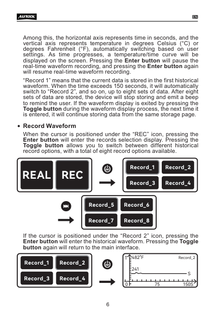
Return to the main screen with Toggle. Highlight Wave and press Enter, then select REAL and press Enter again. The horizontal axis represents time and the vertical axis represents temperature in the selected unit.
Keep the test condition steady unless the purpose is to record a controlled change. The LM55 stores 150 seconds in each record and advances through up to eight records. Use the graph to see direction, rate of change, oscillation, and stabilization—not to invent a pass limit that the service procedure does not provide.
Completion check: The waveform is moving, the test point remains secure, and the operating condition is documented.
Step 11: Pause or resume the trace when needed
Press Enter during real-time waveform recording to pause the trace. Press Enter again to resume. Pause only when the procedure needs a marker or when you must stop the equipment safely; repeated arbitrary pauses make timing comparisons harder.
The manual states that leaving the waveform display with Toggle does not erase the current storage position. When you return, recording continues from that record location until all eight records are filled.
Completion check: Any pause has a written reason and the resumed trace still represents the intended test.
Step 12: Review a stored waveform
Open Wave, select REC, and press Enter. Use Toggle to move through Record 1 to Record 8, then press Enter on the required record. Use Toggle again to return.
Match every reviewed record to the job sheet. The device names records by number, not by pipe or vehicle, so record the number at the moment of capture. After eight sets are stored, the LM55 stops storing and sounds a reminder for about 15 seconds.
Completion check: Each retained record is mapped to a known test point and condition; no old record is being mistaken for the current job.
Step 13: Compare points without changing the test
When the procedure requires two pipe temperatures, measure both at comparable locations and under the same stabilized operating condition. Reposition the clamp only with the equipment in a safe state. Clean the second point and repeat the full contact and stabilization checks.
Calculate a temperature difference only in the direction and units required by the procedure. Superheat and subcooling also require the correct refrigerant and its saturation temperature derived from a valid pressure reading at the specified side of the system. The LM55 alone does not supply those inputs.
Completion check: Both readings share the same operating condition and every additional input comes from the correct measurement or service data.
Step 14: Finish, clean, and store the clamp
Stop the equipment and wait until the area is safe before removing the LM55. Open the jaws with the handles; do not pull the sensor sideways off the pipe. Restore any insulation exactly as required, remove temporary marks where appropriate, and inspect the pipe for disturbance.
Wipe the tool dry with a soft cloth. Keep corrosive liquids away from the clamp, check for loose parts, and store it in a dry, ventilated place away from heat and humidity. Remove the batteries for extended storage.
Completion check: The test point is restored, the tool is dry and undamaged, and the result is attached to the correct job record.
How to judge a reliable LM55 reading
| Gate | Pass condition | Repeat or stop when |
|---|---|---|
| Contact | Jaws are square, stable, and fully seated on a clean pipe | Reading changes with hand pressure or contact shifts |
| Condition | System state, load, ambient condition, point, and time are known | The operating state changed without being recorded |
| Interpretation | The result is compared with the correct equipment procedure and supporting data | One temperature is being used as a complete A/C diagnosis |
Common LM55 problems
The reading changes too slowly
Confirm direct contact with a clean, straight pipe and allow enough stabilization time. Heavy coating, insulation, an oversized or irregular pipe, airflow over the clamp, or changing system operation can delay or distort the response.
The reading jumps when the tool moves
Stop the equipment before touching the clamp. Reposition it squarely and confirm the jaws close without side load. Do not hold the handles tighter to force a number; fix the contact instead.
Wave records are mixed up
Record the displayed record number beside the test-point name as soon as recording begins. After eight records, finish and document the set before starting another job rather than relying on memory.
The screen is hard to read
Check the three AAA batteries, then adjust brightness in Setup. If the screen remains incomplete or buttons respond intermittently, stop using the meter until it is repaired.
AUTOOL LM55 FAQ
Can the LM55 diagnose an automotive A/C system by itself?
No. It supplies contact pipe-temperature data. A complete diagnosis may also require correct refrigerant identification, high- and low-side pressures, ambient and vent temperatures, airflow checks, compressor/fan command data, leak inspection, and vehicle-specific service information.
What pipe size fits the clamp?
The manual specifies an applicable measurement diameter below 40 mm. Do not force the jaws over a larger pipe.
How long is each waveform record?
Each record spans 150 seconds, and the LM55 stores up to eight records before it stops storing and sounds a reminder.
What batteries does the LM55 use?
It uses three 1.5 V AAA batteries for a rated 4.5 V supply.
Can I use the full -50°C to 260°C display range on any surface?
No. The manual lists that measurement range, but the current product instructions say to avoid high-temperature test points and keep routine testing below 150°C. Surface safety, clamp material limits, access, and the equipment procedure control whether a point is suitable.
The reliable LM55 workflow
Define the test, inspect the tool and pipe, install three AAA batteries, set the correct unit, establish square contact, let Test mode stabilize, use Wave only under a controlled condition, map every record to its test point, interpret the result with the required pressure and service data, then remove and store the clamp safely. That sequence turns a temperature number into reproducible diagnostic evidence.











Comments 0
Questions, fixes, and real-world diagnostic notes from readers.
Be the first to share a diagnostic result or ask a follow-up question.