
How to Use the AUTOOL EM385: Programming Power, Charging, Display and Forced Start

The AUTOOL EM385 can support six different workshop jobs: hold vehicle voltage during an approved programming or diagnostic procedure, charge supported lead-acid or selected lithium batteries, provide controlled adjustable DC power, maintain power for a stationary vehicle display, attempt off-vehicle battery restoration, or support one suitable 12-volt starting attempt. It does not program an ECU, identify battery chemistry, choose a safe voltage, or prove that a battery is serviceable. Safe use begins by selecting the job first and verifying the vehicle, battery, load and mains conditions before output starts.
Use this guide with the manual supplied with your machine and the exact vehicle, battery or powered-equipment instructions for the job. The EM385 manual assigns operation to trained and qualified personnel. Vehicle preparation, programming voltage, terminal access, lithium-battery approval and the actual flashing or repair process must come from approved information for the equipment in front of you.
In this guide
- Choose the right EM385 mode first
- Before you connect anything
- Common setup and connection
- Use Programmable Power Supply mode
- Charge a supported battery
- Use Adjustable Power Supply only for a documented load
- Use Vehicle Display Mode
- Use Battery Restoration only off the vehicle
- Use Forced Start only after a suitability check
- Alerts, shutdown and storage
- Seven mistakes that cause most EM385 problems
- EM385 questions answered
- Final operating checklist
Choose the right EM385 mode first
| Your job | Select on the EM385 | Decision that must already be known | Critical limit |
|---|---|---|---|
| Hold vehicle voltage during diagnosis, coding or programming | Programmable Power Supply → Fixed Mode or Adjustable Mode | Exact vehicle or programming procedure; Fixed is 14 V, Adjustable is 9.0–16.0 V | EM385 supplies power only; it does not perform programming |
| Charge a supported installed lead-acid battery | Fast Charging → Lead-acid Charging → In-car Charging | Label identifies a permitted battery type and the vehicle allows in-place charging | Maximum described in-car current is 40 A; EFB is not an in-car choice |
| Charge a supported disconnected or removed lead-acid battery | Fast Charging → Lead-acid Charging → External Charging | Label, delivered manual and screen agree on chemistry | Maximum described external current is 20 A; EFB is external only when explicitly offered |
| Charge a supported lithium battery off the vehicle | Fast Charging → Lithium Battery Charging → LFP or NCM | Exact label identifies LFP or NCM and battery instructions permit this method | Maximum stated lithium charging current is 20 A/12 V |
| Power a known DC load | Fast Charging → Adjustable Power Supply | Required voltage, current, polarity and connection points are documented | 1–20 A at 3.0–8.9 V; 1–100 A at 9.0–16.0 V |
| Maintain power for a stationary vehicle display | Vehicle Display Mode | Vehicle procedure supplies the target within 9.0–16.0 V | Not a programming-mode substitute or unattended supply |
| Attempt recovery of a severely discharged supported battery | Battery Restoration | Battery is removed, physically safe and correctly identified | Conditional result; never an in-vehicle repair |
| Support one vehicle-start attempt | Forced Start | Exact vehicle procedure allows external support and demand is within the EM385 boundary | Treat 400 A/12 V as a transient ceiling, not guaranteed compatibility |
The nameplate on the delivered unit is the final authority for mains input. Regional input configurations exist. Do not infer universal 110/220-volt compatibility from an online specification, a manual table or another EM-series machine.
Before you connect anything
- Read the delivered manual and keep it in the work area. A current copy can also be located through the AUTOOL manual center.
- Identify one job before choosing a menu path. Programming Power, battery charging, Adjustable Power, Vehicle Display, Restoration and Forced Start are not interchangeable.
- Read the battery or equipment label. Record chemistry, nominal voltage, polarity, connection state and any manufacturer charging or support restrictions.
- Match the grounded outlet, input voltage and circuit protection to the EM385 nameplate. Never defeat protective earth.
- Work on a stable surface in a dry, clean, bright and well-ventilated area. Keep flames, sparks, conductive debris and corrosive material away.
- Wear eye protection and insulated gloves. Keep the unit away from the battery and leave both cooling fans unobstructed.
- Inspect the housing, mains lead, output cable, connector and clamps. Do not operate damaged equipment.
- Do not begin battery charging above 36°C ambient, and disconnect immediately if battery temperature exceeds 45°C.
- Follow the manual’s restriction for people with a pacemaker or other implanted cardiac device before approaching an energized machine.
Stop: Do not continue with a frozen, cracked, leaking, swollen, internally shorted or otherwise unsafe battery; uncertain polarity; damaged insulation; a mismatched supply; or any smoke, unusual odor, abnormal noise or excessive heat.
Common setup and connection
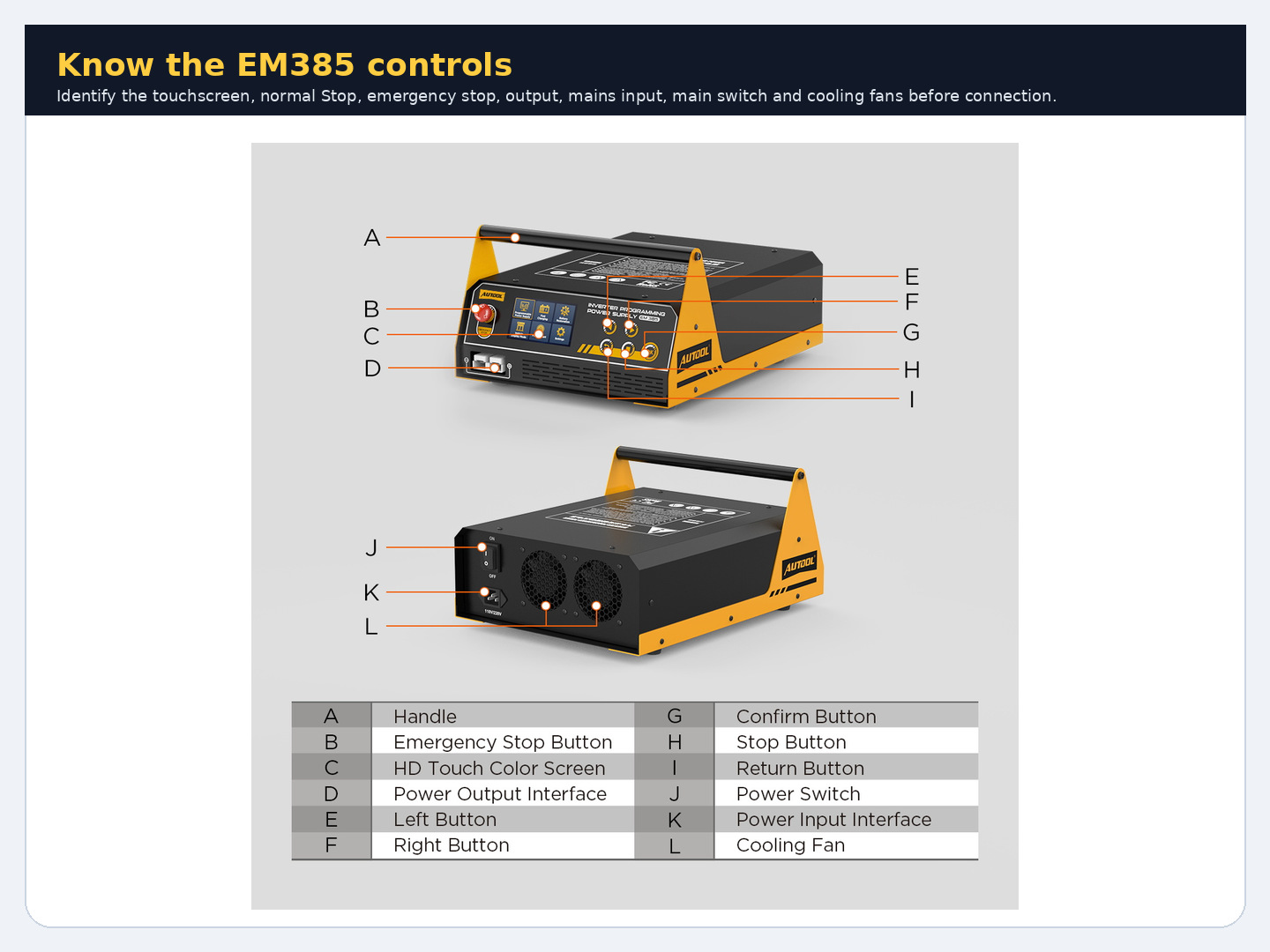
Step 1: Identify the controls and stop devices
On the front, locate the 4.3-inch touchscreen, output interface, Left, Right, OK, Stop and Return buttons, plus the red emergency-stop control. At the rear, locate the mains-input interface, main power switch and two cooling fans. The screen accepts touch input; Left and Right can move through choices, OK confirms, Return moves back, and Stop ends normal output.
Completion check: You can find normal Stop and emergency stop without searching, and both cooling fans have open airflow.
Step 2: Place the EM385 safely
Set the unit on a dry, stable surface and never directly on a battery. Keep at least the manual’s recommended 50 cm clearance from other objects where practical. Use the output-lead length to separate the machine from battery gases, and route both leads away from sharp edges, heat, belts, fans, tires and pinch points.
Completion check: The unit is stable, dry and separated from the battery, with clear ventilation and protected cable routes.
Step 3: Verify the delivered mains version
Read the input rating on the unit in front of you. Confirm that the outlet voltage, protective earth, plug and branch protection match it before inserting the mains lead. If the nameplate, plug or supply is unclear, pause the task and have the circuit checked.
Common mistake: Assuming every EM385 automatically accepts both 110 V and 220 V because both regional values appear in the manual.
Completion check: The delivered nameplate and actual grounded outlet have been matched without an adapter that interrupts protective earth.
Step 4: Identify the battery, vehicle or powered load
For a battery job, read the physical label rather than judging chemistry from case shape. Record whether it is Standard lead-acid, AGM flat plate, AGM spiral, GEL, EFB, LFP or NCM and whether it will remain installed, be disconnected or be removed. For programming, display or forced-start work, confirm the exact 12-volt vehicle procedure. For Adjustable Power, obtain the load’s required DC voltage, maximum current, polarity and approved connection points.
Stop: An unreadable or contradictory label, unknown system voltage, unsupported lithium chemistry or undocumented DC load means the task cannot begin.
Completion check: The physical item, documented requirement and intended EM385 mode all agree.
Step 5: Connect the supplied output cable with power off
Keep the rear switch off and leave mains disconnected. Seat the supplied output connector fully in the front interface. Arrange the red and black clamp leads so they cannot touch each other or bridge nearby metal. Do not substitute an undersized cable or modify the connector.
Completion check: The output connector is fully seated, cable insulation is intact and the two clamps remain separated.
Step 6: Attach the clamps with correct polarity
Use the exact vehicle, battery or powered-load procedure to locate positive and the approved negative connection point. Attach red to positive and black to the approved negative point. Keep your face away from a battery, avoid sparks near vents and confirm that neither clamp can rotate into adjacent metal.
Stop: Do not energize the machine if polarity, the negative point, terminal condition or clamp security is uncertain.
Completion check: Both clamps have clean, secure contact at documented points and the leads remain clear of moving parts.
Step 7: Power on and clear the initial screen
Connect the verified mains lead and switch on at the rear. Confirm that the touchscreen starts normally and that the emergency stop is released. Do not enter a work mode while Battery Not Connected, Reverse Polarity, Temperature Abnormality, Emergency Stop or a mains/output protection message is active.
Stop: Correct only the external condition identified by the warning guidance below. Never reset a warning simply to make the next screen appear.
Completion check: The display offers Programmable Power Supply, Fast Charging, Battery Restoration, Vehicle Display Mode, Forced Start and Settings with no active warning.
Use Programmable Power Supply mode
The AUTOOL EM385 holds vehicle voltage while a separate scan tool, computer and approved procedure perform diagnosis, coding or programming. The vehicle procedure controls the target voltage and every ECU action.
Step 8: Choose Fixed or Adjustable mode
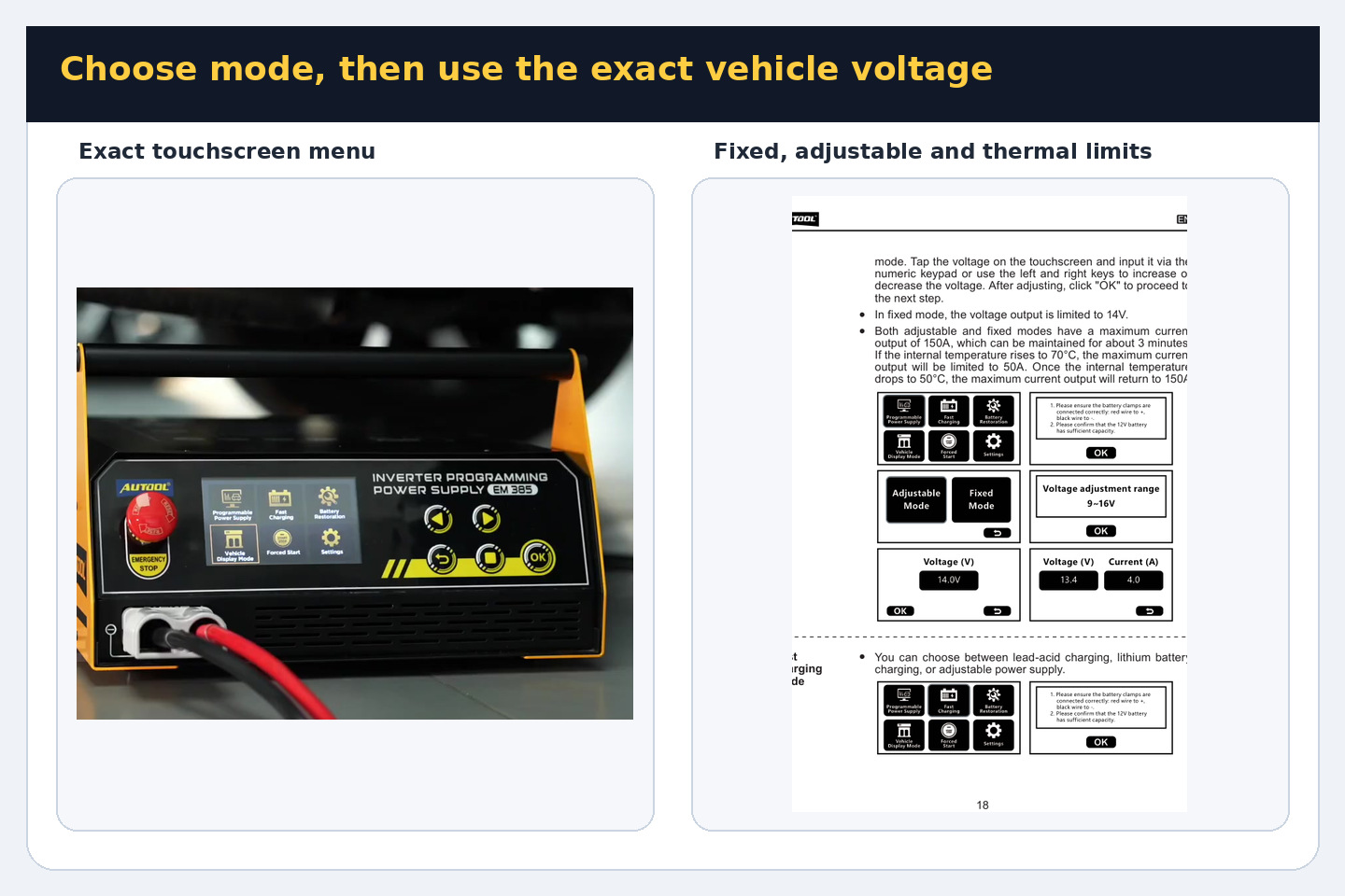
Touch Programmable Power Supply. Choose Fixed Mode only when the written procedure calls for the EM385 fixed 14-volt output. Choose Adjustable Mode when the procedure requires another target within 9.0–16.0 volts. Tap the voltage field and enter the value on the keypad, or use Left and Right, then confirm with OK.
Common mistake: Raising voltage because a higher number appears to offer stronger support. Voltage is a vehicle requirement, not a performance setting.
Completion check: The displayed mode and target voltage exactly match the approved vehicle procedure.
Step 9: Recheck battery charge and vehicle preparation
Read the on-screen connection prompt. Confirm correct polarity, stable terminals and a sufficiently charged vehicle battery before beginning. Complete every vehicle-side requirement for ignition state, doors, lighting, networks, cooling, accessories and charger connection before the separate diagnostic or programming process starts.
Stop: Do not begin with an incompletely prepared vehicle, moving clamp, uncertain voltage or unexplained load.
Completion check: The vehicle procedure is ready to start and every EM385 prompt can be confirmed from observed facts.
Step 10: Start support and monitor the entire session
Press OK to begin output. Watch EM385 voltage and current, the cables, battery temperature and the separate vehicle procedure continuously. The manual states a maximum programming output of 150 A for about three minutes. If internal temperature reaches 70°C, maximum output can be limited to 50 A; after cooling to 50°C, the higher ceiling can return. Plan from the vehicle’s measured demand rather than treating 150 A as unlimited continuous output.
Stop: End output if the vehicle procedure says to stop, voltage leaves the required range, an alert appears, the battery exceeds 45°C, or heat, odor, noise or smoke becomes abnormal.
Completion check: The separate diagnostic or programming process ends normally while the required voltage remains stable.
Charge a supported battery
Step 11: Choose the real battery location first
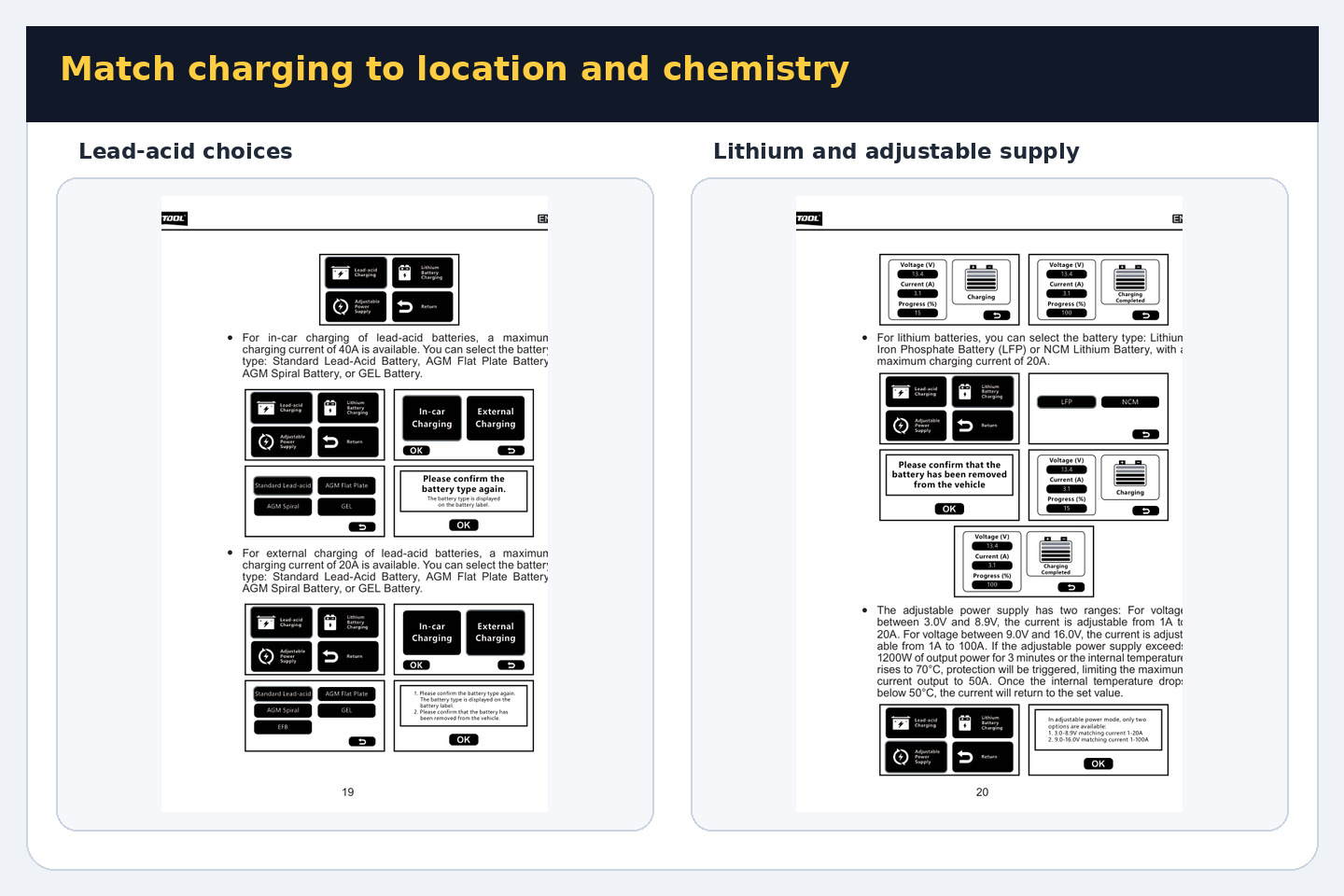
For a lead-acid battery, select Fast Charging → Lead-acid Charging, then select its actual connection state. In-car Charging is only for a supported installed battery when the vehicle procedure permits charging in place. External Charging is for a disconnected or removed battery. The operating pages describe up to 40 A in-car and up to 20 A external; those are mode ceilings, not a reason to choose the wrong location.
EFB is never an in-car choice. Use External Charging for an EFB only when the delivered manual and exact EM385 screen explicitly offer EFB there and the physical label confirms it. Otherwise use a charger approved for that exact battery.
Completion check: The selected location matches the battery’s real state, and EFB is never connected to the vehicle during an EM385 charge.
Step 12: Select and reconfirm the lead-acid type
Choose the chemistry printed on the battery label: Standard lead-acid, AGM flat plate, AGM spiral or GEL, plus EFB only under the external-only condition above. Press OK, then compare the confirmation screen with the label a second time. Similar case shapes do not make the types interchangeable.
Stop: A missing, contradictory or lithium label means the lead-acid charging path must not start.
Completion check: Screen, label, battery location and delivered-manual option identify the same supported type.
Step 13: Select LFP or NCM only off the vehicle
Disconnect and remove the battery as required by its manufacturer before using Fast Charging → Lithium Battery Charging. Choose LFP only for a label that explicitly identifies lithium iron phosphate, or NCM only for an identified nickel-cobalt-manganese battery. Confirm that the battery instructions permit external charging through these terminals and that its battery-management system is intact. The manual states a 20 A/12 V maximum for this path.
Stop: Do not charge an installed lithium battery, a different lithium chemistry, an undocumented pack, a damaged management system or any battery whose instructions require another charger.
Completion check: The isolated battery label, manufacturer charging method and selected LFP or NCM screen all agree.
Step 14: Monitor charging to a named end state
Start the selected charge cycle and remain present. Watch displayed voltage, current and progress as well as battery temperature, venting and case condition. Normal automatic completion is shown by Charging Completed. If you intentionally end earlier, press Stop and wait for output to cease before touching a clamp.
Stop: Stop for any warning, battery temperature above 45°C, leakage, swelling, abnormal gas or heat, unstable cable contact or an unsafe change around the work area.
Completion check: Charging Completed is displayed, or a deliberate Stop action has ended output before disconnection.
Use Adjustable Power Supply only for a documented load
Step 15: Define the adjustable-supply load before connection
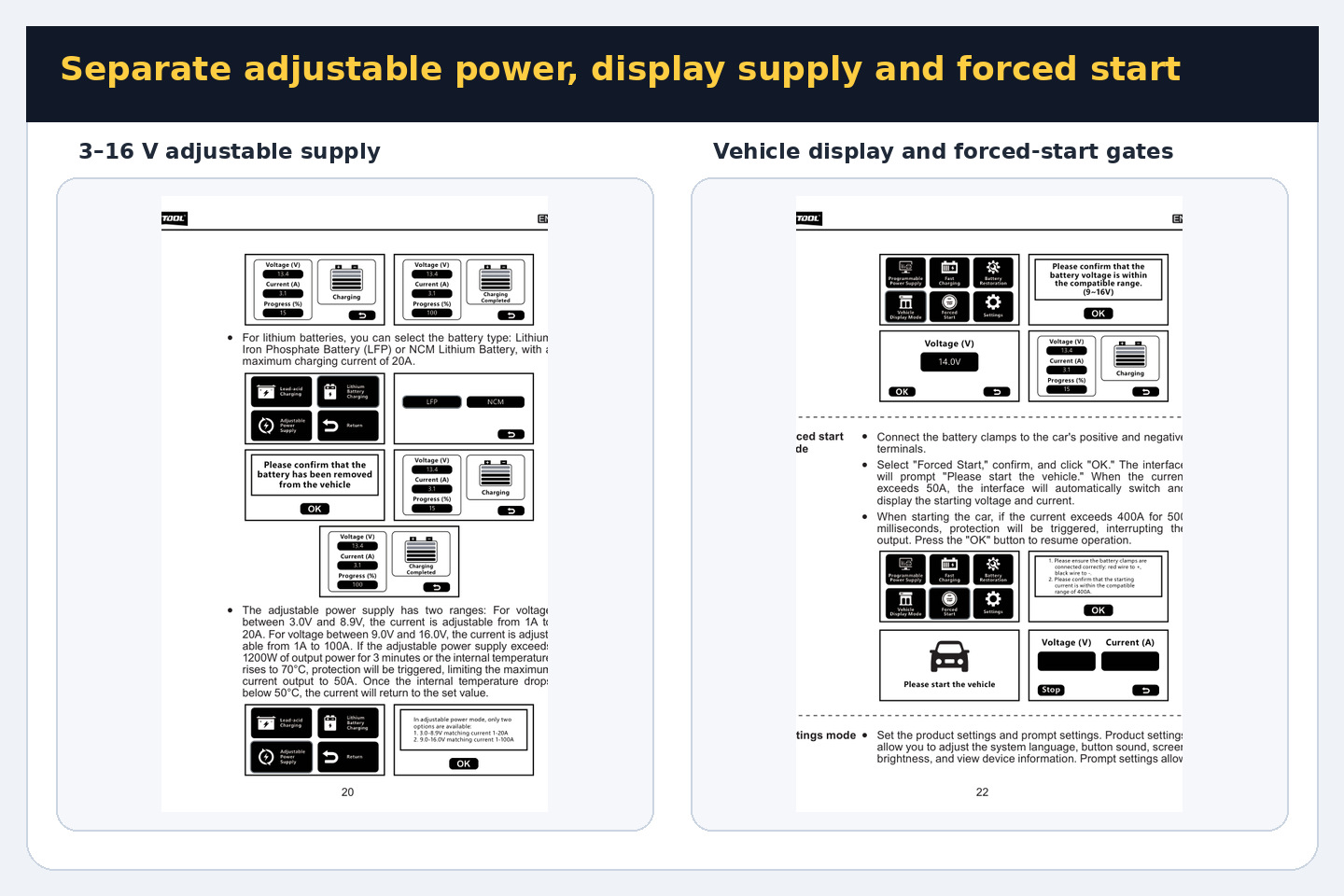
Obtain the equipment manufacturer’s required DC voltage, expected current, polarity, connection points and power-up sequence. The EM385 manual allows 1–20 A at 3.0–8.9 V and 1–100 A at 9.0–16.0 V. Those ranges describe the machine, not proof that an unknown component can accept the output.
Stop: Do not use Adjustable Power to discover an unknown component’s voltage, power an unsafe improvised circuit or bypass a required current-limited bench procedure.
Completion check: A written equipment specification defines voltage, current ceiling, polarity and connection sequence within one EM385 range.
Step 16: Enter voltage and current with output stopped
With output inactive, select Fast Charging → Adjustable Power Supply. Tap the voltage and current fields and enter values that do not exceed the documented load requirement or the applicable EM385 range. Recheck the decimal point, polarity and clamps before confirming. Incorrect selection can damage the connected equipment.
Common mistake: Setting the EM385 maximum because the load will supposedly draw only what it needs. The documented load limit still controls the setup.
Completion check: The screen, written requirement, selected range and physical polarity match exactly before output starts.
Step 17: Energize, observe and respect thermal reduction
Start output and monitor voltage, current, connection temperature and load behavior continuously. The manual says that operation above 1200 W for three minutes or an internal temperature of 70°C can reduce the maximum available current to 50 A. The set value may become available again after internal temperature falls below 50°C. Do not treat protection as extra working capacity.
Stop: Stop for current above the expected load, unstable voltage, warm or moving connections, any alert, or abnormal behavior from the powered equipment.
Completion check: The planned task finishes inside the equipment limit and EM385 range, then Stop ends output before any setting or lead changes.
Use Vehicle Display Mode
Step 18: Set display voltage from the vehicle procedure
Select Vehicle Display Mode and set the target within 9.0–16.0 V only after checking the vehicle procedure. The manual says EM385 applies a small float current during standby and can provide up to 40 A when vehicle discharge is detected. It also says a setting below battery voltage is automatically changed to battery voltage plus 2 V, so the displayed operating value must be checked before relying on it.
Common mistake: Treating Vehicle Display Mode as an unattended showroom supply or a convenient substitute for Programmable Power Supply.
Completion check: The target is permitted by the vehicle procedure and the displayed value remains acceptable after the machine’s automatic adjustment.
Step 19: Monitor the stationary vehicle load
Start display support and remain with the vehicle. Keep unnecessary loads off unless they are part of the planned display, watch voltage and current, and periodically inspect clamp position, leads and battery temperature. End the session before changing a setting or connection.
Stop: Stop for an alert, unplanned load increase, unstable voltage, cable movement, battery temperature above 45°C or any abnormal condition.
Completion check: The display session finishes with stable output and no warning, then normal Stop ends the mode.
Use Battery Restoration only off the vehicle
Step 20: Remove, identify and inspect the battery
Use the vehicle procedure to disconnect and remove the battery. Put it in an open, shaded and ventilated location, confirm that the delivered manual supports its chemistry, and inspect it again. Restoration is intended for some severely discharged batteries; the result depends on battery condition, and the process can cause fluid loss or internal drying.
Stop: Do not run restoration while connected to vehicle electronics, on an unsupported lithium battery, on an internally shorted battery or on a physically unsafe case.
Completion check: The battery is isolated, correctly identified, stable and safe to monitor for an extended cycle.
Step 21: Run restoration and interpret the result correctly
Reconnect the isolated battery using the common steps, select Battery Restoration, confirm the removal prompt and remain present. The manual describes three automatic results: Restoration Completed after 14.6 V is reached and float charging continues for two hours; Restoration Failed if a severely discharged battery does not rise to 9 V within one hour; or No Battery Restoration Required if initial voltage is above 12.6 V.
Common mistake: Repeating restoration until the screen passes, or treating Restoration Completed as proof of capacity and vehicle serviceability.
Completion check: A named end screen appears, output ends and the battery is separately tested before return to service.
Use Forced Start only after a suitability check
Step 22: Confirm that forced-start support is appropriate
Consult the vehicle procedure before connecting. Confirm a 12-volt system, approved external-support points and a starting-current requirement inside the EM385 boundary. Product information uses below 3.0 L as a broad qualifier, but engine size alone does not prove electrical compatibility. Use 400 A/12 V as a transient ceiling; do not rely on the higher end of any conflicting range.
Stop: Do not use Forced Start on an unknown-voltage system, unsafe battery, uncertain terminal arrangement or a vehicle whose procedure prohibits this support method.
Completion check: System voltage, terminals, battery condition and starter-current boundary are confirmed from exact vehicle information.
Step 23: Select Forced Start and read the prompt
With the common connection checks complete, select Forced Start and confirm. Recheck red-to-positive and black-to-approved-negative polarity, then press OK. The interface prompts you to start the vehicle. Keep the leads clear of moving parts and stand where the screen, clamps and vehicle can all be observed.
Stop: Do not continue if the prompt, voltage or connection state differs from the expected sequence.
Completion check: The machine shows the start prompt, both clamps remain secure and the vehicle is ready for one controlled attempt.
Step 24: Make one controlled start attempt and end support
Crank only as allowed by the vehicle procedure. When current exceeds 50 A, the screen changes to show starting voltage and current. The manual describes protection interruption around the 400 A boundary, including a 500-millisecond overcurrent condition. Resume only after the cause and vehicle suitability have been reassessed. Once the engine starts, end support and follow the vehicle procedure for safe disconnection.
Common mistake: Repeatedly resetting protection and cranking without diagnosing why the vehicle did not start.
Completion check: The vehicle starts within the approved attempt, or output is stopped and the no-start condition is diagnosed without repeated forced attempts.
Alerts, shutdown and storage
Step 25: Treat every alert as a stop-and-check gate
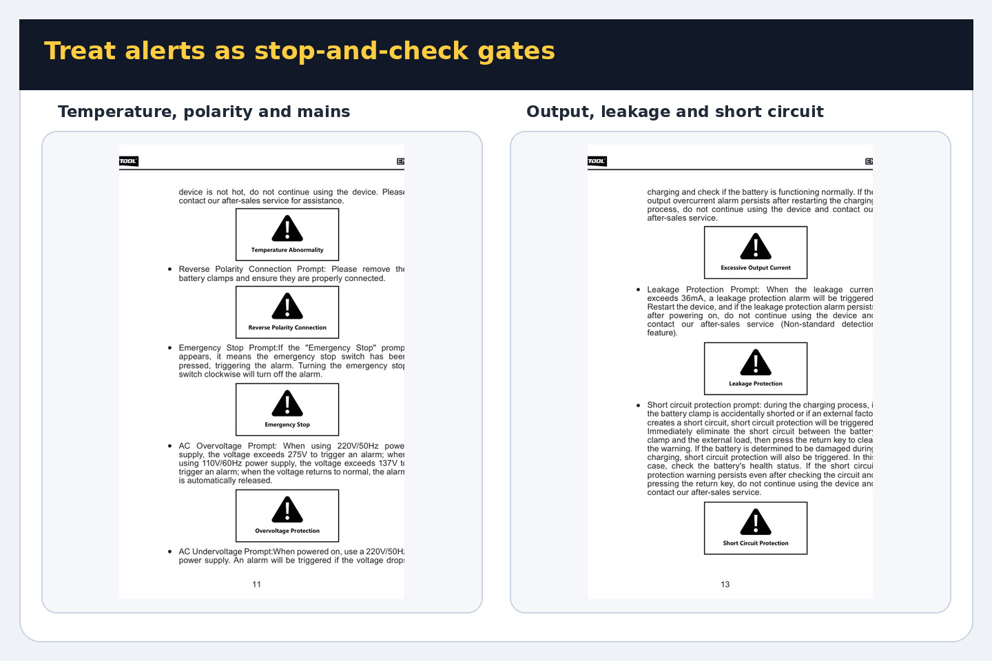
For Battery Not Connected, stop and inspect clean terminal contact before one careful reconnection. For Reverse Polarity, end output and remove the clamps before correcting polarity. For Temperature Abnormality, follow the manual’s cooling instruction and keep the fans running; do not continue if the warning appears immediately on a cold unit. Release Emergency Stop clockwise only after the reason it was pressed has been resolved.
AC overvoltage, undervoltage, input overcurrent, output overvoltage, output overcurrent, leakage and short-circuit warnings require the task to stop. Correct only an obvious external supply, battery, clamp, cable or load condition. Never open the case or bypass a protection state.
Stop: A persistent, unexplained or immediate cold-start warning keeps the EM385 out of service until qualified support checks it.
Completion check: The external cause is corrected and the screen returns normally, or the unit is isolated from service without bypassing protection.
Step 26: End the active function normally
Finish the separate vehicle or powered-equipment procedure first when applicable, press Stop on the EM385, and wait until the active-output screen ends. During charging, use the same Stop-first rule if the job is ending before automatic completion. Do not change mode, voltage, current, chemistry or connection while output is active.
Common mistake: Pulling the mains plug, pressing the emergency stop or removing a clamp to end routine operation.
Completion check: The display no longer shows active output and the mode has ended before any connection is moved.
Step 27: Disconnect, inspect and store
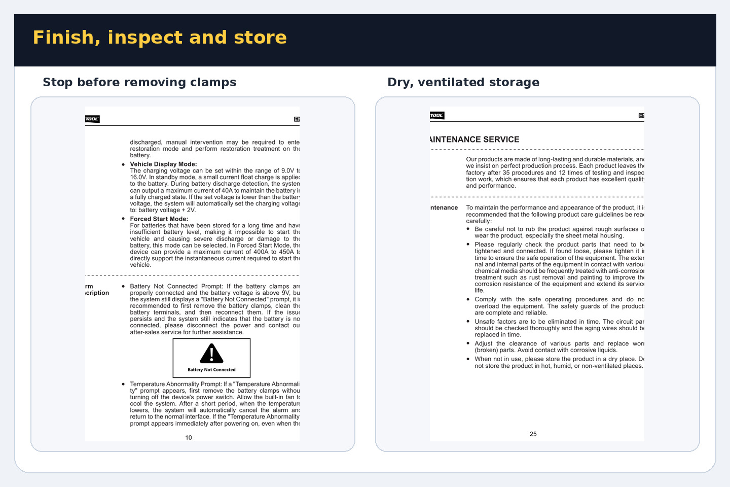
After output stops, remove the clamps in the order required by the vehicle, battery or equipment procedure, switch off at the rear and unplug mains. Inspect the housing, output connector, clamps and both leads. Coil the cables without sharp bends and store the EM385 dry, clean and ventilated, away from children, corrosive liquids, heat and humidity.
Stop: Do not store or reuse a unit with damaged insulation, a loose connector, impact damage or an unresolved heat, odor, noise or protection event.
Completion check: The machine is de-energized, disconnected, inspected and stored without cable strain or blocked ventilation.
Seven mistakes that cause most EM385 problems
- Treating the EM385 as the ECU programmer instead of a support supply.
- Guessing programming, adjustable or display voltage instead of using exact equipment information.
- Selecting battery chemistry by appearance or charging EFB in-car.
- Charging LFP or NCM while the battery remains installed, or selecting lithium chemistry from memory.
- Running restoration while the battery remains connected to the vehicle.
- Selecting Forced Start from engine size alone or repeatedly resetting protection after a no-start.
- Removing clamps or pulling mains before Stop has ended normal output.
EM385 questions answered
Can the EM385 charge a lithium battery?
Yes, but only in the dedicated lithium path for an identified LFP or NCM battery removed from the vehicle and approved for the method by its manufacturer. The manual gives a maximum of 20 A/12 V. A different lithium chemistry or unknown battery-management condition is not covered.
Can I charge an EFB battery while it remains in the car?
No. Current EM385 guidance makes EFB an external-only task. Proceed only if the battery is disconnected or removed and the delivered manual and screen explicitly offer EFB under External Charging. If they do not, use an EFB-approved charger.
Is 150 A continuously available in Programmable Power Supply mode?
No continuous 150 A promise should be assumed. The manual describes about three minutes at maximum programming output and temperature control that can reduce the ceiling to 50 A at 70°C until the unit cools to 50°C.
What is the difference between Adjustable Power and Vehicle Display Mode?
Adjustable Power is for a documented DC load and lets you choose both voltage and current within one of two ranges. Vehicle Display Mode is a vehicle-battery support path with its own automatic behavior and up-to-40 A description. Neither should replace Programmable Power Supply during an approved programming procedure.
Does the 400 A figure mean Forced Start works on every car below 3.0 L?
No. The figure is a transient ceiling, and displacement is only a broad product qualifier. Battery condition, system voltage, starter demand, terminal arrangement and exact vehicle instructions still decide whether support is appropriate.
Does Restoration Completed mean the battery is healthy?
No. It identifies the end of the EM385 cycle. It is not a capacity, conductance, load or vehicle-serviceability test. Evaluate the battery separately before reinstalling it.
What should I do if an alert returns after a connection check?
Stop using the unit. A persistent warning is not a request to open the case or keep resetting protection. Isolate the EM385 and obtain qualified support.
Final operating checklist
- Exact job, operating procedure and supported battery or load identified.
- Delivered nameplate matched to a grounded outlet and correct circuit protection.
- EM385 stable, dry, ventilated and separated from the battery.
- Cables, clamps, polarity and approved connection points checked.
- Correct mode, battery location, chemistry, voltage and current confirmed.
- LFP, NCM, EFB and Restoration kept inside their off-vehicle boundaries.
- Programming, Adjustable Power, Vehicle Display and Forced Start kept as separate workflows.
- Screen, current, voltage, temperature, leads and work area monitored throughout.
- Any warning treated as a stop-and-check condition.
- Stop used before clamps, settings or mains connection are changed.
- Battery condition, powered-load result or no-start cause verified separately before return to service.
The EM385 is easiest to use when each mode retains its own decision boundary. Let exact vehicle information control programming and display voltage, let the physical battery label and installation state control charging, give Adjustable Power only a documented load, reserve restoration for an isolated battery, and treat Forced Start as a carefully checked transient task. That method gives every job a clear start condition, completion check and safe stop point.











Comments 0
Questions, fixes, and real-world diagnostic notes from readers.
Be the first to share a diagnostic result or ask a follow-up question.