
How to Test Parasitic Battery Drain After Sleep Mode with AUTOOL BT960

If a battery goes flat after the vehicle sits, the useful number is not the current immediately after key-off. It is the stable current after the vehicle has completed its shutdown routine. The AUTOOL BT960 can bridge the battery-negative path, display that current and help you identify the branch that keeps consuming power.
Quick answer: prepare the vehicle so no door, key or timed load will wake it; wait for the model-specific sleep period; connect the BT960 red and black power clamps to the battery; zero Current mode; attach the yellow current lead to the removed negative cable; then watch for a stable reading. Compare it with the vehicle specification before pulling one fuse or disconnecting one branch at a time.
In this guide
What the BT960 is measuring
A parasitic-draw test measures current leaving the battery while the engine is off. That current is expected to be high for a short time because modules, lights and networks are still active. The diagnostic value appears after the vehicle reaches its documented sleep state and the reading stops stepping down.
| BT960 connection | Purpose in this test | Important limit |
|---|---|---|
| Red clamp | Battery positive; powers the tester | Use the exact polarity shown on the tool |
| Black clamp | Battery negative terminal | Keep firm contact on a clean conductive surface |
| Yellow current lead | Removed vehicle negative cable | Completes the measured path; do not start the engine or switch on a high load |
| Current mode | Displays and holds key-off current | The BT960 manual lists a 0–10 A measurement range |
This is different from the tester’s battery-health, cranking and charging tests. If those are your starting point, use the complete BT960 operating guide first, then return here for the sleep-mode current test.
Before you connect
- Verify that the battery is charged and serviceable. Low voltage can change module behavior and make the sleep pattern misleading.
- Find the vehicle’s permitted battery-disconnection method, normal sleep time and acceptable key-off current. Do not borrow a threshold from a different vehicle.
- Arrange hood, door and trunk latches so the vehicle can believe every opening is closed without trapping tools or cables.
- Keep the key, phone key and other transmitters far enough away that proximity functions do not wake the car.
- Identify alarm, telematics, retained-accessory-power and aftermarket circuits before testing.
- Do not crank, start or operate a high-current load while the BT960 is in the measurement path.
Some vehicles require memory support before battery disconnection. Use it only when the service procedure calls for it and account for the alternate current path it creates. If the vehicle cannot be safely placed in series without losing required initialization or exceeding the meter range, use an approved low-current clamp or the manufacturer’s specified method instead.
How to test sleep-mode battery drain with the BT960
Step 1: Establish a repeatable starting condition
Switch off the engine and accessories. Remove chargers that are not part of the test, close the vehicle and lock it in the normal way. Record the time. The official BT960 demonstration waits five minutes; that is a demonstration interval, not a universal sleep specification. Many vehicles require longer, and some modules wake periodically.
Step 2: Power the BT960 from the battery
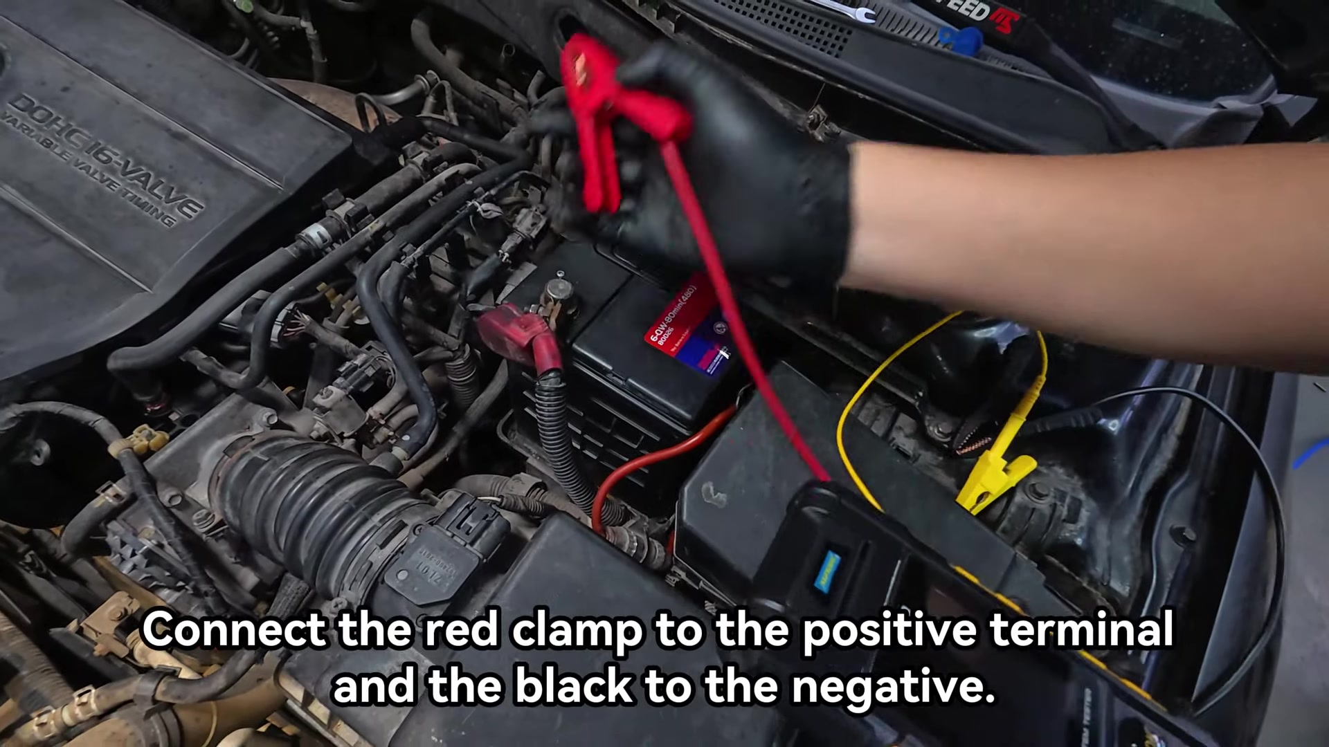
Connect the red tester clamp to battery positive and the black tester clamp to the battery’s negative terminal. Confirm that both clamps are secure and that the tester powers up normally. Route the leads so they cannot be pinched by the hood or pulled loose.
Step 3: Select Current mode and zero the reading
Open Current mode. With the yellow lead not yet carrying vehicle current, use the displayed long-press command to zero the measurement. A poor zero makes every later comparison uncertain, so repeat it if the screen does not settle at zero.
Step 4: Move the vehicle negative cable into the measured path
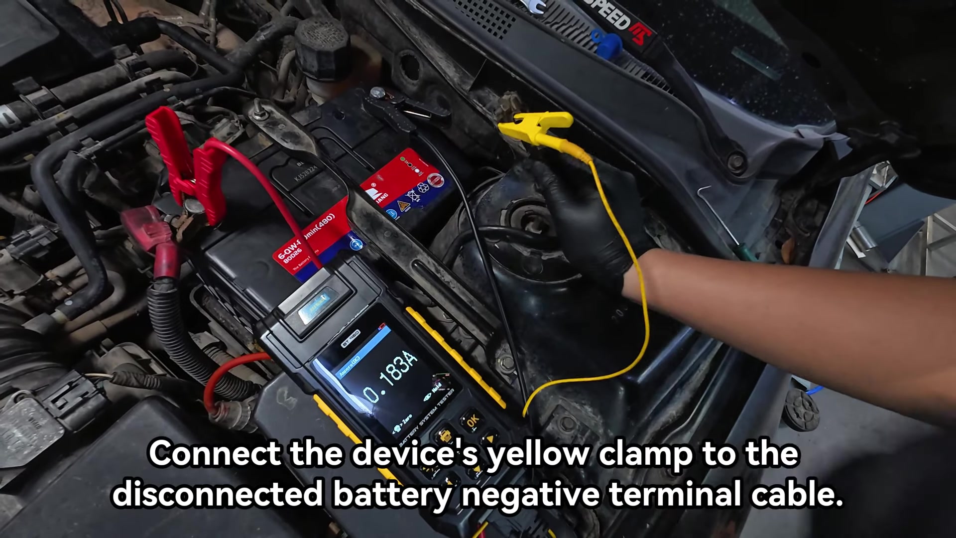
Following the vehicle’s battery-disconnection procedure, remove the vehicle negative cable from the battery post. Keep it from touching the post or body. Attach the BT960 yellow current lead to that disconnected cable. The tester now bridges battery negative to the vehicle ground side and displays the current passing through that path.
Step 5: Let the current settle without waking the vehicle
Watch the reading from a position that does not require opening a door or operating a key. A staged fall is normal as control units time out. Record the value and time at each plateau. If the tool approaches its rated range, stop safely and investigate the active load before continuing.
Step 6: Compare the stable value with the vehicle specification
The official video displays 0.050 A as its normal reference. Treat that number only as the video’s example. Vehicle architecture, alarm, telematics and sleep strategy determine the acceptable value. A stable result above the vehicle specification justifies circuit isolation; an unstable result first requires identifying what keeps waking the network.
Step 7: Isolate one branch without losing the baseline
Use the wiring diagram and fuse assignment, not random removal. Record the stable current, remove one permitted fuse or disconnect one controlled branch, then watch for a meaningful and repeatable drop. Reinstall it before moving to the next branch unless the diagnostic plan says otherwise. A fuse pull can wake modules, so allow the vehicle to sleep again before judging the new value.
Step 8: Confirm the cause and restore the battery connection
Once a branch changes the current, identify every device on that branch and test the suspected load directly. Do not call the fuse the fault. When finished, return the vehicle to a safe state, reconnect and tighten the negative cable to the vehicle specification, remove the tester leads and verify starting, charging, clock, windows, steering-angle or other required relearn functions.
Read the current pattern, not one snapshot
| Observed pattern | What it suggests | Next move |
|---|---|---|
| Current falls in several steps and stabilizes within specification | Normal timed shutdown is likely | Repeat under the complaint conditions if the battery still goes flat |
| Current remains high and steady after the specified sleep time | A continuous load may remain active | Use the diagram to isolate one branch at a time |
| Current repeatedly rises and falls | A module, network or proximity feature may be waking | Log the interval and correlate it with vehicle events |
| Reading changes when a lead is moved | The test connection is unreliable | Stop, clean and secure the connection before interpreting anything |
Stop the test if a clamp heats, a connection sparks repeatedly, the reading exceeds the tool range, the battery is damaged or hot, or the vehicle must be started. Restore the battery circuit using the vehicle procedure before changing the setup.
Common mistakes that invalidate the test
- Calling the first post-key-off number a parasitic draw before the vehicle sleeps.
- Opening a door, carrying the proximity key near the car or checking the dash during the test.
- Using 0.050 A as a universal limit instead of the vehicle specification.
- Pulling several fuses at once and losing the before-and-after comparison.
- Ignoring intermittent wake-ups because one later snapshot looked normal.
- Starting the engine or operating a high-current load through the current-measurement connection.
Frequently asked questions
Is a five-minute wait always long enough?
No. Five minutes is the interval shown in the official demonstration. Use the vehicle manufacturer’s sleep-time information and verify that the reading has reached a stable plateau.
Does a current drop after pulling a fuse prove the component is bad?
It identifies a branch that changed the load. The fault could be a module, relay, lamp, wiring path or a normal module that is being kept awake by another input. Continue with the wiring diagram and component-level checks.
Can I crank the engine while the yellow lead is connected?
No. The current-measurement path is for the controlled low-current key-off test, not starter current. Restore the normal battery connection before cranking or operating a large load.
BT960 parasitic-draw checklist
- Battery charged and safe to test
- Vehicle sleep time and acceptable current found
- Doors, latches and proximity keys controlled
- BT960 zeroed before current measurement
- Red and black clamps on the battery; yellow lead on the removed negative cable
- Stable value recorded with time
- Only one circuit change made at a time
- Negative cable restored and required relearns checked
The best result is not simply a low number. It is a repeatable sleep-state baseline, a controlled circuit change and a confirmed device or wiring cause.









Comments 0
Questions, fixes, and real-world diagnostic notes from readers.
Be the first to share a diagnostic result or ask a follow-up question.