
How to Choose and Connect FXTUL M3, M4 and M7 Motorcycle Diagnostic Cables

A motorcycle diagnostic cable is not chosen by connector shape alone. Start with a three-way match: the exact FXTUL scanner edition, the motorcycle’s documented diagnostic connector, and the current cable listing. This guide maps 16 current FXTUL M-series cable references and shows a controlled connection sequence for M3, M4 and M7 users.
Quick answer: Record the full scanner edition first, then identify the motorcycle’s exact year, model and diagnostic socket from its service information. Select the matching labeled FXTUL cable, inspect its keying and pins, make physical connections with the ignition off unless the vehicle procedure states otherwise, route the lead clear of heat and movement, then switch to the specified key state and verify communication. Never force a connector, bridge unknown pins or treat the same pin count as proof of compatibility.
In this guide
Match the scanner, motorcycle and cable before connection
“M3,” “M4” or “M7” is not always enough. M3 listings can distinguish A, B and C editions, while M4 listings can distinguish BMW, DUC, HD, EU and Asia editions. Write down the complete model shown on the device, case or purchase record before opening the cable selector.
- Scanner identity: record M3-A/B/C, the full M4 regional or brand edition, or M7.
- Motorcycle identity: record make, model, model year, engine and target control unit.
- Connector identity: locate it with exact vehicle service information and note its keying, latch and pin condition.
- Cable identity: use the printed cable label and current exact listing; do not identify a lead only by color or apparent pin count.
Current cable listings identify scanner-family associations, but they do not replace exact motorcycle coverage data. A listed BMW, Ducati, Kawasaki or Suzuki lead does not prove support for every motorcycle year, ECU or service function under that brand.
FXTUL M3, M4 and M7 cable selector
| Current cable listing | Scanner editions named by the listing | Required final check |
|---|---|---|
| BMW 10-pin | M4-BMW / M7 | Confirm exact motorcycle/year coverage before ordering or connecting. |
| Benelli 6-pin | M4-Asia / M7 | Confirm exact motorcycle/year coverage before ordering or connecting. |
| Ducati 4-pin | M4-DUC / M7 | Confirm exact motorcycle/year coverage before ordering or connecting. |
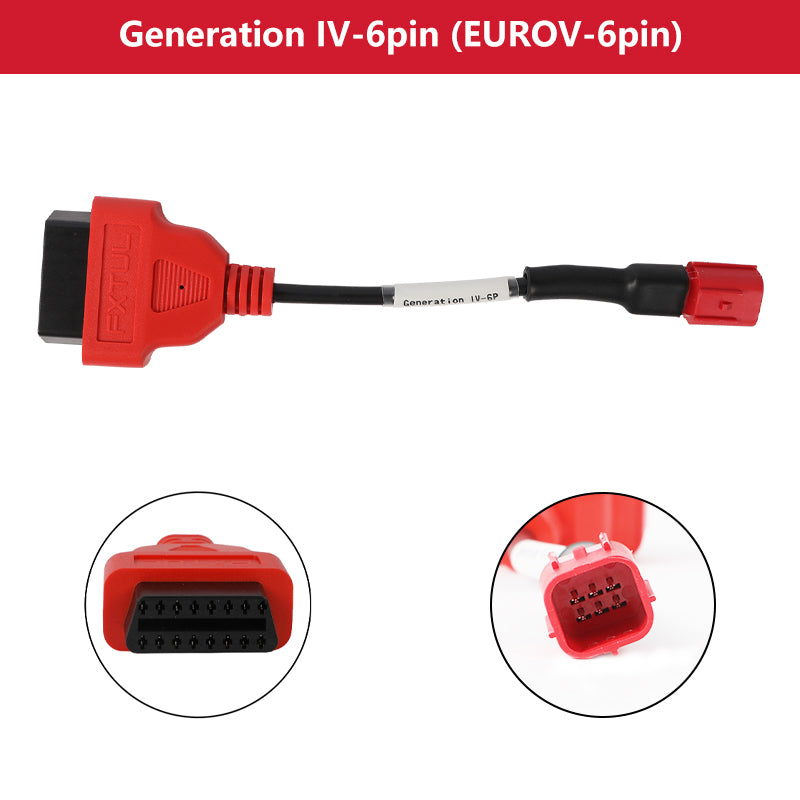
| Generation IV / EuroV 6-pin | M3-A/B/C; M4-BMW/DUC/HD/EU/Asia; M7 | Confirm exact motorcycle/year coverage before ordering or connecting. |
| Harley 4-pin / 6-pin | M4-HD / M7 | Confirm exact motorcycle/year coverage before ordering or connecting. |
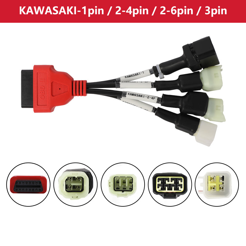
| Kawasaki group: 1-pin / 2–4-pin / 2–6-pin / 3-pin | M3-A / M4-EU / M4-Asia / M7 | Confirm exact motorcycle/year coverage before ordering or connecting. |
| Kawasaki group: 4–6-pin / 5–4-pin / 6–4-pin | M3-A / M4-EU / M4-Asia / M7 | Confirm exact motorcycle/year coverage before ordering or connecting. |
| KTM 6-pin | M4-Asia / M4-EU / M7 | Confirm exact motorcycle/year coverage before ordering or connecting. |
| M3 OBD2 / Euro5 6-pin universal | M3 | Confirm exact motorcycle/year coverage before ordering or connecting. |
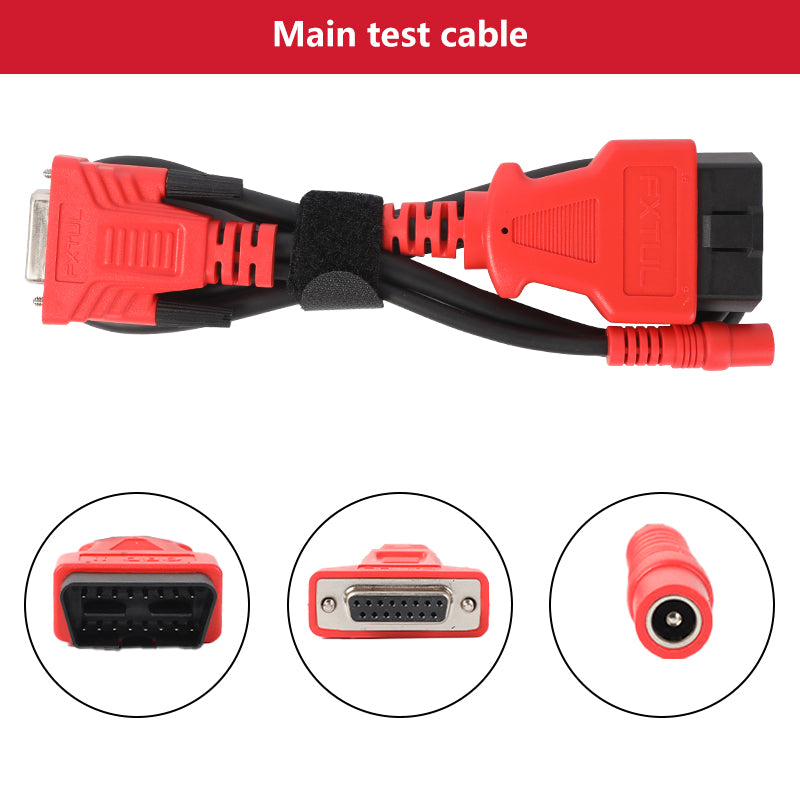
| M7 main test cable | M7 | Confirm exact motorcycle/year coverage before ordering or connecting. |
| PGO 6-pin | M4-Asia / M7 | Confirm exact motorcycle/year coverage before ordering or connecting. |
| Polaris 8-pin | M7 | Confirm exact motorcycle/year coverage before ordering or connecting. |
| Suzuki-2 | M3-A/B/C; M4-BMW/DUC/HD/EU/Asia; M7 | Confirm exact motorcycle/year coverage before ordering or connecting. |
| Suzuki 4-pin / 6-pin | M3-C / M4-EU / M4-Asia / M7 | Confirm exact motorcycle/year coverage before ordering or connecting. |
| Universal K-Line | M3-A/B/C; M4-BMW/DUC/HD/EU/Asia; M7 | Confirm exact motorcycle/year coverage before ordering or connecting. |
| Vespa 3-pin | M3-C / M4-Asia / M4-EU / M7 | Confirm exact motorcycle/year coverage before ordering or connecting. |
The two Kawasaki groups are intentionally separate because the current listings contain different connector sets. Likewise, “Generation IV / EuroV 6-pin” and the separately listed “M3 OBD2 / Euro5 6-pin universal” cable should not be treated as interchangeable merely because both descriptions mention Euro5. Match the exact listing, scanner edition and motorcycle procedure.
How to connect an FXTUL M-series motorcycle diagnostic cable
Step 1: Record the complete scanner edition
Read the device, case and purchase record before choosing a lead. Record M3-A, M3-B or M3-C where applicable; record the complete M4-BMW, M4-DUC, M4-HD, M4-EU or M4-Asia edition; or record M7. Keep mixed cable kits separated until each lead is identified by its label.
Check: The job record contains the complete scanner edition, not only the family name.
Step 2: Identify the exact motorcycle and target system
Record make, model, model year, engine and the control unit you intend to scan. Confirm current tool coverage for that exact combination and function. Brand-level coverage is not enough: engine communication does not automatically prove ABS, instrument, immobilizer or service-function coverage.
Check: The exact motorcycle and intended ECU/function have a supported diagnostic route.
Step 3: Locate the documented diagnostic connector
Use exact motorcycle service information to locate the diagnostic socket and determine which cover or seat must be removed. Inspect the housing key, latch and pin condition without probing unknown terminals. Stabilize the motorcycle before working under a seat or near a side panel.
Check: The documented socket is accessible, undamaged and positively identified.
Step 4: Select the exact labeled cable
Use the selector above to narrow the current listing, then confirm the cable’s printed label and full scanner-edition association. Treat the two Kawasaki sets, the separate Euro5-related listings and all M4 editions as distinct until the exact listing and vehicle information prove the required lead.
Check: Scanner edition, motorcycle connector and labeled cable agree.
Step 5: Inspect the complete connection chain
Check connector housings, keys, latches, terminal alignment, strain relief and insulation. Keep the lead out of service if a terminal is bent, recessed, spread, corroded or wet, if a latch is broken, or if insulation or strain relief is damaged. On M7, inspect the main test cable and vehicle adapter as separate items.
Check: Every part of the intended chain is clean, dry, intact and correctly identified.
Step 6: Set a controlled ignition and power state
Follow the motorcycle service procedure for key position and any external power requirement. Unless that exact procedure directs otherwise, keep the ignition off while making or moving physical connectors. Stabilize vehicle and scanner power before beginning a session; do not connect a charger or auxiliary supply with uncertain mode or polarity.
Check: The motorcycle and tool are in the documented pre-connection state with stable power.
Step 7: Build and seat the cable chain without force
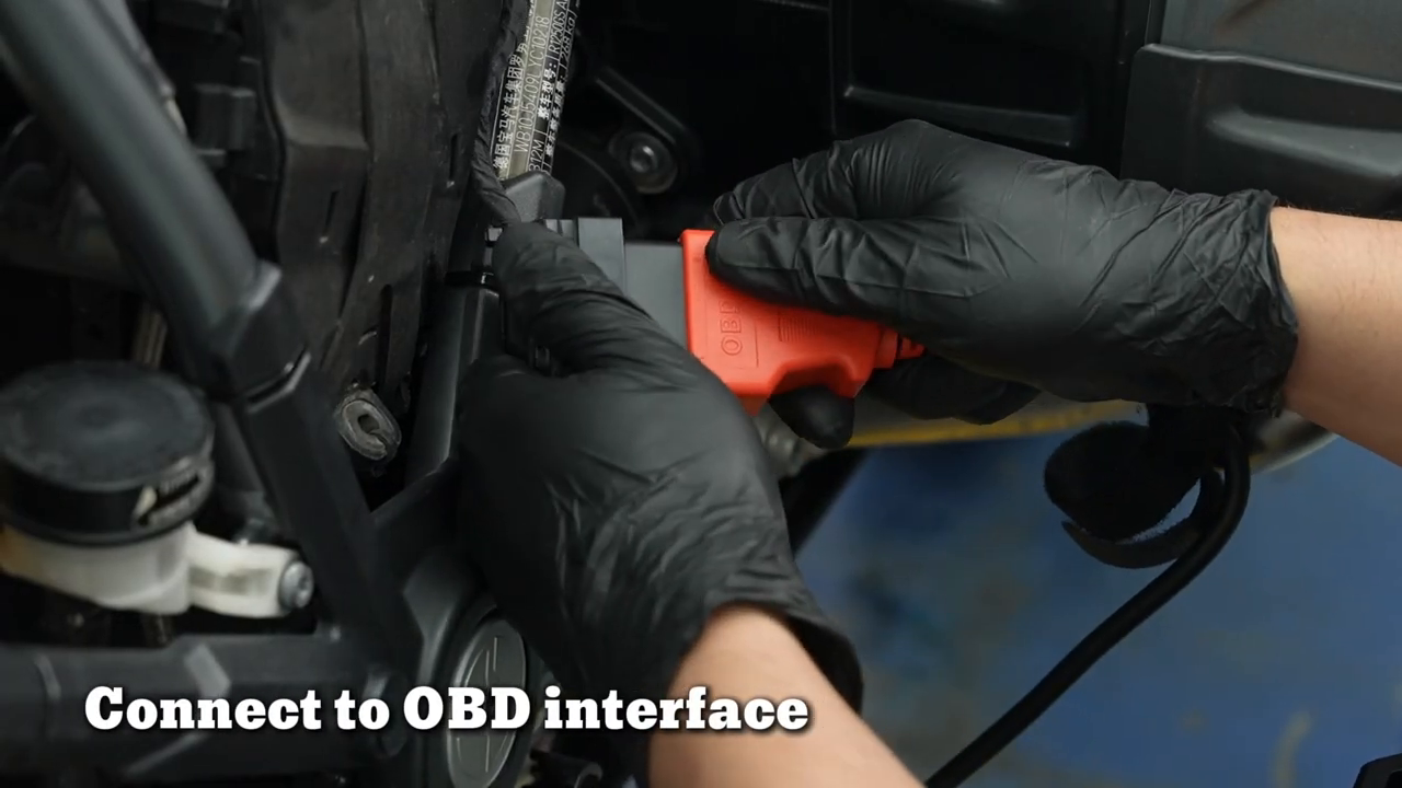
Join the scanner-side lead and exact vehicle adapter using their keyed housings, then align the adapter with the documented motorcycle socket. Push on the housings—not the wire—until the intended latch or seating point is reached. Stop immediately if keying, depth or latch engagement is uncertain.
Check: All junctions are fully seated by hand with no pin displacement, improvised keying or harness load.
Step 8: Route the lead clear of heat and movement
Provide slack for normal steering and access without letting the cable touch exhaust components, cooling fans, the chain, wheels, belts or sharp panel edges. Do not close a seat or cover on the lead. Support the scanner so its weight cannot pull on the motorcycle harness.
Check: The complete lead remains visible, strain-free and outside every hot or moving zone.
Step 9: Enter the specified key state and start diagnosis
Move the ignition or run/stop switch only to the state required by the exact diagnostic procedure. Select the correct brand, vehicle and system route on the scanner. Confirm that the displayed vehicle or module identity matches the job before accepting any command that can clear data or change state.
Check: The scanner communicates with the intended ECU and the displayed identity matches the motorcycle.
Step 10: Save the baseline before changing anything
Record the initial system status, DTC numbers and states, module identity, freeze data and only the live parameters needed for the diagnostic question. Do not use clear, reset, actuation or calibration as a connection test. A successful connection is not proof that a stored fault identifies the failed part.
Check: A readable before-state exists and no evidence has been erased merely to test the cable.
Step 11: Exit, power down and disconnect by the housings
Exit the diagnostic session normally, return the ignition to the state required for disconnection and switch it off unless the exact procedure states otherwise. Remove the motorcycle-side adapter by its housing, then separate intermediate and scanner-side junctions. Refit protective caps and vehicle panels only after checking for pushed-back pins or trapped wiring.
Check: The motorcycle harness is restored, all pins remain aligned and the labeled cable is stored without tight bends or contamination.
What to check when the scanner will not communicate
No communication is a diagnostic result, not permission to try random adapters. Return the motorcycle and tool to a controlled state, then check the chain from identity to power and physical connection.
- Confirm the complete scanner edition and current software coverage for the exact motorcycle and target ECU.
- Confirm the selected cable listing names that scanner edition and that the cable’s physical label matches the job record.
- Recheck connector location, key state, latch engagement, terminal condition and vehicle battery voltage against exact service information.
- Inspect the main lead and every adapter junction; an M7 main test cable and a vehicle-specific adapter are separate parts of the chain where applicable.
- Exit diagnosis normally before moving a connector. Never bridge pins, back-feed a terminal or re-key a housing to obtain communication.
Stop: Disconnect and investigate before continuing if a connector will not seat by hand, a pin is bent or pushed back, a lead becomes hot, the harness is pulled tight, polarity is uncertain, voltage is unstable, or the motorcycle service information does not identify the socket. Do not use a nearby connector as a substitute.
Common cable-selection mistakes
- Choosing by pin count or connector color instead of the complete cable label and exact vehicle procedure.
- Treating all M3 or all M4 editions as identical when a listing names only particular editions.
- Combining the two Kawasaki connector groups or treating separate Euro5 listings as one universal lead.
- Connecting with the harness under tension or leaving the cable near the exhaust, fan, chain, wheel or steering path.
- Clearing faults before saving the baseline scan and confirming why communication or a DTC changed.
- Pulling on the wire instead of the connector housing during disconnection.
Frequently asked questions
Can I choose a motorcycle diagnostic cable by pin count?
No. Pin count alone does not prove keying, pin assignment, protocol, scanner-edition support or motorcycle coverage. Use the exact cable label, current listing and vehicle service information.
Does an M7 use the same cable for every motorcycle?
No. The current catalog includes an M7 main test cable plus multiple vehicle-specific adapter listings. Build only the chain identified for the exact motorcycle and supported diagnostic route.
Are all M4 versions compatible with the same cable set?
No. Current listings distinguish M4-BMW, M4-DUC, M4-HD, M4-EU and M4-Asia. Use the complete edition name rather than the M4 family name alone.
What should I do before clearing a fault code?
Save the initial scan, module identity, DTC state and useful freeze or live data first. Clearing a code is not a repair and can erase evidence needed to find the cause.
Final cable connection checklist
- Complete scanner edition and current software coverage confirmed
- Exact motorcycle, target ECU and documented diagnostic socket confirmed
- Printed cable label matches the current listing and scanner edition
- Pins, keying, latch, housings and lead insulation clean and undamaged
- Ignition/key state follows exact service information
- Every connector fully seated by hand with strain relief and safe routing
- Communication and vehicle identity verified before any state-changing command
- Baseline evidence saved; session exited; ignition off and connectors removed by their housings
The fastest reliable workflow is to slow down before connection: identify the complete scanner edition, confirm the motorcycle socket and choose the exact labeled cable. Once those three facts agree, connection, communication checking and disconnection become repeatable instead of trial and error.











Comments 0
Questions, fixes, and real-world diagnostic notes from readers.
Be the first to share a diagnostic result or ask a follow-up question.