
Electronic Parking Brake Will Not Release? Prove Power, Command, Motor, and Mechanics Before Forcing It

Release Only After Proof
An electronic parking brake that will not release is both a diagnostic problem and a vehicle-control hazard. The first objective is not to make the actuator move. It is to prevent the vehicle from rolling, protect anyone near the brakes, and determine whether the system is refusing a command or physically unable to release.
A direct motor-release tool is a narrow recovery option only after the actuator circuit and direction are identified. The AUTOOL BT10 EPB release tool is one route for trained use, not a code reader, service-mode substitute, calibration device, or permanent repair.
Work through four gates: power, command, actuator, and mechanics. Each gate must supply evidence before the next is forced. A low battery, missing brake-pedal input, damaged switch circuit, seized caliper, and failed motor can all produce the same immobile vehicle. Incorrect polarity or uncontrolled motion can cause damage or injury.
Quick answer: Secure the vehicle, then prove four gates in order: usable power, a valid release command, actuator circuit response, and free brake mechanics. Use only the exact emergency or direct-release method after the design is identified.

In this guide
- Secure the vehicle before gate one
- Gate one: prove usable power
- Gate two: prove the release command
- Gate three: evaluate actuator response
- Gate four: separate motor from mechanics
- Decide whether temporary direct release is justified
- What not to do with an immobilized EPB
- Verify normal apply, hold, and release
Secure the vehicle before gate one
Place the vehicle on a stable surface. Use wheel chocks appropriate for its weight and slope, select Park or a gear as applicable, and support the vehicle correctly if any wheel will be lifted. Do not rely on the failed parking brake to hold it. Keep people clear of the travel path.
Read the owner and service information for towing, emergency release, brake service, and power-loss procedures. Some systems act on rear calipers; others use cables, drum-in-hat mechanisms, or centralized actuators. The release method and risk change with the design.
Assume an electric motor or cable can move unexpectedly whenever power, a scan command, or direct voltage is applied. Keep hands and tools away from pinch points. If the vehicle cannot be secured or the system cannot be positively identified, recovery belongs with properly equipped service personnel.
Gate one: prove usable power
Measure battery condition at the posts and observe voltage during a release request. An illuminated dashboard does not prove the battery can support motor current. Charge and test the battery as required, then inspect relevant fuses, main feeds, grounds, and connections.
Record low-voltage, communication, ABS, stability-control, and parking-brake codes before clearing anything. A battery event may leave useful history. If several modules report undervoltage, stabilize system power before interpreting downstream actuator faults.
Voltage at an unplugged connector is not enough. A corroded feed or ground may show battery voltage with no load and collapse when the motor is commanded. Use voltage-drop or other loaded circuit tests following the wiring diagram and safe back-probing practice.
Gate two: prove the release command
Many vehicles require ignition state, brake-pedal input, gear position, door or seat-belt conditions, and a valid switch request before release. Watch these inputs in live data if available. A failed brake-light switch can block release even though the parking-brake motor is healthy.
Check the console switch physically and electrically. Does the module see “apply” and “release”? Are there implausible or stuck states? Inspect recent console, trim, battery, brake, or body work that may have disturbed the circuit.
Read the exact fault status and freeze data. If the controller receives all prerequisites and issues a release command, the boundary moves toward the actuator circuit and mechanics. If it never commands release, resolve the missing input, configuration, communication, or module condition first.
Gate three: evaluate actuator response
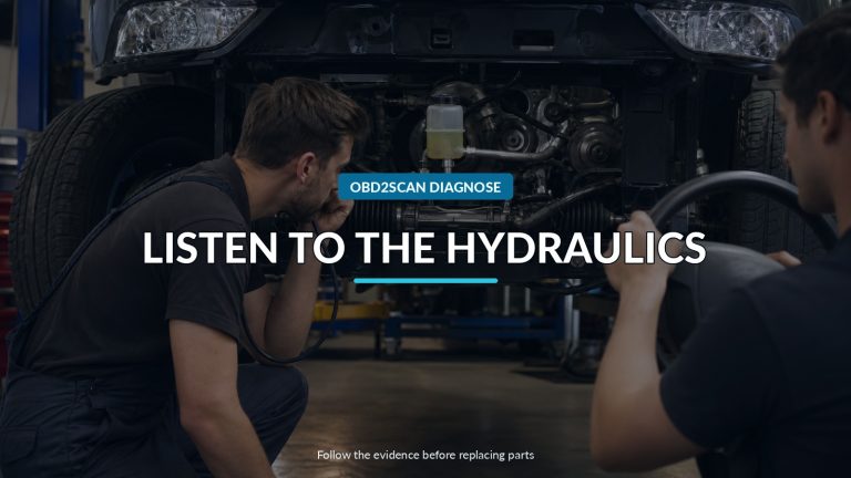
Listen during a normal request from a safe position. One side may operate while the other remains silent; a motor may run briefly and stop; a central actuator may pull a cable without releasing a seized mechanism. Sound is useful, but it does not prove clamp force has been removed.
Where supported, use the manufacturer-approved scan-tool test or service mode. Monitor commanded state, feedback, current, travel counts, and relevant wheel-side data. An overcurrent result can mean a seized mechanism, mechanical stop, wiring issue, or motor fault. An open-circuit result needs circuit confirmation.
Test power and ground at the actuator under command using the correct diagram. Some controllers reverse polarity and monitor current; applying external voltage blindly can damage a module or drive the motor farther in the wrong direction. Disconnect or isolate only as the service procedure requires.
Gate four: separate motor from mechanics
Inspect the rear brakes without assuming the motor is the failed part. Corrosion, seized caliper slides, damaged cables, overadjusted shoes, frozen mechanisms, incorrect prior service, or internal caliper faults can prevent release. A motor may be responding normally against a mechanical obstruction.
If one wheel is locked, compare both sides for sound, command, current, temperature, and mechanical condition. Do not use heat after a short attempt as proof of the original cause; repeated release commands can create their own heating.
During pad or caliper service, use the specified maintenance mode and piston procedure. Rotating or pressing an EPB piston incorrectly can damage the screw mechanism. After mechanical work, some systems require closing, initialization, travel calibration, or a basic setting before normal operation.
Decide whether temporary direct release is justified
Direct motor operation belongs after the vehicle is secured, the actuator design and connector pins are verified, the controller is isolated as specified, the required polarity and current limits are known, and the mechanical path is not obviously seized. Its purpose is temporary release for movement or further service—not bypassing diagnosis.
Use fused, controlled equipment intended for the task. Apply power only for the prescribed duration and stop if travel, sound, or current suggests a mechanical stop. Never assume the same polarity or connector arrangement across vehicles. Never leave a released vehicle without independent restraint.
If the system provides a mechanical emergency-release cable or manual procedure, follow that exact method. Some releases cannot be reset without repair or calibration. Document what was done so the next technician does not treat the vehicle as normally functional.
What not to do with an immobilized EPB
Do not drag a locked wheel, strike the actuator, reverse random pins, or repeatedly command the motor against a stop. Do not retract a piston merely to extinguish a warning. Do not erase faults before recording them, and do not trust a “released” display without confirming that the wheels can rotate as intended.
Do not frame a temporary bypass as a repair. A circuit fault, seized mechanism, low-voltage event, or calibration issue remains after the vehicle moves. The parking brake is a safety system; unresolved operation affects parking, emergency function, warning logic, and sometimes stability-control integration.
If towing is required, use the vehicle maker’s instructions for driven wheels, transmission, all-wheel-drive system, and locked brake. A flatbed or wheel dollies may be necessary.
Verify normal apply, hold, and release
After the proven fault is repaired, restore connectors and covers, perform required initialization, and clear codes only after saving the diagnostic record. Command apply and release several times while monitoring state and listening for symmetrical, controlled operation. Confirm both rear wheels release and apply as designed.
Test automatic apply or release functions only in a controlled area and according to the owner information. Verify brake-pedal and switch inputs, warning indicators, hold capability on an appropriate safe grade, and absence of overheating or drag after a short drive.
The four gates should now tell one continuous story: stable power accepted a valid command, the actuator moved correctly, and the brake mechanism released and held without force or ambiguity. That is a repair. Merely making the car roll is not.









Comments 0
Questions, fixes, and real-world diagnostic notes from readers.
Be the first to share a diagnostic result or ask a follow-up question.