
DPF Differential-Pressure Code? Separate the Hoses, Sensor, and Filter

Hose, Sensor, Or Filter?
A DPF differential-pressure code names a disagreement in the pressure story; it does not identify the liar. The story is assembled from an upstream path, a downstream path, a sensor, electrical wiring, exhaust flow, and the control module’s model of soot loading. A split hose can mimic a sensor fault. A restricted hose can mimic a filter. A genuinely restricted filter can coexist with a biased sensor.
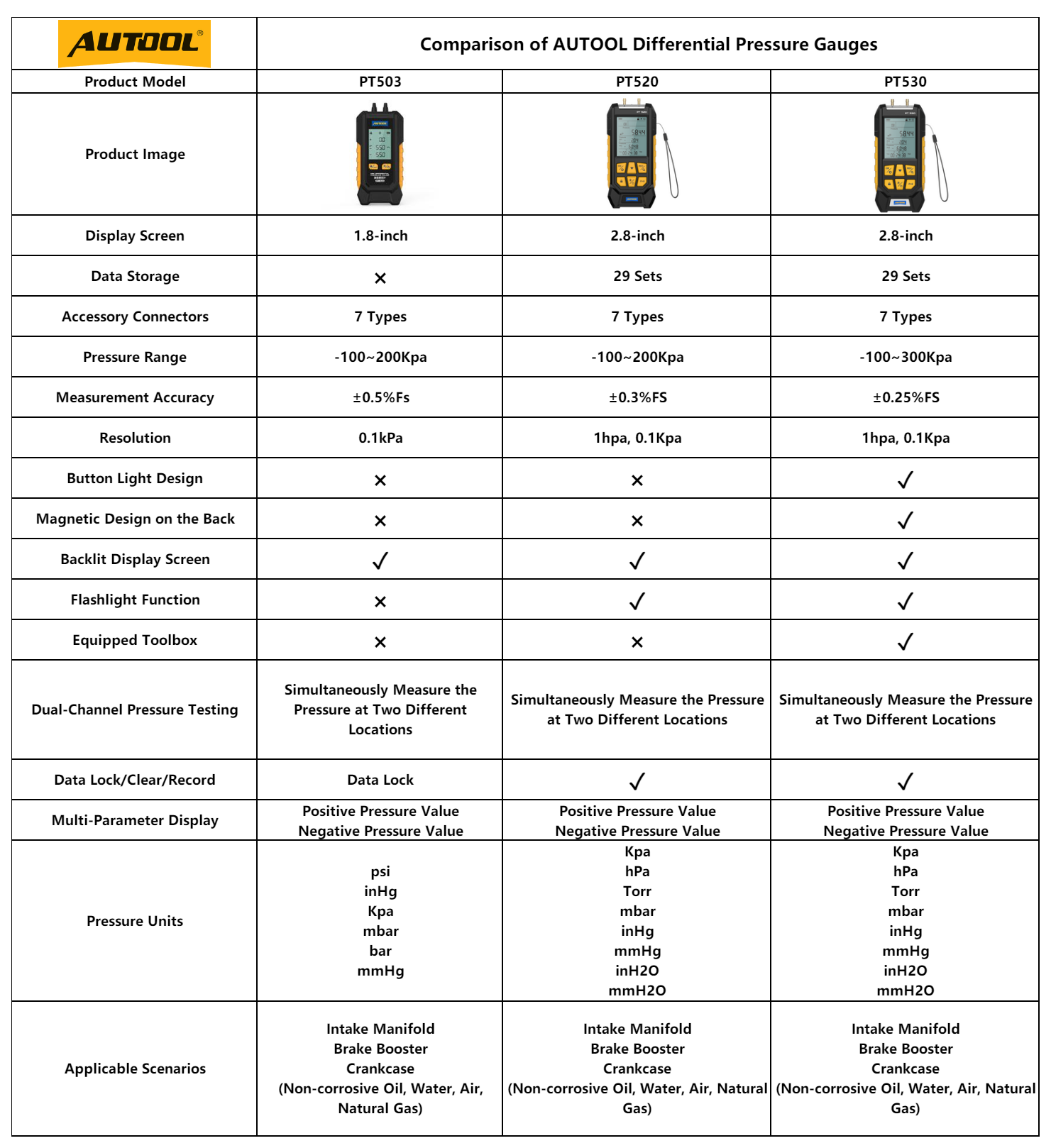
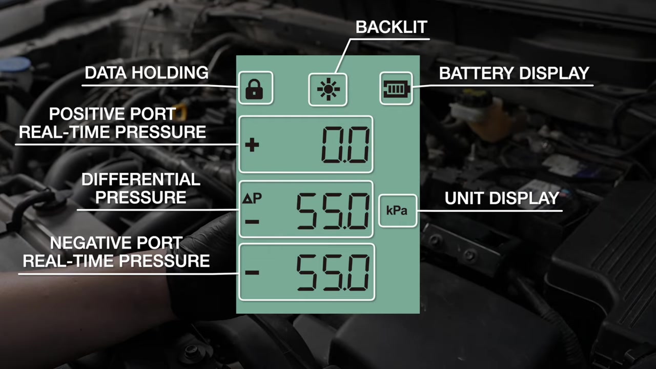
To separate the vehicle sensor’s report from the pressure that actually exists across the DPF, use an independent differential gauge connected only at service-approved points and operating conditions. The AUTOOL PT503 mini differential pressure gauge is one compact example, with positive, negative, and differential modes plus selectable units for comparing pneumatic pressure with scan data. That comparison can expose a hose, zero, or reporting disagreement; it does not supply a universal “bad DPF” number or authorize regeneration.
Treat hoses, sensor/reporting circuit, and filter/exhaust as three suspects. Keep hot exhaust, forced-regeneration, fire, and engine-damage risks outside casual testing. A restriction reading alone does not authorize replacement or regeneration.
Quick answer: A DPF differential-pressure code does not name the failed part. Save loading and temperature context, inspect both pressure paths cold, zero an independent gauge, compare it with scan data only at specified conditions, and diagnose the cause before regeneration or replacement.

In this guide
Name the three suspects
Suspect one is the pressure path: two takeoff ports and their hoses must transmit exhaust pressure without leaking, collapsing, plugging, crossing, or trapping condensate. Suspect two is the sensor and reporting chain: supply, low reference, signal, connector, module conversion, and scan data must represent the applied difference. Suspect three is the exhaust system itself: soot, ash, melted substrate, physical damage, downstream restriction, leaks, and operating conditions affect real pressure.
The same code can emerge from different combinations. A plugged upstream hose can make pressure look low when flow rises. Reversed hoses can create implausible sign or response. A biased sensor may appear plausible at idle yet diverge under controlled speed. A high real differential can reflect temporary soot loading, permanent ash capacity, a damaged filter, or another restriction. Start the lineup without deciding which face looks guilty.
| Suspect | Low-risk evidence | Common overreach |
|---|---|---|
| Hoses/ports | Routing, damage, moisture, independent flow/pressure response | Replacing the sensor without inspecting paths |
| Sensor/circuit | Key-on plausibility, supply/return, signal compared with applied pressure | Calling a scan value direct pressure proof |
| Filter/exhaust | Controlled-condition differential plus soot/ash history | Treating one generic threshold as universal |
Save soot, ash, temperature, and code context
Before clearing faults or commanding any service function, save DTC status, freeze frame, calculated soot load, ash estimate if available, distance/time since regeneration, exhaust-temperature values, differential pressure, engine load, speed, and regeneration history. Note recent repairs, oil consumption, injector problems, boost or EGR faults, and driving pattern. The filter may be the messenger for excess soot production rather than the original cause.
Distinguish calculated values from measured values. Many displays place them beside each other without explaining that one is inferred. Record key-on engine-off and running behavior only under the manufacturer’s safe test method. Ambient conditions, altitude, exhaust temperature, and engine flow can change the result. A number without its operating state is not comparable evidence.
If the vehicle is in reduced-power mode, has severe exhaust temperature faults, low oil/coolant, abnormal noise, or visible overheating, stop. Do not use a forced regeneration to erase a code before the cause is understood.
Inspect both pressure paths cold
Allow the exhaust to cool. Trace each hose from the filter takeoff to the sensor, confirming upstream/downstream routing from exact service information. Look for heat damage, soft sections, cracks at barbs, sharp bends, rub-through, crossed connections, loose joints, and condensation pockets. Inspect metal takeoff ports for deposits without pushing debris into the filter or altering calibrated passages.
Do not blast shop air blindly into a sensor or DPF line. Pressure limits and cleaning methods vary, and contamination can damage a sensor. If the procedure calls for checking hose openness, isolate components and use the specified low-pressure method. A hose that passes air on the bench can still collapse with heat or leak at a stretched connection, so condition and routing matter as much as simple openness.
Zero the independent gauge
Connect the gauge according to its manual and the vehicle procedure, with both sides at the same known atmospheric condition for zeroing. Keep hoses secure, away from hot or moving parts, and arranged so condensate cannot reach the instrument. Confirm the selected unit before comparing any record. A kPa/psi/mbar misunderstanding can create a dramatic false conclusion.
Check zero before and after the test. Drift, trapped pressure, a pinched line, or unequal hose length/condition can bias the comparison. If using a tee to compare independent gauge and vehicle sensor simultaneously, ensure the added volume and connections do not introduce leaks or response delays that matter to the procedure. An independent gauge is strongest when it measures the same physical points under the same operating condition.
Compare differential pressure by operating condition
Use the manufacturer’s specified engine speed, load, temperature, and safety method. Compare key-on plausibility, idle, a controlled raised speed, and—only where approved—loaded operation. The pattern matters: real restriction usually changes with exhaust flow. A fixed value, implausible sign, delayed return, or discontinuous jump may point back toward hoses or the sensor chain.
Do not publish or apply a single generic limit. Filter size, engine displacement, flow, temperature, sensor calibration, and control strategy differ. Compare the independent measurement with exact service data and the scan value. If both rise together beyond the allowed value under the defined condition, real restriction becomes more likely. If the gauge responds smoothly while scan data remains biased or frozen, focus on sensor/reporting evidence.
Cross-check the sensor signal
With a wiring diagram and suitable probes, verify supply and low-reference integrity before judging the signal. Compare sensor output with the independent applied differential through several controlled points if the service method permits. A signal that is correct at the sensor but wrong in scan data shifts attention to wiring, module input, scaling, or software. A correct electrical signal from a sensor connected to blocked hoses still reports the wrong physical story.
Avoid applying arbitrary pressure or voltage to the circuit. The sensor’s permissible pressure, transfer function, and pinout are vehicle-specific. A bidirectional vacuum/pressure source with accurate reference can be a specialist route, but a hand pump without control can exceed the sensor range. Keep mechanical stimulus and electrical measurement documented separately.
| Gauge vs scan result | More defensible direction |
|---|---|
| Both near zero and respond together | Reporting chain may be plausible; compare with exact operating limits |
| Gauge changes, scan value fixed | Sensor, circuit, scaling, or data path needs testing |
| Gauge high, scan value low | Sensor/path/reporting error may hide real restriction |
| Both high under specified flow | Investigate real restriction and its cause before service action |
Do not confuse soot with ash
Soot can be oxidized under the correct conditions; ash is noncombustible residue that accumulates over service life. A regeneration may reduce soot loading but cannot burn away ash. Repeated regeneration requests on an ash-loaded, damaged, oil-contaminated, or severely restricted filter can waste time or create risk. Calculated ash values are model-dependent estimates, not scales placed under the filter.
Find why loading occurred. Short-trip use, interrupted regenerations, temperature-sensor faults, boost/EGR problems, excess fueling, oil consumption, and incorrect oil can all matter. Replacement or professional cleaning decisions require service limits, inspection, history, and sometimes off-vehicle measurement. The pressure gauge contributes one coordinate; it does not certify the filter’s chemistry or remaining life.
Compare measurement routes
No auditable public model-level sales dataset supports a ranking in this niche, so compare methods. General differential manometers from Extech or Testo can provide independent pressure evidence. Sykes-Pickavant and Laser Tools offer workshop routes aimed at DPF pressure work. OEM scan tools supply commanded tests, history, and vehicle-specific interpretation but still depend on the installed sensor. PicoScope can correlate sensor voltage, pressure transducers, airflow, and time for deeper cases. A specialist cleaning/flow bench is a different method again.
| Route | Best question | Limitation |
|---|---|---|
| Vehicle scan data | What does the controller believe and command? | Relies on installed paths and sensor |
| Independent differential gauge | What pressure difference exists at these points? | Needs exact limits and safe connections |
| Scope/transducer system | How do pressure and signals change over time? | Higher skill and setup band |
| Off-vehicle specialist | Is the filter flow/capacity recoverable? | Removal, downtime, outside process |
| No-buy/outsource | Rare severe or regeneration-risk cases | Less in-house control |
If scan data cannot show whether the installed sensor and hoses are telling the truth, add an independent differential gauge and compare both stories at the same controlled operating points. A compact gauge such as the PT503 can collect that pneumatic reference without requiring a full scope/transducer system; confirm the unit, range, zero, hose routing, and vehicle limit before interpreting it.
Use a calibrated professional manometer when facility standards or local calibration support control the job. Add pressure transducers and a scope when response time must be correlated with electrical events. If the missing task is guided regeneration, learned-value reset, ash evaluation, or off-vehicle flow testing, move to the OEM or specialist route instead. The gauge solves the independent-pressure question and should not be asked to solve the rest of the DPF case.
Build a pressure-story worksheet
Use one row for each controlled state and keep independent gauge, scan pressure, engine speed/load, exhaust temperature, soot estimate, and notes on fan/regeneration state in the same row. The worksheet prevents an idle scan value from being compared with a raised-speed manometer reading taken several minutes later. Add a zero check before and after the series.
When the stories disagree, repeat only the safe point that discriminates the leading cause. If scan pressure lags but the independent gauge changes immediately, inspect pneumatic damping and signal behavior. If both change slowly, trapped condensate or hose volume may be involved. If neither responds despite increasing measured airflow under the specified test, recheck connection and test design before condemning a filter.
Decide whether the vehicle should move
An on-road load point may be more representative, but it also moves hot exhaust, a possibly restricted engine, hoses, leads, and a driver into risk. Use remote logging and the manufacturer’s road procedure only when equipment is secured and the vehicle is safe. Otherwise choose a stationary approved test or a professional facility. Better evidence is not better if collecting it can damage the filter, turbocharger, engine, shop, or technician.
Verify without forcing an unsafe regeneration
Repair the proven hose, connection, sensor circuit, sensor, or restriction cause. Reassemble heat protection and routing, clear codes only after saving evidence, and repeat the same safe operating points. Confirm gauge zero, compare independent pressure and scan values, and ensure both return and respond plausibly. Check related soot-producing faults rather than celebrating one cleared DTC.
A successful verification may be a specified drive cycle or service test, not automatically a forced regeneration. If soot loading, temperature control, oil level, fire environment, or filter integrity makes regeneration unsafe, stop and use the authorized recovery path. The final record should state the suspect eliminated, measurement conditions, applicable service limit, repair, and same-condition result. That turns a three-person lineup into evidence instead of a parts lottery.
Lineup decisions technicians commonly face
Can a clean-looking hose still be restricted? Yes. Deposits can sit inside a metal takeoff or hose, and a hose can soften/collapse hot. Use the approved openness/pressure-response procedure after the cold visual inspection; do not push debris toward the filter or sensor.
If independent and scan pressures agree, is the DPF bad? Agreement supports the measurement story. The actual value still needs the exact flow, temperature, and service limit, and the cause of soot/ash/restriction still needs diagnosis. Agreement does not authorize regeneration or replacement by itself.
Should I reset learned DPF values after replacing a sensor? Only when the manufacturer’s procedure requires it for that repair. Resets can erase useful history or tell the controller that a filter was serviced when it was not. Perform the named function with verified coverage and document it.
A practical first-pass sequence
- Save codes, temperatures, calculated loads, regeneration history, and the exact condition.
- Let the exhaust cool; inspect, identify, and route both pressure paths correctly.
- Confirm key-on plausibility and electrical supply/return without applying arbitrary pressure or voltage.
- Zero the independent gauge at atmosphere and record the selected unit.
- Compare independent and scan pressure at only the manufacturer’s safe, defined operating points.
- Use disagreement to choose hose/path or sensor/circuit tests; use agreement plus exact limits to investigate real restriction.
- Diagnose why soot or restriction developed before approving regeneration, cleaning, or replacement.
The sequence deliberately delays the high-consequence action. A forced regeneration is not a diagnostic substitute for a cold hose inspection or an independent comparison. If the first five steps cannot be completed safely, the correct route is a diesel specialist with appropriate exhaust-area controls and vehicle-specific service access.
Decision rule: Approve the next DPF action only when pressure-path integrity, sensor reporting, real differential under a specified condition, loading history, and the cause of loading tell one compatible story. If they do not, gather the one missing discriminator or escalate; do not use regeneration as the tie-breaker.








Comments 0
Questions, fixes, and real-world diagnostic notes from readers.
Be the first to share a diagnostic result or ask a follow-up question.