Automatic Transmission Shifts Harsh Only Hot? Add Line Pressure to the Temperature Story

What Changes When Hot?
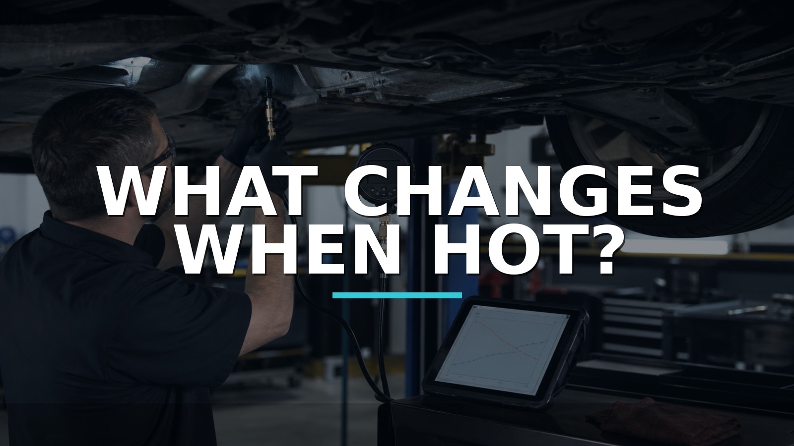
A hot-only shift complaint is not one event. Fluid viscosity changes, seals expand, solenoid resistance changes, adaptive control moves, torque-converter behavior changes, and the transmission controller commands different pressures as temperature and load evolve. The diagnosis needs a state diary that keeps temperature, gear, command, slip, and hydraulic pressure on the same page.
When service information provides a safe pressure port and specification, an independent line-pressure gauge can show whether hydraulic response matches command. The AUTOOL PT650 transmission oil-pressure gauge is one route for recording line-pressure behavior as the transmission heats and commanded states change. It does not identify which solenoid, valve, pump, seal, clutch, or controller caused the pattern.
Use only the exact test port, adapter, fluid-temperature range, gear, load, and pressure specification. Secure the vehicle on appropriate equipment and keep everyone clear during stationary loaded tests. Stop for leakage, unstable support, abnormal temperature, or any procedure beyond the available training.
Quick answer: Build a cold-to-hot diary instead of testing one static moment. Verify fluid condition and level by the exact procedure, save codes and adaptive context, log temperature and commanded state, connect a rated gauge only at the documented port, and compare pressure during the actual harsh shift.
In this guide
- Write the complaint as a state change
- Check fluid and scan evidence before opening a pressure port
- Find the exact test port and condition
- Log line pressure beside command and temperature
- Compare drive, reverse, stall, and shift events only as specified
- Separate control, solenoid, hydraulic, and mechanical causes
- Compare transmission-pressure routes
- Repeat the same hot sequence after repair
Write the complaint as a state change
Replace “shifts hard hot” with an event description: which upshift or downshift, commanded or coast, throttle/load, road speed, engine speed, fluid temperature, elapsed drive time, and whether the condition resets after key-off or cooling. Note flare, bind, bump, delay, shudder, slip, noise, or limp mode separately.
Save DTCs, freeze frame, transmission temperature, input and output speeds, commanded gear, actual ratio, converter-clutch state, pressure-control command, adaptation values, voltage, and engine torque data. A harsh shift caused by engine torque reporting or mount movement can feel hydraulic. Scan every relevant module.
Build a cold-to-hot table and mark the first temperature at which behavior changes. If the complaint appears only after a highway drive and stop, reproduce that sequence rather than warming in Park and assuming the same state.
Check fluid and scan evidence before opening a pressure port
Identify the transmission and correct fluid specification. Check level by the exact temperature, engine-running, gear-selection, and vehicle-level procedure. Many modern units have no dipstick; guessing from overflow at the wrong temperature can create overfill or underfill. Inspect color, odor, aeration, external leakage, cooler lines, and service history without declaring failure from color alone.
Verify battery and charging voltage, grounds, connectors, harness routing, cooling system, and transmission temperature sensor plausibility. Incorrect temperature data can change shift strategy and level interpretation. Look for recent fluid exchange, valve-body, software, battery, engine, axle, or mount work.
Use bidirectional solenoid or clutch tests only when supported and specified. A command result is not a pressure measurement. If scan data and service information already identify an adaptation or software procedure, complete that branch before invasive testing.
Find the exact test port and condition
Consult manufacturer diagrams and test tables. Some transmissions provide main line, clutch, governor, or converter ports; others require factory adapters, an electronic transducer, or no external pressure test at all. Do not remove a plug because it “looks like” a port. Fluid can be hot and forceful, and an incorrect plug may retain components or open a passage.
Select the PT650 or other gauge adapter by exact thread, sealing face, depth, and pressure rating. Route the hose away from exhaust, shafts, wheels, steering, and pinch points. Secure the display where a technician can read it without entering danger. Inspect for leaks at low-risk operation before loading.
Zero the gauge as instructed and confirm units. Keep the original plug and seal controlled for correct reinstallation. A broad adapter kit increases possible fit, not permission to experiment.
Log line pressure beside command and temperature
Record pressure at each manufacturer-specified state, paired with fluid temperature, engine speed, gear, brake state, throttle/load, pressure-control command, and input/output speeds. Use one row per stable state or a synchronized logger. Maximum and minimum capture can reveal an event, but only if the tool’s sampling and the event timing are adequate.
| State | Temperature | Gear/event | Command/data | Measured pressure | Symptom |
|---|---|---|---|---|---|
| Initial cold | measured | specified | saved | measured | present/absent |
| Warm transition | measured | exact shift | saved | measured | present/absent |
| Fully hot | measured | same shift/load | saved | measured | present/absent |
| Post-soak | measured | restart engagement | saved | measured | present/absent |
Do not compare a cold Reverse reading with a hot Drive specification or a high-idle event with a base-pressure table. State alignment is the whole point.
Compare drive, reverse, stall, and shift events only as specified
Base-pressure checks can reveal a broad hydraulic problem. Reverse may use different clutch circuits and pressure commands. A stall test loads the engine and transmission severely and is prohibited or tightly time-limited on many designs. Never improvise one; apply the brake, restraints, temperature limit, and duration exactly, with an escape plan.
Dynamic shift pressure may require a scope-compatible transducer or factory scan data rather than a handheld gauge. A pressure spike that accompanies a harsh shift can be commanded protection, a control error, valve-body behavior, or consequence of a slip event. Compare desired/commanded and actual evidence where available.
If pressure falls only hot while command increases, suspect supply, leakage, pump, filter, valve, or fluid paths. If pressure rises because the controller commands it after detected slip, the high pressure may be a response rather than the original cause.
Separate control, solenoid, hydraulic, and mechanical causes
Use four columns:
- Control/input: temperature, speed, torque, brake, range, software, adaptations, power and ground.
- Electrical actuator: pressure-control or shift solenoid command, resistance/current behavior, connector and harness.
- Hydraulic: fluid level/aeration, filter, pump, regulator, valve body, leakage, cooler flow.
- Mechanical/friction: clutch, band, one-way element, seal, hard part, mount, driveline play.
A resistance test when cold does not prove a solenoid’s hot current response. A commanded-duty value does not prove valve movement. Correct line pressure does not prove individual clutch pressure or friction capacity. Match each test to the column it can actually address.
Pan inspection or fluid-debris analysis may add evidence, but normal-looking fluid does not clear internal leakage and dark fluid does not identify a failed part. Avoid flushing as a diagnostic experiment when the unit has a mechanical or hydraulic fault.
Compare transmission-pressure routes
OTC, Lang, Snap-on, and factory Kent-Moore/OEM adapter routes serve traditional pressure testing. Pico WPS500X adds recorded dynamic pressure when its rating and adapters match. PT650 fits a general workshop that needs a compact digital steady-pressure kit with a broad set of transmission-oriented connectors.
No audited public model-level share data supports a market ranking. Compare pressure range, overload protection, hose temperature rating, adapter accuracy, service parts, calibration, ability to log, and access to the exact factory procedure. A transducer is worth its higher equipment and training band when pressure must be correlated with solenoid current and gear-speed data. If the unit has no approved port or the test requires a lift/dyno and specialist restraint, outsource it.
Repeat the same hot sequence after repair
Repair only the branch supported by synchronized evidence. Reinstall the test plug with the correct seal and torque, restore fluid level at the specified temperature, check for leaks, complete required adaptations or relearn, and clear saved faults only after documentation.
Drive the same cold-to-hot route with the same gear events and load. Confirm fluid temperature, commanded and actual ratio, slip, line pressure, voltage, and shift feel across the transition that previously failed. Recheck level and leakage after cooldown where specified.
The strongest conclusion describes state change: line pressure diverged from the exact hot specification while command and electrical supply were known; the proven hydraulic or electrical repair restored pressure response; and the same hot shift no longer flared or hit. A pressure number alone cannot condemn a transmission, but a well-kept pressure diary can stop a hot-only fault from hiding behind a cold road test.