
Motorcycle ABS Light On? Use Code, Battery, and Wheel-Speed Evidence in Order

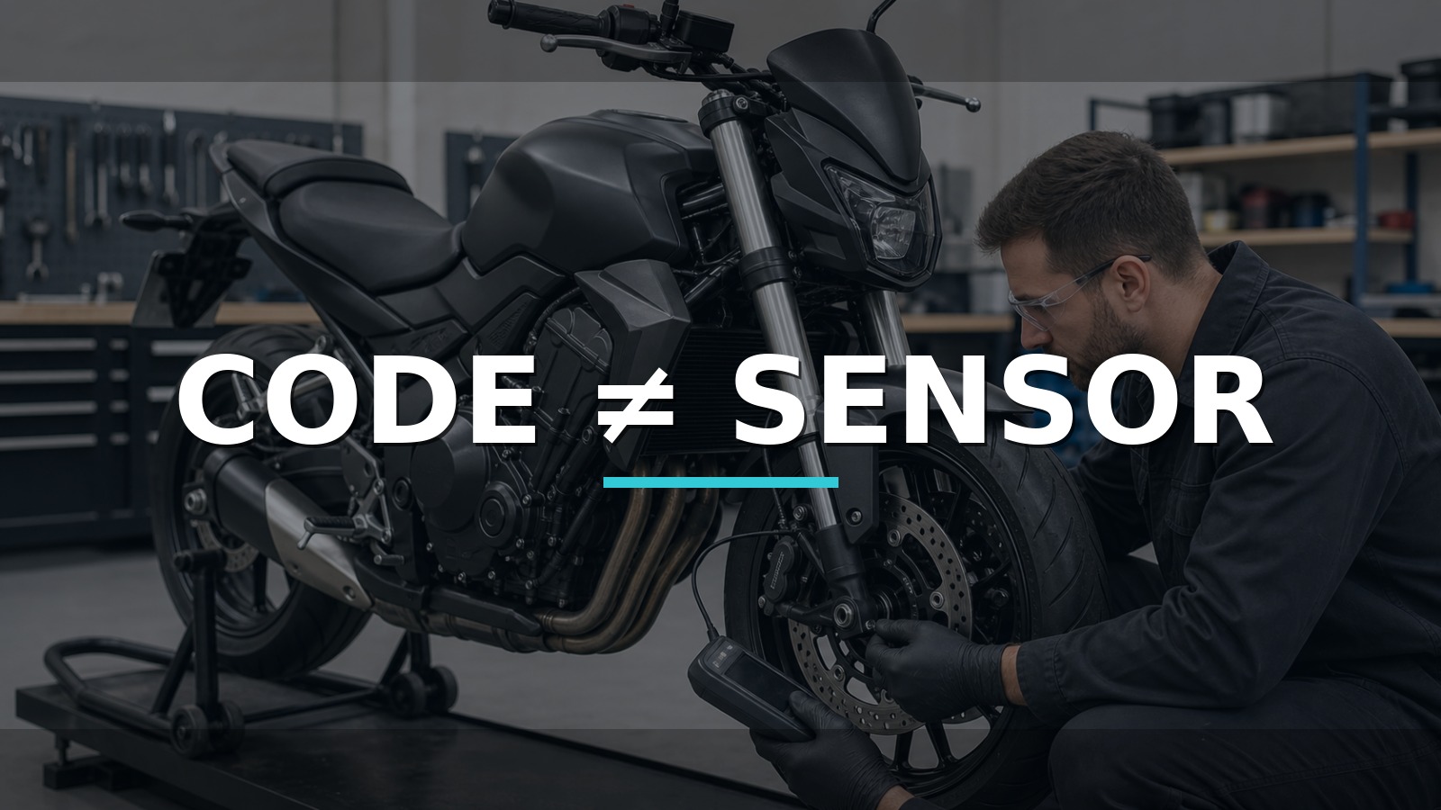
Code ≠ Sensor
An ABS code naming a wheel identifies a monitored circuit or behavior; it does not sentence the sensor. The same branch can include battery voltage, sensor supply, connector, harness, air gap, tone ring/encoder, wheel bearing, tire size, module input, and a fault that appears only after the motorcycle begins moving.
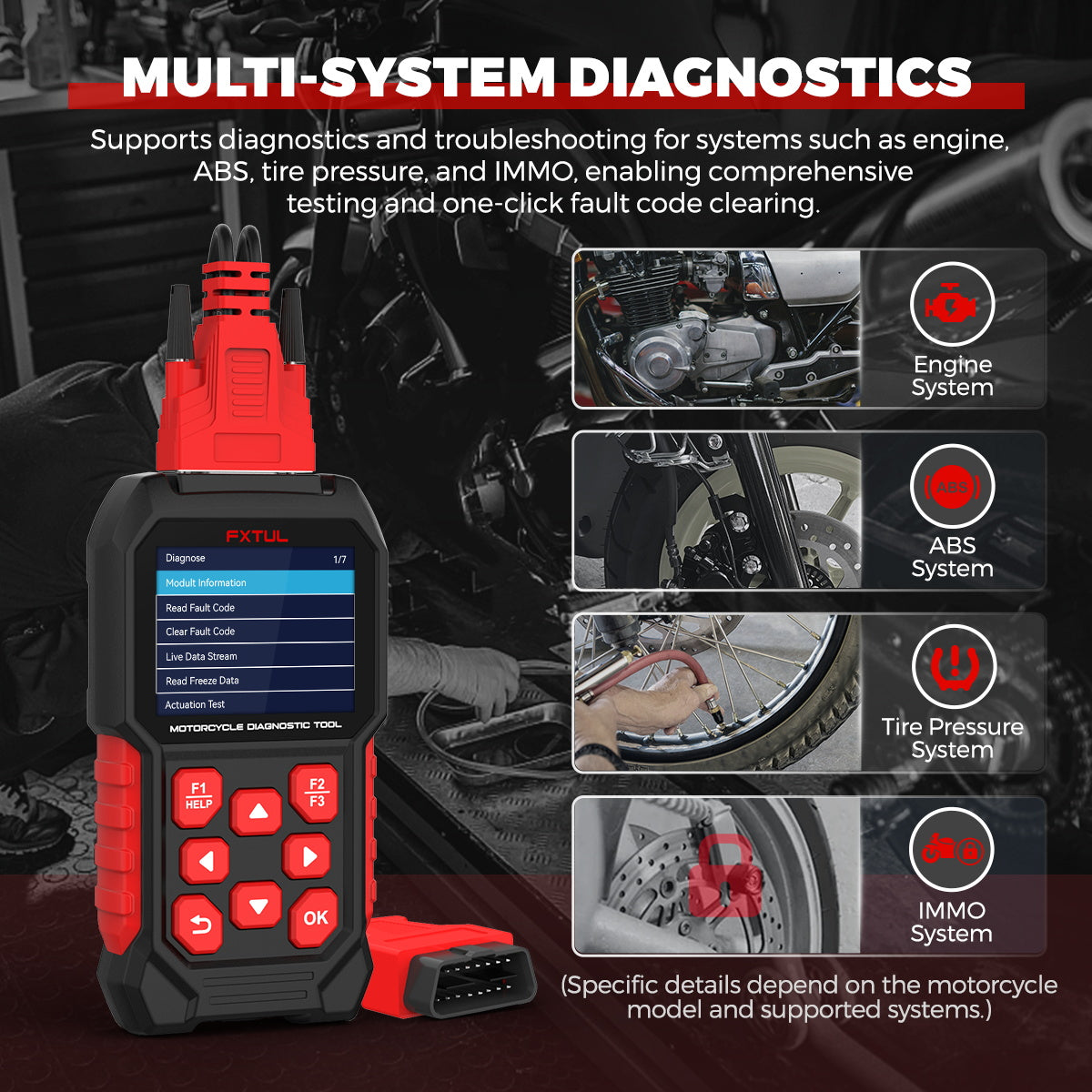
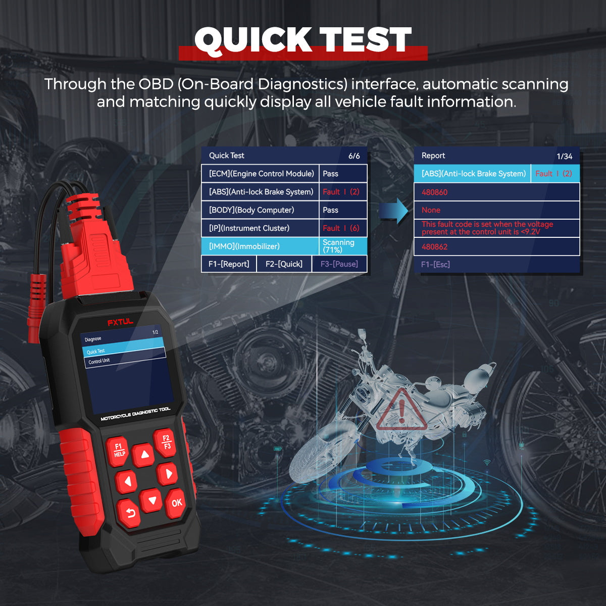
To turn an ABS warning lamp into usable evidence, use a motorcycle scanner whose current coverage explicitly includes the bike, ABS ECU, connector, region, and functions needed for the test. Where that match is confirmed, the FXTUL M4 Asia motorcycle diagnostic scanner is one portable route for reading codes and, on supported systems, comparing live wheel-speed and service data. Coverage is the gate: a familiar connector or brand name does not prove access to the ABS function on the motorcycle in front of you.
Braking faults and unstable support are stop conditions. Do not spin a driven wheel on a stand or road-test outside the manufacturer’s safety procedure. This fault tree begins with rider safety, then branches by when the light appears.
Quick answer: A wheel-named ABS code does not prove the sensor failed. Check base-brake and wheel safety, preserve codes, confirm battery context, inspect ring/gap/harness and recent wheel work, compare live speeds safely, then test the identified sensor type correctly.
In this guide
- Decide whether the motorcycle is safe to move
- Record when the ABS light changes
- Confirm battery and charging context
- Read all ABS codes before clearing
- Compare live wheel speeds safely
- Inspect ring, gap, wiring, and wheel work
- Separate sensor circuit from module and hydraulic faults
- Compare motorcycle scan routes
Decide whether the motorcycle is safe to move
Many systems illuminate the ABS lamp at key-on and switch it off only after a self-check or after wheel movement. Confirm the normal behavior from the owner/service manual. Record whether the lamp never extinguishes, returns immediately, returns at a repeatable speed, appears after bumps or steering movement, or began after battery, tire, bearing, brake, fork, or chain work.
Check actual braking feel, fluid level where visible, leaks, damaged lines, loose caliper hardware, tire condition, wheel installation, and warning combinations before diagnostic operation. If conventional braking is impaired or any part is insecure, do not ride. ABS may be unavailable even when base brakes feel normal; the rider must be informed and local safety rules followed.
| Lamp/code timing | First branch | Why it matters |
|---|---|---|
| Present at key-on | Power, ground, stored/current electrical fault, coverage | No wheel rotation needed to fail |
| Returns only after moving | Wheel-speed plausibility, air gap, encoder, tire/wheel | Dynamic comparison matters |
| Appears over bumps/steering | Connector/harness strain or intermittent power | Preserve movement condition |
| Began after wheel service | Installation, sensor clearance, encoder/bearing orientation | Recent change is high-value evidence |
Record when the ABS light changes
Identify the correct diagnostic cable and connector, stabilize the motorcycle safely, and run a complete supported scan. Save exact ABS DTC, status, freeze frame, module identification, battery voltage, and related engine/body codes. A low-voltage event may set multiple historical faults. Clearing first removes timing and can make an intermittent problem wait for the next ride.
If M4 does not recognize the model or function, update by the documented method and verify the coverage listing. FXTUL’s current page directs users to provide logs when recognition fails. Treat that as a coverage/support branch, not evidence that the motorcycle network is broken. Try another known-compatible tool only if it can be connected without changing the fault state.
Confirm battery and charging context
Motorcycle batteries have little reserve, and cranking or charging faults can reset an ABS module. Measure battery condition and voltage under the service procedure, inspect terminals and grounds, and check charging behavior at the specified speed/load. Do not substitute one generic voltage for battery chemistry and model data. The M4’s listed DC operating range describes the tool, not the ABS module’s acceptable supply.
Inspect shared grounds and fuses. After battery replacement or disconnection, some systems require movement, initialization, steering-angle calibration, or code handling; others recover automatically. Follow model-specific instructions rather than repeatedly cycling the key.
Read all ABS codes before clearing
Look at sensor mounting, connector lock, harness clips, routing through fork or swingarm travel, chafing, pinching, contamination, and impact. Inspect the tone ring or magnetic encoder for cracks, bent teeth, debris, incorrect orientation, missing sections, and damage from tools. Confirm bearing play and wheel seating. A sensor mounted correctly against a damaged encoder will report bad speed honestly.
Check air gap and mounting only with the exact procedure. Magnetic encoders may be integrated into a bearing seal and can be installed facing the wrong direction. Tire circumference or mismatched wheel size can create plausibility faults even when both sensors generate signals. Do not clean a magnetic ring with tools that damage it or assume a visual tooth count applies to an encoded seal.
Compare live wheel speeds safely
With the motorcycle securely supported by the approved method, observe front and rear wheel-speed data at safe low movement or during an authorized road test. Never run a driven wheel at speed on an unstable stand. A helper must not place hands near chain, sprocket, brake, or rotating wheel. If the safe method requires professional equipment, outsource.
Compare onset, smoothness, dropouts, and ratio rather than chasing one exact number. A value fixed at zero can reflect sensor, circuit, encoder, or coverage. A speed that appears then drops at one wheel position suggests a local encoder/gap issue. Both speeds that disagree consistently can point to tire size or scaling. Save a graph if the scanner supports it.
Inspect ring, gap, wiring, and wheel work
Identify whether the sensor is passive inductive, active Hall/magnetoresistive, two-wire current-modulated, or another design. Resistance testing can be meaningful on some passive sensors and meaningless or damaging on active ones. Verify supply, return, and signal/current using the service diagram and suitable equipment. Do not inject voltage.
A scope can observe waveform amplitude, shape, frequency, bias, current modulation, or dropout while the wheel turns safely. Compare left/right or front/rear only when designs and tooth counts are comparable. A strong sensor waveform at its connector but a missing scan value moves the investigation toward harness/module input or software interpretation.
| Evidence combination | More defensible conclusion |
|---|---|
| DTC names wheel, physical encoder damaged | Repair encoder/mechanical cause, then verify signal |
| Live data drops, waveform drops at same position | Sensor-gap/encoder path is localized |
| Waveform reaches module, scan value absent | Module input/logic/coverage needs specialist test |
| Both speeds smooth but ratio wrong | Tire/wheel scaling or configuration branch |
Separate sensor circuit from module and hydraulic faults
The scanner is best for module identity, DTC context, live speed, supported active/service functions, and post-repair clearing. A meter checks supply and ground. A scope proves the physical wheel-speed signal and intermittent behavior. Mechanical measurement confirms gap, runout, bearing, and installation. No single tool covers all four layers.
If the code and live data already localize an encoder damaged during wheel work, a scope may add little. If the sensor and ring look perfect but the value drops only at one speed, waveform capture becomes valuable. If the M4 lacks exact coverage, more probing will not fix the software gap; use another verified platform or dealer-level route.
Compare motorcycle scan routes
No auditable public model-level sales dataset supports a market-share claim. TEXA Bike and Jaltest Bike offer broad professional ecosystems; GS-911 specializes in supported BMW applications; OBDSTAR and HealTech cover other multi-brand or dedicated routes; OEM dealer tools provide the controlling depth for their brands. Adapter cables, subscriptions, and regional model lists can decide the real working band.
| Route | Best fit | Tradeoff |
|---|---|---|
| FXTUL M4 Asia | Listed Asian/other applications and portable code/data work | Compatibility must be verified per model/function |
| Professional multi-brand platform | High bike volume, guided coverage, support | Higher equipment/subscription band |
| Brand specialist/OEM | Deepest supported brand procedures | Narrower brand or restricted access |
| Scope plus meter | Physical sensor/circuit proof | Does not read ABS logic/codes alone |
| Outsource/no-buy | Rare ABS work or unsafe test setup | Less in-house turnaround |
If the missing evidence is an ABS code, freeze frame, or live comparison between wheel speeds, choose a motorcycle scan route that explicitly covers the exact bike and ABS ECU. The M4 Asia can fill that role on supported applications, making it possible to see whether one reported wheel speed drops out before disturbing the sensor or harness. Confirm the current software, cable, system, and function rather than assuming that engine communication guarantees ABS access.
Choose TEXA or Jaltest when broad workshop coverage, guided procedures, reporting, support, and throughput justify a professional platform; use OEM or brand-depth tools where deeper functions control the job. When the unanswered question is the physical sensor waveform rather than module data, a correctly connected scope is the relevant next instrument regardless of scan-tool brand.
Use a wheel-service before/after checklist
For faults after tire, bearing, fork, or brake work, compare axle/spacer order, sensor fastener, harness clips, tone ring/encoder orientation, bearing seating, wheel direction, tire size, and connector lock with the service information. Photograph both sides before disassembly when possible. Many “sensor failures” are geometry or assembly changes that the sensor reports correctly.
If live speeds differ, compare the wheel circumference and encoder design before assuming electronic scaling. A new tire, wrong profile, or mixed wheel can alter ratio. Never grind a sensor mount or bend a ring to chase a generic air-gap number; use the exact specification and repair method.
Plan a safe dynamic capture
Choose the lowest-risk method that can reproduce the dropout. A hand-rotated non-driven wheel on a secure approved stand may be enough for a gross signal check. A driven-wheel test, brake application, or road capture may require a trained rider, secured logger, controlled route, and second person—never a handheld screen watched while riding.
Set graph scale and sample rate before movement, mark the event, and stop after one useful capture. Compare signal loss with speed data and warning timing. Do not repeatedly trigger ABS intervention to prove a repaired speed input unless the OEM verification specifically requires it and conditions are safe.
Separate code clearing from initialization
Clearing a DTC may remove history but may not complete steering-angle, tire-circumference, pressure, or ABS initialization. Conversely, some lamps clear only after valid wheel movement. Follow the exact post-service steps and confirm the scanner has that function. An unsupported “success” message from the wrong model menu is not evidence.
Verify at rest and during the approved road check
Restore sensor fasteners, clearance, harness clips, connector seals, wheel/bearing installation, tire setup, and battery grounds to specification. Remove temporary test leads. Clear the ABS code only after the original evidence is saved, then perform the manufacturer’s stationary checks, initialization, and controlled movement requirement.
Confirm both live wheel speeds are plausible and smooth, the lamp follows normal key-on/movement behavior, codes do not return, and conventional braking remains safe. Reproduce the bump, speed, temperature, or post-service condition that opened the original branch. The final note should name whether the root was power, mechanical target, sensor/circuit, module path, or tool coverage—not simply “ABS sensor code cleared.”
Rider questions at the decision point
Can I keep riding if normal brakes feel okay? ABS availability and legal/safety guidance vary, and an illuminated lamp may accompany a deeper braking fault. Inspect for conventional brake danger first, consult the owner/service information, and do not ride when braking, wheel installation, or stability is uncertain.
Does cleaning the sensor fix magnetic debris? Cleaning may remove debris, but find the source and inspect the encoder/bearing. Metal accumulation can indicate wear. Use compatible cleaning and do not scratch a magnetic ring or change the specified air gap.
Can I clear the code to see if it returns? Save it first. A history code after low battery may clear and stay away, while a current electrical or mechanical fault will return. Clearing is a controlled diagnostic step only after safety inspection and evidence capture.
A safe fault-tree order
- Inspect base-brake safety, wheel security, tire condition, and leaks before diagnostic movement.
- Classify lamp timing and record recent battery/wheel/brake work.
- Save exact ABS codes, module identity, voltage, and supported live data.
- Prove battery/charging and shared grounds under the model procedure.
- Inspect the named wheel’s sensor, harness, gap, ring/encoder, bearing, and tire/wheel setup.
- Compare live speeds using the lowest-risk approved movement.
- Identify sensor type before meter/scope testing and never inject voltage.
Only after these branches should a sensor be replaced. If replacement is indicated, confirm part revision, mounting cleanliness, air gap procedure, connector seal, and harness routing through full steering/suspension travel. A new sensor rubbing the ring or stretching at full lock can create the next fault. Verification must include the movement threshold that extinguishes or re-lights the warning, not only a stationary code clear.
Decision rule: A wheel-named code authorizes inspection of that branch, not replacement of its sensor. Require one confirming link—physical damage, repeatable live-data dropout, matching waveform loss, or failed specified circuit test—then verify lamp behavior after safe movement. When scanner coverage is uncertain, confirm coverage before using missing data as vehicle evidence.
Record connector seals and harness routing in the release photo set. A sensor circuit that passes with the fork centered may fail at full lock or suspension travel. Verify allowable movement statically by the service procedure before any road check, without placing hands near a rotating wheel.





Comments 0
Questions, fixes, and real-world diagnostic notes from readers.
Be the first to share a diagnostic result or ask a follow-up question.