
How to Use a Wheel Alignment Machine: AUTOOL XC508 Step-by-Step Guide

The AUTOOL XC508 does not make an alignment trustworthy by itself. A reliable result comes from preparing the vehicle and rack, mounting the clamps and targets correctly, selecting the exact vehicle data, following compensation prompts, then rechecking the readings and road-testing the original complaint.
Short answer: treat the XC508 as a measurement guide, not a pass/fail oracle. A green value only means the reading is within the selected on-screen tolerance; it does not rule out worn parts, tire pull, or an off-center steering wheel.
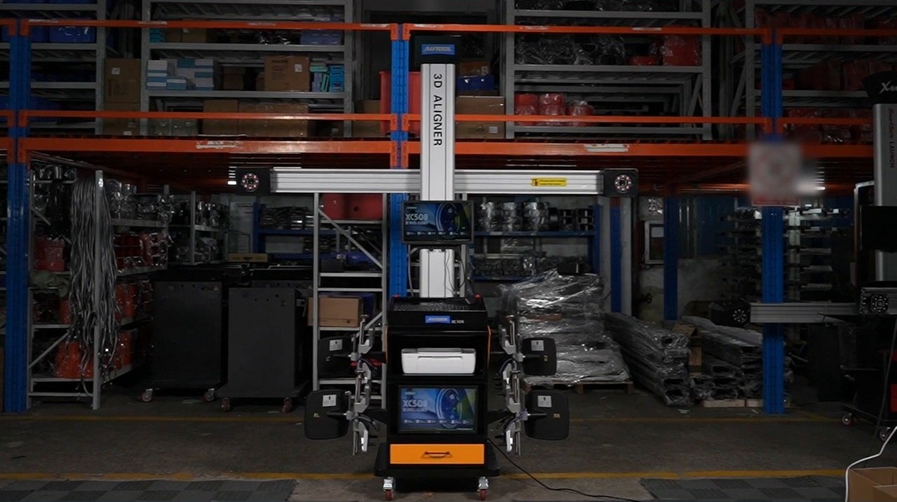
This illustrated guide walks a trained technician through the routine XC508 workflow. It does not cover lift training or service calibration, and it is not an independent accuracy test. Use the current XC508 screen, OEM service information, and your shop’s safety procedures when they differ from this overview.
What you will accomplish
By the end of the procedure, you should have:
- a mechanically suitable vehicle and a safe, ready alignment bay;
- four stable clamps and correctly identified targets;
- valid target images and accepted rolling compensation;
- any camber, caster, toe, thrust-angle, or SAI/kingpin measurements required by the selected procedure;
- adjustments made against current vehicle-specific specifications;
- repeatable before/after values, a saved report, and a road-test decision.
The six-phase workflow at a glance
| Phase | Purpose | Proof that the phase is complete |
|---|---|---|
| 1. Prepare | Understand the complaint and make the vehicle/bay fit to measure | Vehicle, rack, plates, tires, and suspension are ready |
| 2. Install | Build the physical measurement system | Four clamps and four targets are secure and identified |
| 3. Establish data | Tell the XC508 exactly what vehicle it is measuring | Correct vehicle data is selected and targets are readable |
| 4. Measure | Compensate for wheel/clamp runout effects and capture the required geometry | Compensation and required angle sweeps are accepted |
| 5. Adjust and document | Correct the cause, then prove the correction | Stable recheck values and a traceable report exist |
| 6. Verify and close | Confirm the customer outcome and protect the equipment | Road-test decision is recorded and the bay is safe |
The sequence mirrors the routine XC508 operating logic. For the current downloadable file, open the AUTOOL Store manual download library, choose 3D Wheel Aligner Machine, and confirm AUTOOL XC508 before downloading. Software labels and database contents can change by version and region.
In this guide
Before you start: safety and fit checks
Only a qualified, trained operator should perform a wheel alignment on a raised vehicle. Complete your lift and alignment-rack safety checks before positioning or raising the vehicle. Use a grounded, suitable power supply; keep the rack secure and within its stated level tolerance; keep targets and camera optics clean; and control direct sunlight or reflections that interfere with target recognition.
The standard XC508 rim range is stated as 10–23 inches on current official product information. Treat any special 24-inch configuration as a support-confirmed exception, not as an automatic promise. Confirm the rack, turn plates, rear slip plates, bridge, rolling space, target clearance, power, and software/database status before accepting a job.
Current official product information says the XC508 targets do not require routine calibration. If the column or cameras have been moved, the equipment has been altered, or readings are not repeatable, stop routine operation and contact authorized AUTOOL support. Do not use a service-calibration sequence as a daily setup step.
Phase 1 — Prepare the bay and vehicle
Step 1: Capture the customer complaint and vehicle identity
Start with the driver’s symptom, not with the alignment screen. Ask whether the vehicle pulls left or right, whether the steering wheel is off-center, whether the tires wear unevenly, and whether suspension, steering, tire, collision, or alignment work was recently performed. Record the make, model, year, market, drivetrain or suspension variant when relevant, and the previous alignment history.
Why this matters: the readings must be interpreted against the correct vehicle condition and the driver’s actual complaint. Values can be inside the selected tolerance while tire condition, road crown, thrust angle, or steering-wheel position still causes a concern.
Completion check: the job card identifies the vehicle and complaint before the car is lifted.
Common mistake: choosing a familiar vehicle entry later because it looks close enough. Similar names can represent different years, markets, engines, suspension packages, or reference values.
Step 2: Inspect tires, suspension, and steering before measuring
Check cold tire pressure, tire size, tread condition, left/right matching, and visible damage. Inspect wheel bearings, control arms or wishbones, ball joints, bushings, shocks, tie rods, and steering components for looseness or wear. Check for seized adjusters, bent parts, ride-height changes, or collision damage.
Why this matters: the aligner measures the geometry that exists at that moment; it cannot make a loose bearing, worn joint, damaged tire, or seized adjuster serviceable. If a defect can affect safe measurement or adjustment, stop, record it, and repair it before continuing.
Completion check: every defect that could affect the measurement or adjustment is recorded, and the vehicle is approved for measurement by the responsible technician.
Common mistake: using the aligner to diagnose a worn component after the adjustment has already started. That creates a report with numbers but no trustworthy mechanical baseline.
Step 3: Make the rack, turn plates, and rear slip plates ready
Inspect the alignment rack and confirm that it is secure, clean, suitable for the vehicle, and within the rack or aligner manufacturer’s stated level tolerance. Place the front turntables and rear slip plates as required by the rack procedure. Account for locking pins, bridge pieces, wheel restraints, and the full rolling path before moving the vehicle.
Plate and restraint states change during positioning, rolling compensation, measurement, and release. Follow the current XC508 prompt together with the rack manufacturer’s procedure, and confirm the required state before every vehicle movement.
Completion check: the vehicle’s approach path and the short rolling path are clear; the operator can name which plate locks are engaged for the current phase.
Common mistake: leaving a turntable or slip plate locked during an operation that requires it to float. The result may look like a sensor problem when the mechanical path is the real problem.
Step 4: Position the vehicle, center the steering wheel, and lift
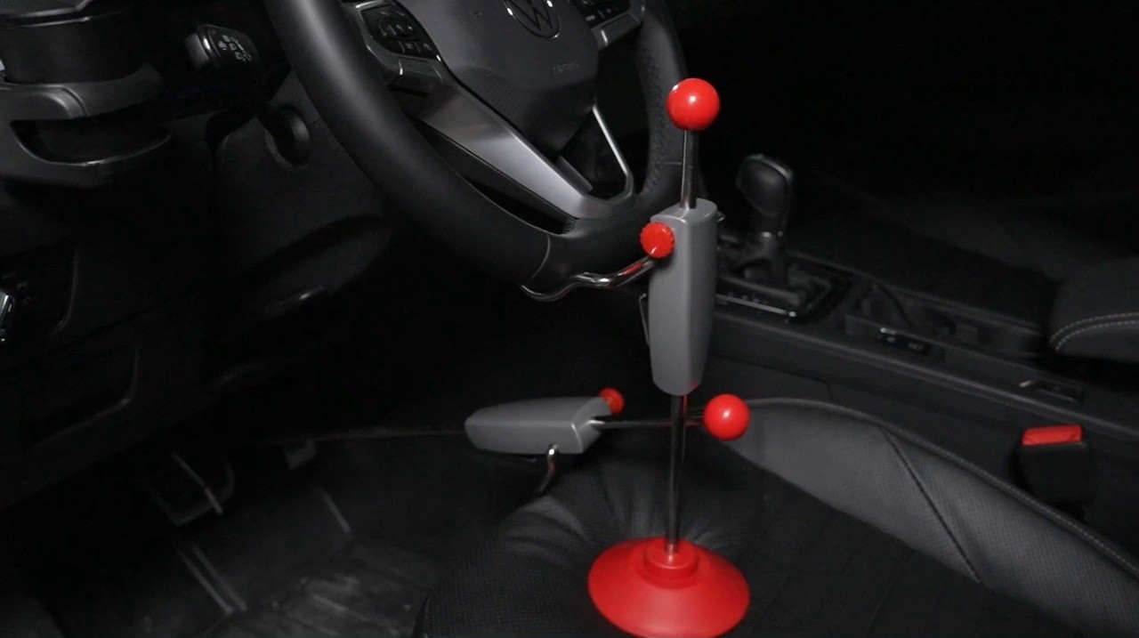
Drive the vehicle onto the rack with the front wheels close to the turntable centers. Stop smoothly. Center the steering wheel, install the steering-wheel holder when the procedure calls for it, place the rear wheel restraints, and release the handbrake only in the controlled sequence required by your lift and alignment procedure. Raise the vehicle to the alignment height while maintaining stability.
Why this matters: the steering-wheel position and the vehicle’s freedom to move are part of the reference frame. A steering wheel that moves during compensation or angle measurement can invalidate the result.
Completion check: the vehicle is stable at alignment height, the steering wheel is held when required, and no person or object is inside the movement path.
Common mistake: pressing the brake or leaving the handbrake applied during an operation that requires controlled rolling, or releasing restraints before the vehicle is stable.
Phase 2 — Install the physical measurement system
Step 5: Mount all four wheel clamps
Fit one clamp to each wheel in the correct position. Seat the jaws firmly on the rim, avoid clamping a fragile cosmetic edge when the supplied hardware provides a safer contact, and check that each clamp is square and stable. Do not bump or push a clamp after it has been accepted by the measurement process.
Why this matters: the clamp is the mechanical link between the wheel and the target. A tilted, loose, or shifted clamp can create a result that changes when the hardware is touched.
Completion check: all four clamps are secure, the jaws are seated, and a light stability check shows no looseness or shifting.
Common mistake: tightening one clamp while the target is already being viewed, then forgetting to repeat the visibility or compensation check.
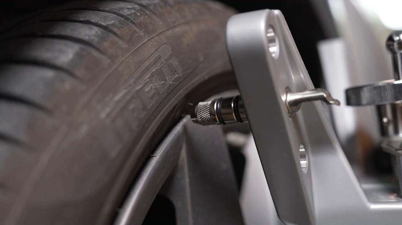
Step 6: Mount each target to the matching wheel position
Attach the target plates to the four clamps. Confirm front/rear and left/right identification rather than relying on memory. Keep the plates upright and perpendicular to the ground as far as the hardware allows. Remove dirt, grease, tape, and anything that can cover the target pattern.
Why this matters: the cameras must identify each target pattern and position. A target on the wrong wheel, an obstructed pattern, or unstable hardware prevents a valid image and must be corrected before measurement.
Completion check: four targets are mounted, their identities match the vehicle positions, and every target is clean and physically stable.
Common mistake: swapping left and right targets after a tire or clamp inspection. If the system cannot reconcile the image with the expected position, stop and correct the hardware rather than clicking through the warning.
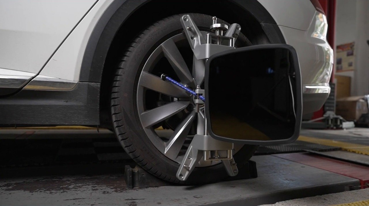
Step 7: Power up and open the alignment software
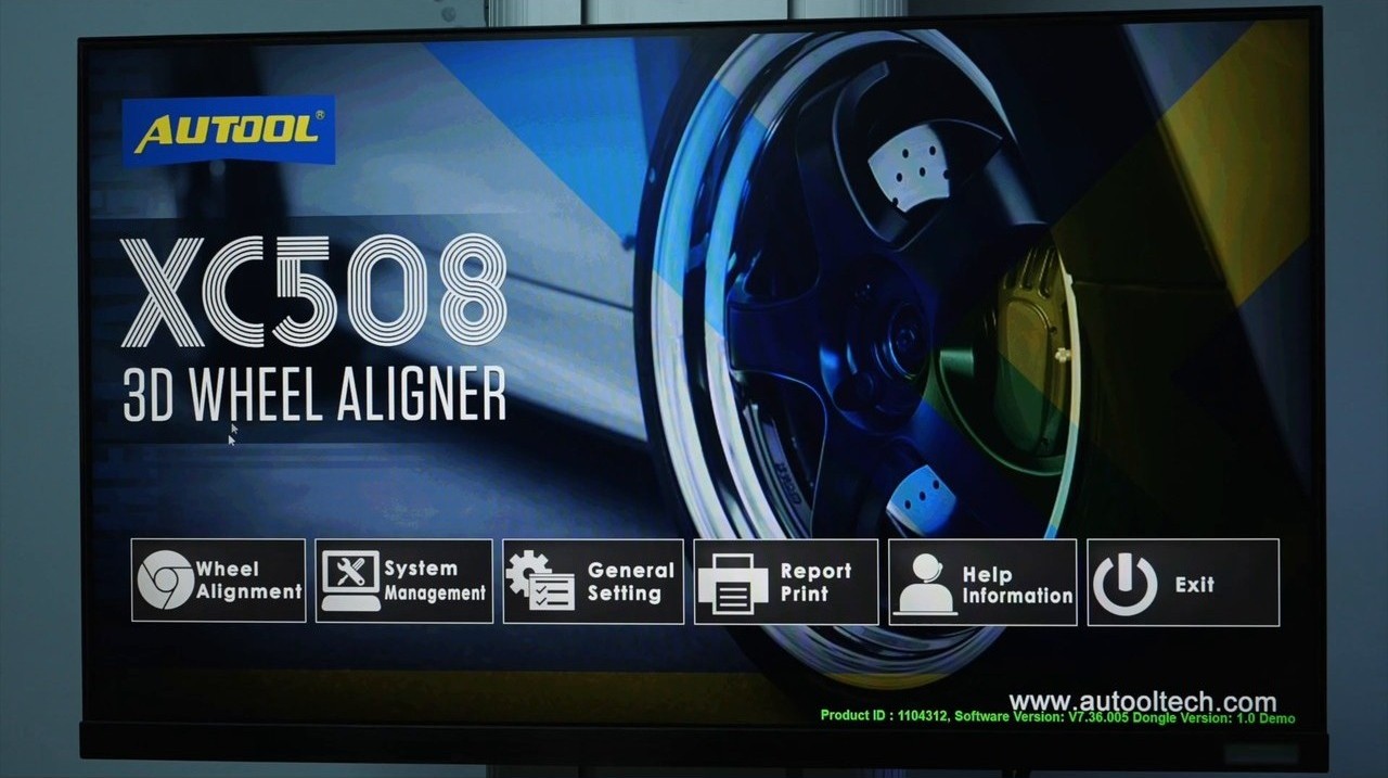
Check the computer-to-crossbeam data and power connections. Turn on the main power and displays, wait for the operating system to finish loading, and open the XC508 alignment program.
Why this matters: an alignment system is a combination of cameras, computer, targets, clamps, and software. A loose cable or partially started program can look like a target or database fault later in the workflow.
Completion check: the main alignment interface is visible and the system is ready to create or select a measurement job.
Common mistake: moving the crossbeam or targets while the application is still starting, then treating the first unstable image as a calibration failure.
Phase 3 — Establish valid measurement data
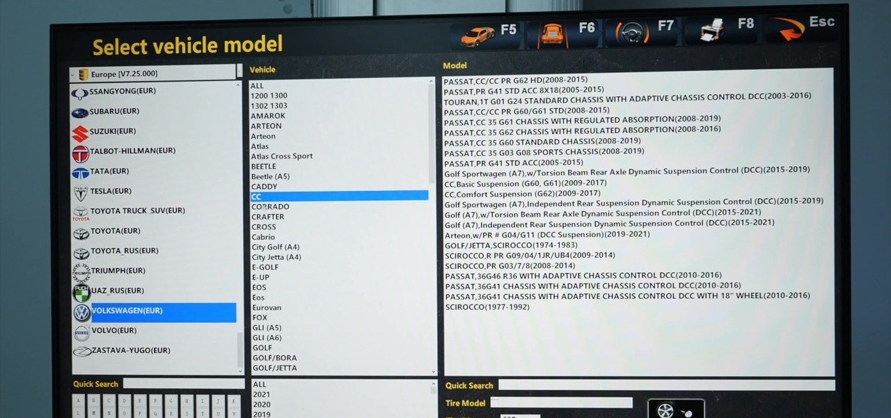
Step 8: Start a job and select the exact vehicle data
Choose the manufacturer, model, year, market, and relevant configuration. Use the database search or index deliberately. If the workshop has a verified user-defined specification, label it clearly and preserve the source; do not silently substitute it for an OEM value.
Confirm whether the selected values come from the built-in vehicle database or a shop-defined record. Verify the record against current vehicle repair information, including market, load condition, ride height, adjustment points, and limits, before using it as the job reference.
Completion check: the vehicle shown on screen matches the job card, and the reference values are appropriate for the market, year, and configuration.
Common mistake: selecting a similar model to unlock the Next button. If the exact vehicle is missing, stop and resolve the data question before measuring.
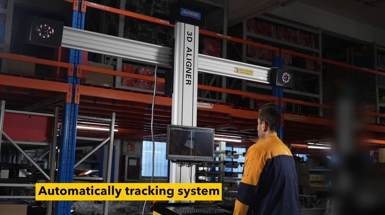
Step 9: Bring the camera crossbeam onto the targets
Continue to the target-monitor stage and let the height-tracking system bring the cameras into view of the targets. Keep people, tools, and loose cables away from the beam’s travel path. If tracking stops or a target is not found, inspect the physical scene before trying again.
Why this matters: the camera must see the intended target pattern from a usable position. A blocked, dirty, poorly lit, or incorrectly mounted target cannot be made valid by repeatedly pressing Next.
Completion check: the crossbeam is positioned for the four targets and the software shows a usable image for every wheel position.
Common mistake: standing between the camera and a target while trying to help the system “find” it. Move the obstruction, not the target geometry.
Step 10: Use Target Monitor as a validity gate
Inspect all four target images before accepting the screen. Each target should be identified, centered in its expected view, and readable. Use the current on-screen guidance and installed help for any version-specific image indicators; do not copy display values from another software release.
If a target is red, blocked, missing, or visibly off-center, stop. Check target orientation, clamp seating, camera/target cleanliness, reflections, direct sunlight, and anything between the camera and target. Correct the cause and repeat the validity check.
Completion check: every target is accepted by the monitor and the operator can explain any warning before moving the vehicle.
Common mistake: treating a red target as a cosmetic display issue. An invalid image is a measurement stop condition.
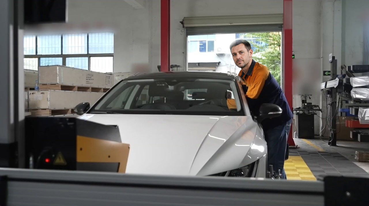
Step 11: Prepare the steering wheel and plates for rolling compensation
Before rolling compensation, read the current XC508 prompt and set the steering reference, plate locks, bridge pieces, wheel restraints, and brake state for the movement it requests. Confirm that the vehicle can complete the prompted roll without contacting hardware or entering an uncontrolled path.
Why this matters: rolling compensation is intended to reduce errors caused by rim, tire, and clamp runout. It only helps when the vehicle and steering reference move in a controlled way.
Completion check: the steering wheel is locked, the rolling path is safe, and the hardware state matches the current compensation prompt.
Common mistake: allowing a helper to steer or touch the wheel during the compensation samples.
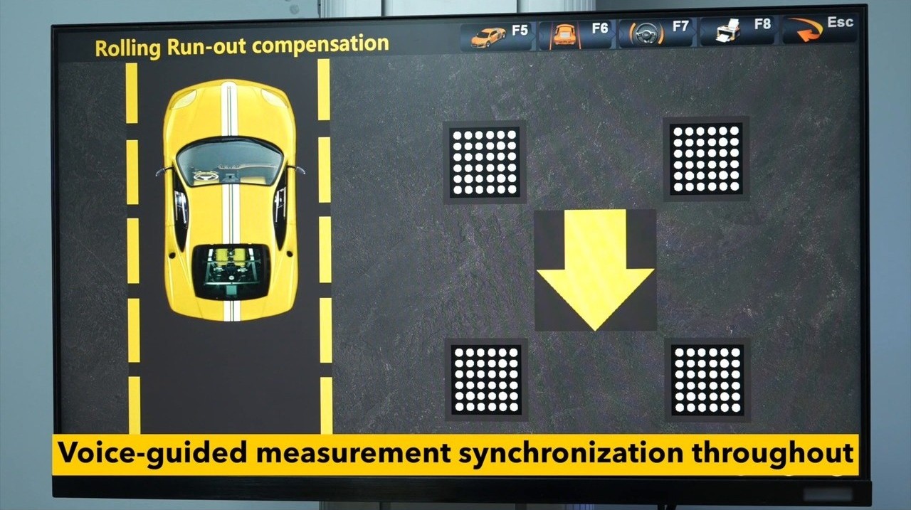
Step 12: Complete rolling compensation exactly as prompted
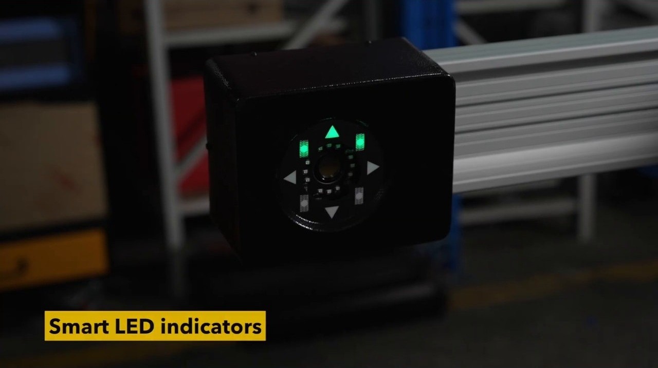
Follow the arrows and LED guidance. Push the vehicle smoothly through the short movement requested by the installed software, without sudden acceleration, braking, sideways force, or target contact. Stop when the XC508 accepts the samples. Do not substitute a distance copied from another software version, manual, or tutorial for the current on-screen prompt.
Rolling compensation helps account for wheel/clamp runout effects; it does not replace the mechanical pre-inspection. Stop if the vehicle path, restraint state, target visibility, or operator control is unsafe or unclear.
Completion check: the compensation step is accepted and all four-wheel data becomes available for the next measurement stage.
Common mistakes:
- moving too quickly or too far;
- allowing the steering wheel to move;
- leaving a lock engaged when the current procedure requires a free plate;
- continuing after a target becomes red or blocked;
- assuming that a single accepted pass proves repeatability.
Phase 4 — Measure and interpret the geometry
Step 13: Restore the measurement state after compensation
When the software accepts compensation, follow the current screen and rack procedure to place the turn plates, rear slip plates, bridge pieces, and restraints in the state required for live measurement. Recheck every clamp and target. If a physical reference moves, repeat the validation or compensation step required by the software.
Completion check: the live values are stable, the hardware is in the measurement state, and no lock is unintentionally loading the suspension.
Common mistake: assuming that compensation stays valid after a target or clamp has been moved. If the physical reference changes, repeat the relevant validation step.
Step 14: Run caster, SAI, or kingpin measurement when required
Not every job requires every angle. If the vehicle procedure or diagnostic question calls for caster, steering-axis inclination (SAI), or kingpin information, install the steering-wheel holder and any brake fixture only when the current screen and rack procedure require them. Follow the prompted right-turn, left-turn, and return-to-center sweep; never leave a restraint active during a movement that requires free rolling.
Why this matters: the sweep creates the controlled steering movement from which the system calculates the requested angles. The exact steering sequence, limits, and required angles depend on the software and vehicle procedure.
Completion check: the requested sweep is accepted without vehicle movement, target loss, or steering-wheel drift.
Common mistake: turning by eye, skipping the return-to-center position, or treating a sample angle shown in training material as a fixed number for every vehicle.
Step 15: Read the baseline as a diagnosis—not a color score
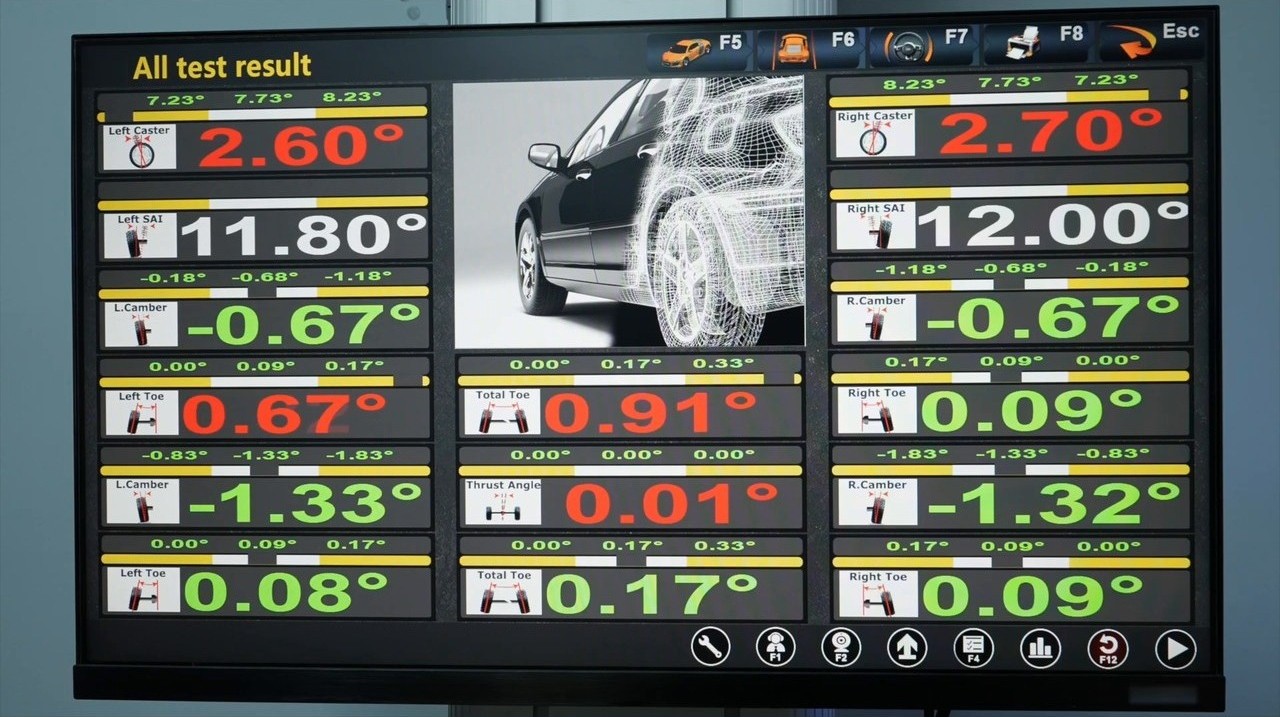
Review the measured camber, caster, toe, thrust angle, and any SAI/kingpin values against the selected reference. Look at relationships, not isolated colors. Front toe can be within tolerance while the steering wheel is not centered. A thrust-angle difference can change how the car tracks. A tire mismatch or worn component can create a road complaint that alignment values alone cannot resolve.
Green normally means the displayed value is inside the selected reference tolerance. It does not prove that the vehicle is straight on the road, that the steering wheel is centered, that both tires match, or that every adjustment has been completed.
Completion check: the technician can state the customer symptom, the measured evidence, a working interpretation, and any unresolved limitation before adjusting anything.
Common mistake: promising the customer a solved pull solely because the screen is green.
Optional measurement: use geometry aids only for the question they answer
The installed XC508 software may include wheelbase or track-width geometry aids. Treat them as optional alignment context, not as a collision-bench measurement system. Use an optional view only when it answers the current job question, and label the result clearly in the work record.
Phase 5 — Adjust, verify, and document
Step 16: Plan the adjustment from OEM data and vehicle condition
Identify which angles are adjustable on this vehicle and how changing one angle may affect another. Use current OEM repair information for target ranges, loading, ride height, tightening torque, and adjustment order. If an adjuster is seized or a component is worn, record the mechanical limitation and repair it instead of forcing a nominal number.
Completion check: the target values, adjustment method, and any repair dependency are written in the job record.
Common mistake: applying a generic “toe and go” sequence to a vehicle that needs a component repair, ride-height check, steering-angle reset, or a manufacturer-specific procedure.
Step 17: Adjust with the steering wheel secured, then remeasure
Keep the steering wheel centered and make the mechanical adjustment in the planned order. Tighten components to the current vehicle specification. After any movement of a clamp, target, plate, steering reference, or suspension component that can affect the result, remeasure the affected stage.
The goal is not a single attractive screenshot. The goal is a stable result that remains inside the correct reference after the hardware is settled and the adjustment fasteners are secured.
Completion check: the recheck is stable, the steering wheel is centered as required, and every remaining out-of-range value has a documented mechanical or procedural limitation.
Common mistake: stopping as soon as the first green screen appears, before tightening and repeating the measurement.
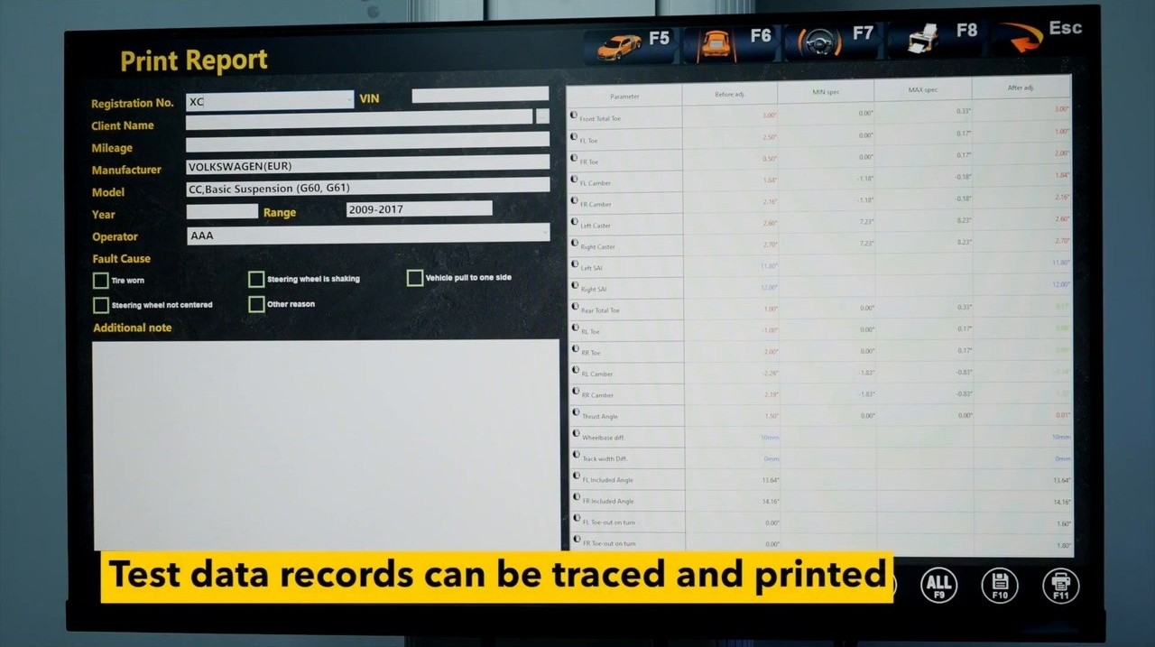
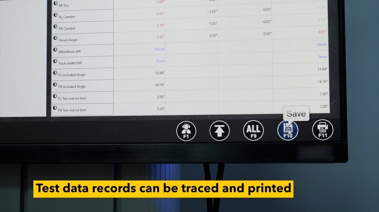
Step 18: Save and print a traceable report
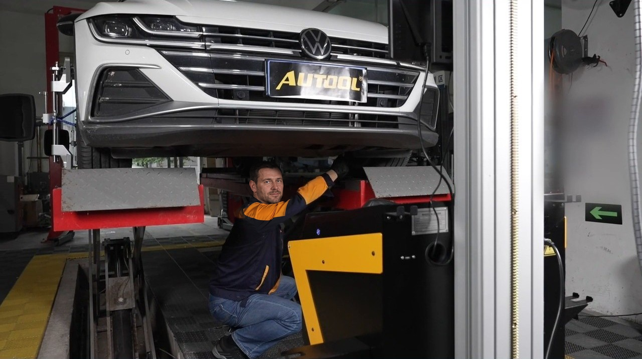
Enter the workshop, operator, and customer information required by your record policy. Save the current measurement and print or export the report. Preserve before/after values, selected vehicle data, date, operator, unresolved defects, and any reason a target could not be reached.
Save the current measurement record before printing or exporting it. If the installed software provides a history view, confirm that the saved job can be reopened; otherwise retain the exported report in the workshop’s normal record system.
Completion check: another technician can identify the vehicle, reference data, measurements, operator, and date from the saved record.
Common mistake: printing only the final chart without preserving the initial condition or the mechanical limitation that explains it.
Phase 6 — Verify the customer outcome and close the job
Step 19: Road-test the original complaint
Perform the road test required by your workshop and vehicle procedure. Confirm steering-wheel center, straight-line tracking, steering feel, noise, vibration, and the customer’s original symptom under safe conditions. If the complaint remains, return to diagnosis rather than declaring success because the values are green.
Some vehicles also have ADAS procedures that depend on the vehicle configuration and the work performed. Do not automatically promise or sell calibration from a generic alignment result. Check the current OEM procedure and record whether calibration is required, not required, or requires further verification.
Completion check: the road-test outcome and any follow-up action are recorded with the report.
Common mistake: road-testing without first confirming that wheels, clamps, plates, and tools have been safely restored for vehicle release.
Step 20: Remove the hardware and shut down safely
Lower and release the vehicle according to the lift SOP. Remove targets and clamps without dropping or dragging them. Return turn-plate locks, rear slip plates, bridge pieces, steering-wheel holders, and brake fixtures to their storage positions. Close the software normally before switching off the main equipment power, protect the camera optics and target surfaces, and leave the bay ready for the next job.
Completion check: the customer vehicle is safely released, the report is recoverable, the targets and cameras are protected, and the bay has no loose hardware or trip hazards.
Common mistake: placing targets face-down on a dirty floor or pulling cables to move the cabinet. Small physical damage becomes a future repeatability problem.
What “finished” means for a four-wheel alignment
Use this final standard instead of asking whether the last screen was green:
- The customer complaint and vehicle identity were recorded.
- Tires, suspension, steering, and adjusters were fit to measure.
- The alignment rack and plates were secure and in the correct state.
- The exact vehicle reference data was selected.
- Four clamps and four targets were correctly installed and readable.
- Rolling compensation was accepted with the steering reference controlled.
- Required angle measurements were completed.
- Adjustments followed current vehicle-specific information.
- Fasteners were secured and the result was rechecked for stability.
- Before/after data was saved in a traceable report.
- The original driving complaint was verified by the required road test.
- The vehicle, equipment, and bay were safely closed out.
Troubleshooting the questions beginners ask most often
A target is red, blocked, or missing. What should I do?
Stop the measurement. Check whether the target is on the correct wheel, the clamp is secure, the target pattern and camera lens are clean, direct sunlight or reflections are affecting the image, and a person, cable, bridge, or body panel is blocking the view. Recheck the target monitor. Do not adjust a vehicle from an invalid image.
The values jump after I touch the hardware. Is the camera broken?
First check the mechanical system: rack movement, plate locks, clamp seating, target stability, wheel restraints, worn suspension, and steering-wheel movement. A changed clamp or target can require a new validity or compensation cycle. Only after the physical causes are excluded should you escalate a camera or calibration concern.
Everything is green, but the vehicle still pulls. Why?
Check tire pressure and matching, road crown, steering-wheel center, thrust angle, suspension damage, tire conicity, and whether the original symptom was caused by something other than alignment. The color expresses the selected reference tolerance; it is not a road-test verdict.
The vehicle is not in the database. Can I choose the closest model?
No. Verify the market, year, drivetrain, suspension, and software/database version. Use documented OEM or authorized user-defined data only when it has been verified for that vehicle. A wrong reference can produce a neat report with the wrong conclusion.
Does the XC508 need to be calibrated every day?
Current official product information says the XC508 targets do not require routine calibration. If the system was moved, the cameras or column were altered, or readings are not repeatable, stop and contact authorized AUTOOL support. Do not copy service settings from another installation.
Can I align a special 24-inch wheel with the standard procedure?
The current official product information states a standard 10–23-inch rim range. Treat 24-inch use as configuration-dependent and confirm it with AUTOOL before accepting the job.
Final answer: how to use the XC508 well
The AUTOOL XC508 is best understood as a guided 3D wheel alignment system inside a complete workshop process. The durable skill is not memorizing where the Next button appears. It is building a valid reference, checking the vehicle before measurement, keeping targets and clamps stable, following compensation and angle-sweep prompts, interpreting geometry with the customer symptom, and proving the final result with a recheck, a report, and a road test.
Treat the AUTOOL XC508, rack, plates, targets, vehicle data, mechanical condition, technician decisions, and road test as one workflow. If any reference is wrong or unstable, correct it before accepting the result. Before ordering, confirm the exact wheel range, rack and bay requirements, power version, database coverage, included clamps and targets, installation terms, training, software support, service access, price, shipping, warranty, and return terms. A product photo or a green sample screen cannot establish fit for your workshop.
Safety, version, and support limits
Use the current XC508 software/help, the exact vehicle data, current OEM repair information, your lift and alignment-rack procedures, and authorized AUTOOL service instructions before performing work. This operating guide has not independently verified measurement accuracy on a real vehicle and cannot replace technician training or a vehicle-specific repair procedure.











Comments 0
Questions, fixes, and real-world diagnostic notes from readers.
Be the first to share a diagnostic result or ask a follow-up question.