
How to Use the MRCARTOOL N150 Articulating Automotive Borescope

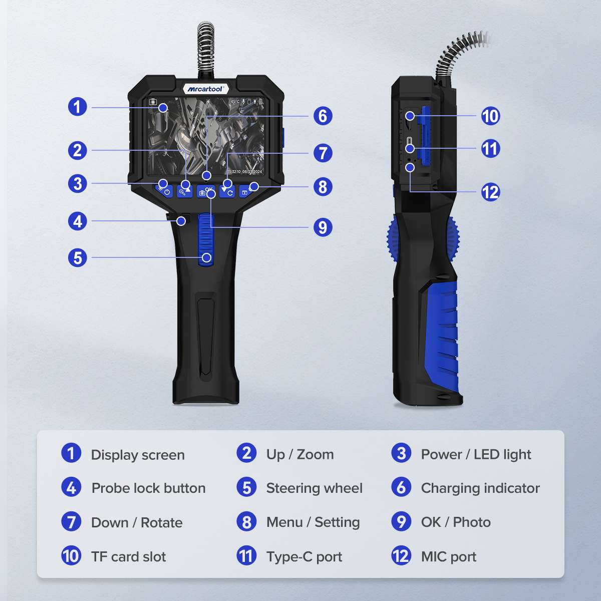
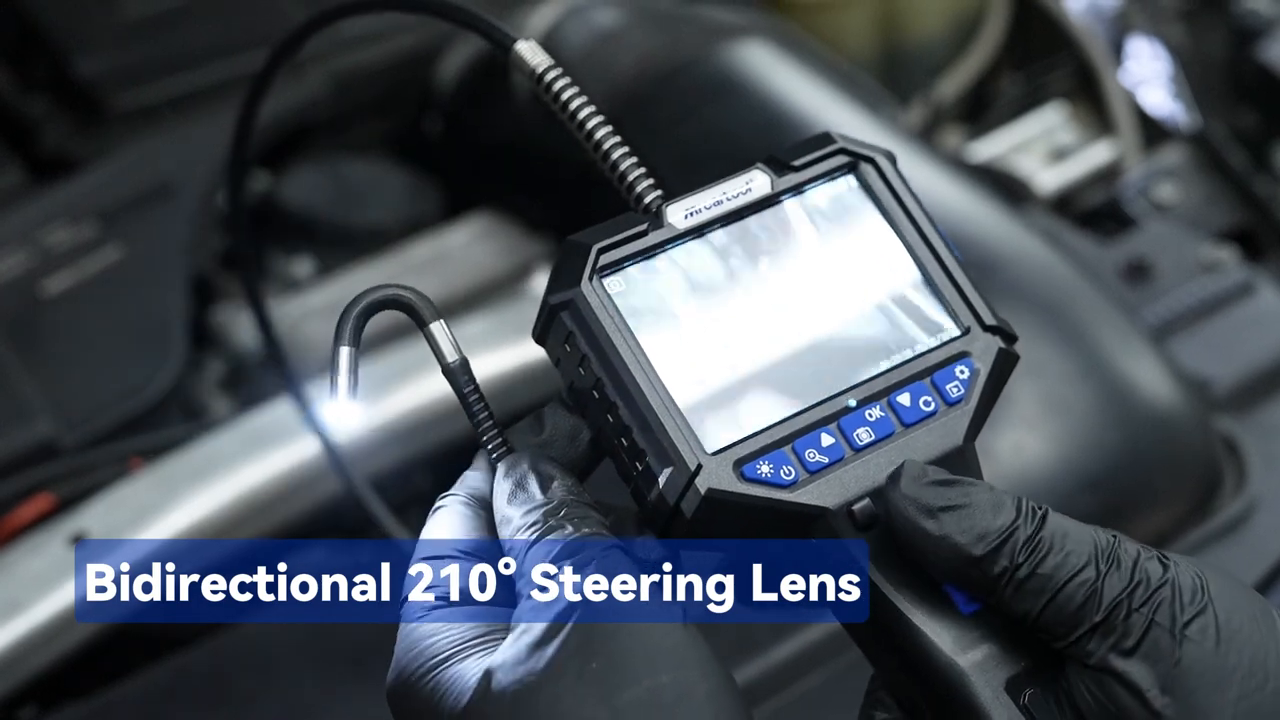
The MRCARTOOL N150 articulating automotive borescope combines a detachable 3.5-inch display with a 6.2 mm camera probe that steers in two directions through approximately 210 degrees. That articulation helps you look back at valve faces, cylinder walls, pipe joints and hidden connectors, but it also creates the tool’s main risk: turning the wheel while the flexible tube is sharply bent can overload the steering wires. The useful method is to plan a clear route, straighten the working section, steer only near the target and record a repeatable view before withdrawing the probe.
Quick answer: Cool and de-energize the area, charge the N150 with the supplied Type-C cable and the adapter specified for your unit, format a TF card if evidence is needed, clean the lens and test the live image in open air. Feed the probe with the articulation centered; never push with the tip already turned. Near the target, make small steering-wheel movements, use the angle lock only after the view is established, set the LED only bright enough to avoid glare, focus from roughly 20–100 mm, record the view, unlock and center the tip, then withdraw slowly.
In this guide
Know the exact N150 limits
The current N150 manual specifies a 3.5-inch IPS display, a 6.2 mm camera head, a one-metre probe, approximately 210-degree two-way articulation and a recommended depth of field of 20–100 mm. The camera uses a one-megapixel sensor with a 90-degree field of view and six LEDs. Photos and video can be stored on a TF card up to 32 GB. The built-in 2200 mAh lithium battery and Type-C connection support portable inspection and file transfer.
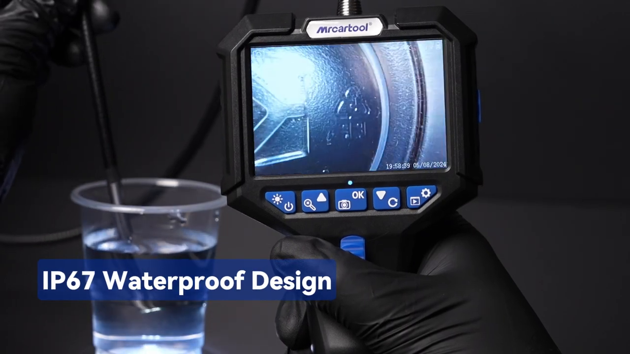
The camera lens is rated IP67; the whole instrument is not waterproof and must not be operated underwater. The manual lists a -10 to 70°C operating range for the flexible tube but only -10 to 50°C for the whole unit. The product media also describes a high-temperature alarm. Treat the display temperature as a warning aid—not permission to insert the probe into a hot engine. Let an engine cool, confirm it is safe to access and keep the screen, connectors and handle away from coolant, fuel, oil and water.
Do not inspect a running engine or energized mechanism. A piston, valve train, fan, belt or electric actuator can trap the probe instantly. Follow the vehicle procedure, isolate the energy source, secure the key and verify that moving parts cannot start before inserting the camera.
What the N150 can—and cannot—tell you
A borescope is a visual evidence tool. It can reveal a wet area, carbon pattern, foreign object, damaged edge, displaced seal or wiring condition where direct sight is impossible. It cannot by itself identify the liquid, measure crack depth, prove compression, confirm electrical continuity or establish the root cause of a failure. Use its images to narrow the next test. For example, an unusual cylinder-wall mark may justify a leak-down test; a wet connector may justify circuit and source tracing; a suspected evaporator leak still needs the specified leak-detection method.
Prepare the vehicle and the borescope
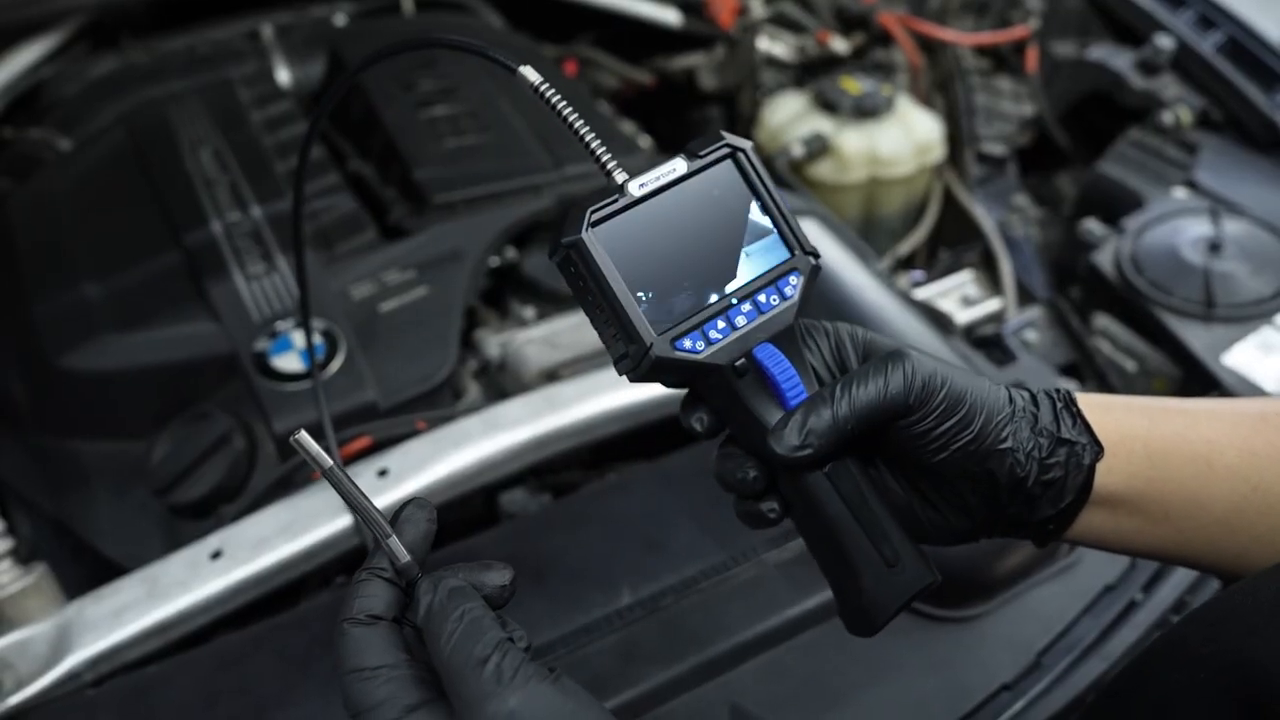
Choose the access point before powering the camera. For a cylinder inspection, note the cylinder number, let the engine cool, disable starting and remove the spark plug according to the service procedure. For an intake, HVAC case, door cavity or wiring route, identify every sharp edge, moving door, fluid pocket and possible exit. Measure the access diameter rather than assuming the 6.2 mm head will clear a fitting. If the head enters but the articulated section or cable jacket catches, retrieval can become harder than insertion.
- Inspect the lens window, protective braid, flexible tube, steering section and connector for cuts, kinks or loose parts.
- Clean the lens with the supplied lint-free cloth; a smear close to the lens can resemble a defect in the inspected surface.
- Charge through the Type-C port with the supplied cable and the adapter specified for the delivered unit; do not improvise a power source.
- Power on in open air, verify a stable image and move the steering wheel gently in both directions, then return it to neutral.
- Set the date and time if the files will support a repair record, and confirm adequate TF-card space before insertion.
- Place removed plugs and fasteners in a controlled tray and protect the access opening from dropped debris.
Set up the display, TF card and LED
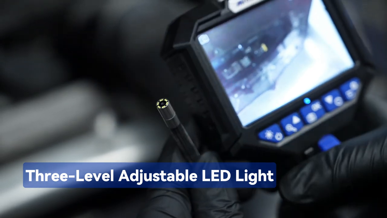
Hold the power button for about two seconds. The N150 starts with its LED at the brightest setting; press the LED/power control briefly to step through brightness levels. Maximum brightness is rarely the clearest setting on shiny piston crowns, wet metal or pale plastic. Begin low, move the tip into the 20–100 mm focus zone and increase the light until edges are defined without a white hotspot. If the view remains milky, withdraw and clean the lens before changing conclusions.
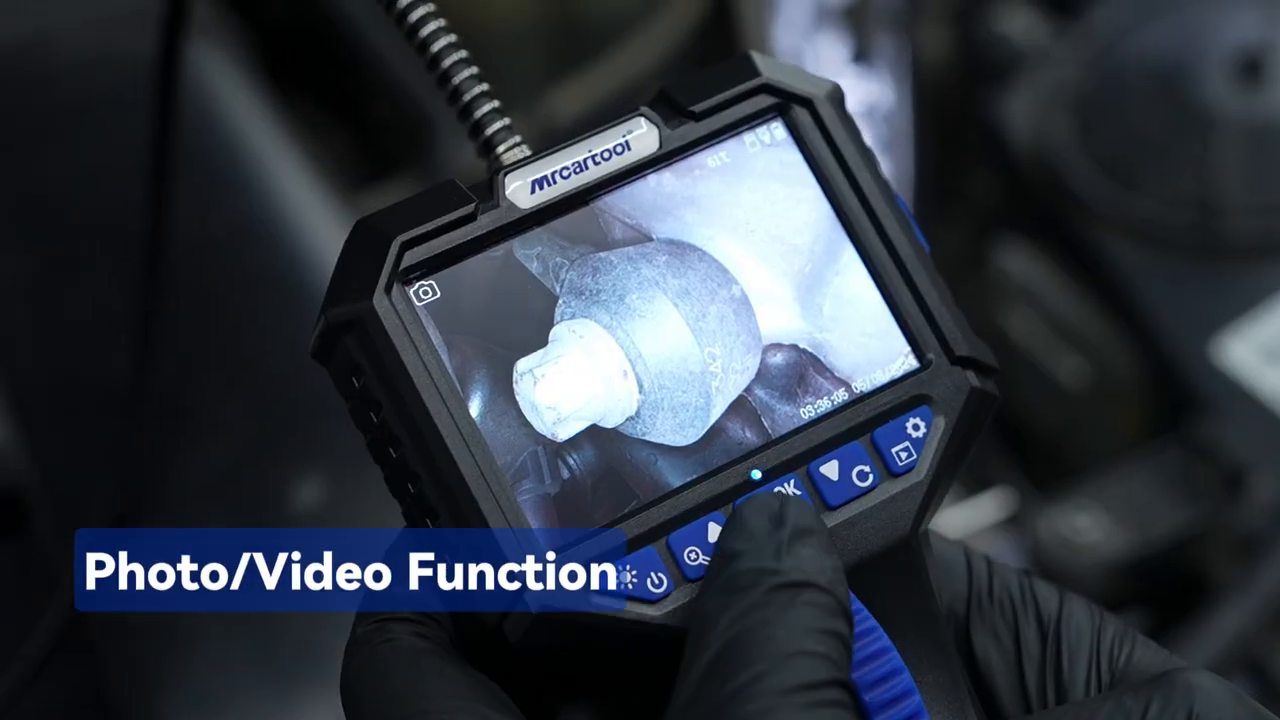
To record, open the rubber cover, insert a compatible TF card until it engages and close the cover. A short press of the photo/OK control captures a JPG; holding it for about two seconds starts video, and pressing again stops it. The display menu also provides image rotation, zoom, playback, protection and deletion. Digital zoom enlarges pixels rather than adding detail, so save an unzoomed context image before using zoom to point out a feature.
Route and steer the probe step by step
1. Establish a neutral insertion path
Straighten the flexible section enough that the articulation mechanism is not loaded, center the steering wheel and hold the cable close to the access point. Feed the probe by advancing the cable—not by pushing on the display or twisting the handle. Watch the live image continuously. If the image spins unexpectedly or the cable buckles, withdraw slightly and correct the route rather than adding force.
2. Build an orientation reference
Before searching for damage, capture a recognizable landmark: spark-plug threads, a valve edge, pipe junction, connector shell or fastener. Note which steering direction moves the image toward that landmark. A borescope view lacks normal depth cues, so this reference prevents the common mistake of describing an unidentifiable close-up as a confirmed defect.
3. Steer only after the tip reaches open space
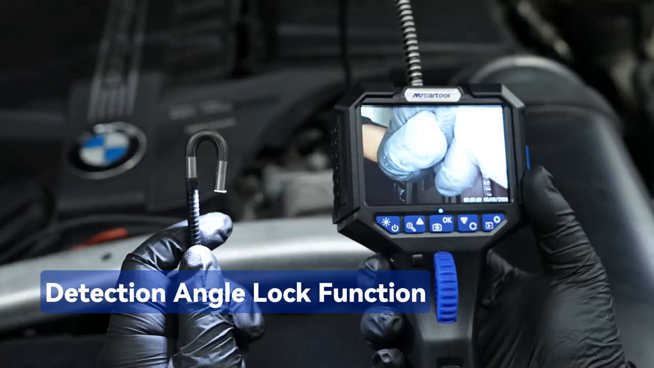
Use small, smooth movements of the steering wheel. Stop as soon as resistance increases, the view stops responding or the tube begins to wind up. Once the view is framed, press the detection-angle lock so the tip stays steady while you inspect or record. Release the lock before changing direction. Never operate the wheel roughly or use the cable as a lever; for a larger change, unlock, return the tip near neutral, withdraw to a wider area and reposition the route.
4. Scan in a repeatable pattern
For a cylinder, start with the piston crown, sweep the circumference, inspect the cylinder wall in overlapping bands and then look toward the valves where the access geometry permits. For a pipe or cavity, inspect one side continuously from entry to destination, then the opposite side on withdrawal. Pause at every joint and low point where residue collects. This systematic pattern is faster than chasing each interesting reflection and makes a second inspection comparable.
Capture evidence that another person can understand
Use a three-image sequence: an overview that identifies the location, a medium view that shows the feature relative to a landmark and a close view within the focus range. Record a short video only when movement, continuity of a route or the relationship between surfaces matters. Hold the probe still for two seconds before and after the important view; constant steering produces footage that is hard to interpret.
Review the files before dismantled parts are restored. Reject images blurred by motion, lens contamination or overexposure. If a mark changes when the light or angle changes, it may be a reflection. If residue moves after the probe touches it, record that fact rather than labelling it as a crack or fixed deposit. Name or log the vehicle, inspection point, orientation, date, operating condition and related test result outside the image file so the evidence remains traceable.
Return the camera to neutral and retrieve it
Before withdrawal, reduce articulation until the tip is as straight as the route allows. Pull with slow, even motion while watching both the access point and display. If the probe catches, stop immediately. Advance a few millimetres, neutralize the steering wheel and change the cable angle; do not jerk the braid over a sharp edge. Count any adapters or protective parts used and confirm that the probe head and cable are intact as soon as they clear the opening.
Power off by holding the button for about two seconds. Wipe the camera head and cable with a suitable non-abrasive cloth, keeping liquid out of the handle, display, TF-card slot and Type-C connection. The IP67 statement applies to the lens assembly, not the whole device. Let the probe dry, leave it unarticulated and store it in a broad coil without a tight bend. Copy important files before formatting the card.
Troubleshooting
| Problem | Check first |
|---|---|
| Image is dark | LED level, lens cleanliness, connector seating and whether the tip is blocked by the access wall |
| Image is white or hazy | Lower LED brightness, increase the 20–100 mm working distance and clean oil or condensation from the lens |
| Steering wheel feels stiff | Release the angle lock, stop, straighten or unload the tube, neutralize the tip and withdraw—never force the wheel |
| Photo or video will not save | TF card insertion, capacity and free space; back up files before formatting the card |
| No power or charging | Supplied Type-C cable, specified adapter, charging port cleanliness and battery state |
| Unexpected temperature warning | Withdraw from the hot area and allow full cooling; the manual states shutdown at 90°C, which is protection rather than a working target |
| Possible defect looks different on repeat | Clean lens, repeat the angle and light level, include a landmark and corroborate with the appropriate mechanical test |
Frequently asked questions
Can I inspect a cylinder immediately after shutting off the engine?
No. The product guidance recommends waiting for the engine to cool, and the whole unit has a lower operating limit than the flexible tube. Isolate the starting system and verify a safe temperature before insertion.
Can I bend the probe by hand to look sideways?
No. The camera direction is controlled by the steering wheel. External force on the articulated tip or turning the wheel while the hose is tightly bent can deform or break the traction mechanism.
Is the entire N150 waterproof?
No. The camera lens is rated IP67, while the complete instrument is explicitly not waterproof and must not be used underwater. Keep the display, handle and open ports dry.
What is the best focus distance?
The exact N150 manual gives a depth of field of 20–100 mm. Move the tip rather than relying on digital zoom, and reduce LED glare on reflective surfaces.
Can a borescope image confirm a failed engine part?
It can document a visible condition, but diagnosis usually needs corroboration such as compression, leak-down, electrical, pressure, fluid or dimensional testing. Record what is visible without overstating the cause.
Final N150 checklist
- Vehicle cool, de-energized and protected against unexpected movement
- 6.2 mm access and complete retrieval route confirmed
- Lens, braid, tube and articulation checked in open air
- Supplied Type-C cable and specified adapter; TF card and date/time confirmed
- Probe inserted neutral and steered only in open space
- LED adjusted for detail rather than maximum brightness
- Overview, landmark view and focused close view captured
- Tip returned toward neutral before slow withdrawal
- Probe intact, cleaned, dry and stored in a broad coil
- Visual finding linked to the next diagnostic test
If the labels, screen connection, supplied accessories or menu on your delivered unit differ, use the exact PDF available from the MRCARTOOL manual download page before operating it.
A successful N150 inspection is not the deepest insertion or the sharpest-looking close-up. It is a controlled route that can be reversed, a view tied to a known landmark and a finding that another technician can verify. Prepare the access, steer gently near the target, control glare, capture context and neutralize the probe before withdrawal. Those habits protect the articulation mechanism and turn a hidden-space image into useful repair evidence.











Comments 0
Questions, fixes, and real-world diagnostic notes from readers.
Be the first to share a diagnostic result or ask a follow-up question.