Fuel Pressure Looks Normal at Idle but the Engine Falls Flat Under Load? Replay Demand

Pressure Under Load
A plausible fuel-pressure reading at idle proves only that the system met a low-demand condition at one moment. During acceleration, injector on-time, airflow, pump demand, electrical load, boost, and rail targets can change quickly. The diagnosis must replay that demand and watch whether pressure, volume, electrical supply, and commanded values keep pace.
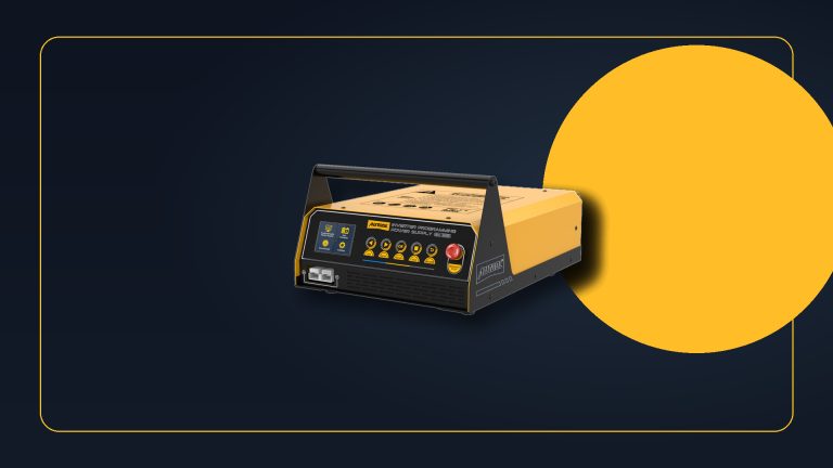
For a conventional port-injected low-pressure system, a safely connected gauge can expose the drop that an idle snapshot misses. The AUTOOL PT635 digital fuel-pressure gauge kit is one route for watching low-side pressure through idle and load. It is not a direct-injection high-pressure rail tool, so first identify the circuit and confirm that every fitting, hose, and gauge is rated for it.
Fuel is flammable and pressurized. Relieve pressure, ventilate, control spills, eliminate ignition sources, wear eye protection, and never improvise an under-hood road-test setup with an unsecured gauge or hose.
Quick answer: An idle pressure reading proves only one low-demand moment. Reproduce the loss of power safely, record pressure through the event, correlate it with mixture and pump-command evidence, and separate supply, control, restriction, regulator and injector branches before replacing parts.
In this guide
- Define exactly where power falls away
- Rule out non-fuel limits before opening the system
- Choose the correct low- or high-pressure circuit
- Recreate demand while watching pressure
- Add volume, voltage, current, and scan-data context
- Separate supply, control, injector, and mechanical branches
- Compare dynamic fuel-test routes
- Repeat the same load after repair
Define exactly where power falls away
Write the complaint by engine state: hot or cold, throttle angle, rpm, boost, gear, road grade, fuel level, and duration. “Falls flat” may mean lean hesitation, ignition breakup, throttle closure, exhaust restriction, knock control, transmission intervention, boost control, or a fuel-supply limit. Record DTCs, freeze frame, fuel trims, misfire data, desired and actual rail pressure where available, throttle command, airflow, oxygen-sensor response, and battery voltage.
Do not begin with a gauge if the data already shows deliberate throttle closure, rev limiting, torque management, or a transmission event. Likewise, an ignition failure under cylinder pressure can feel exactly like fuel starvation. The first task is to define a repeatable corridor where the symptom occurs.
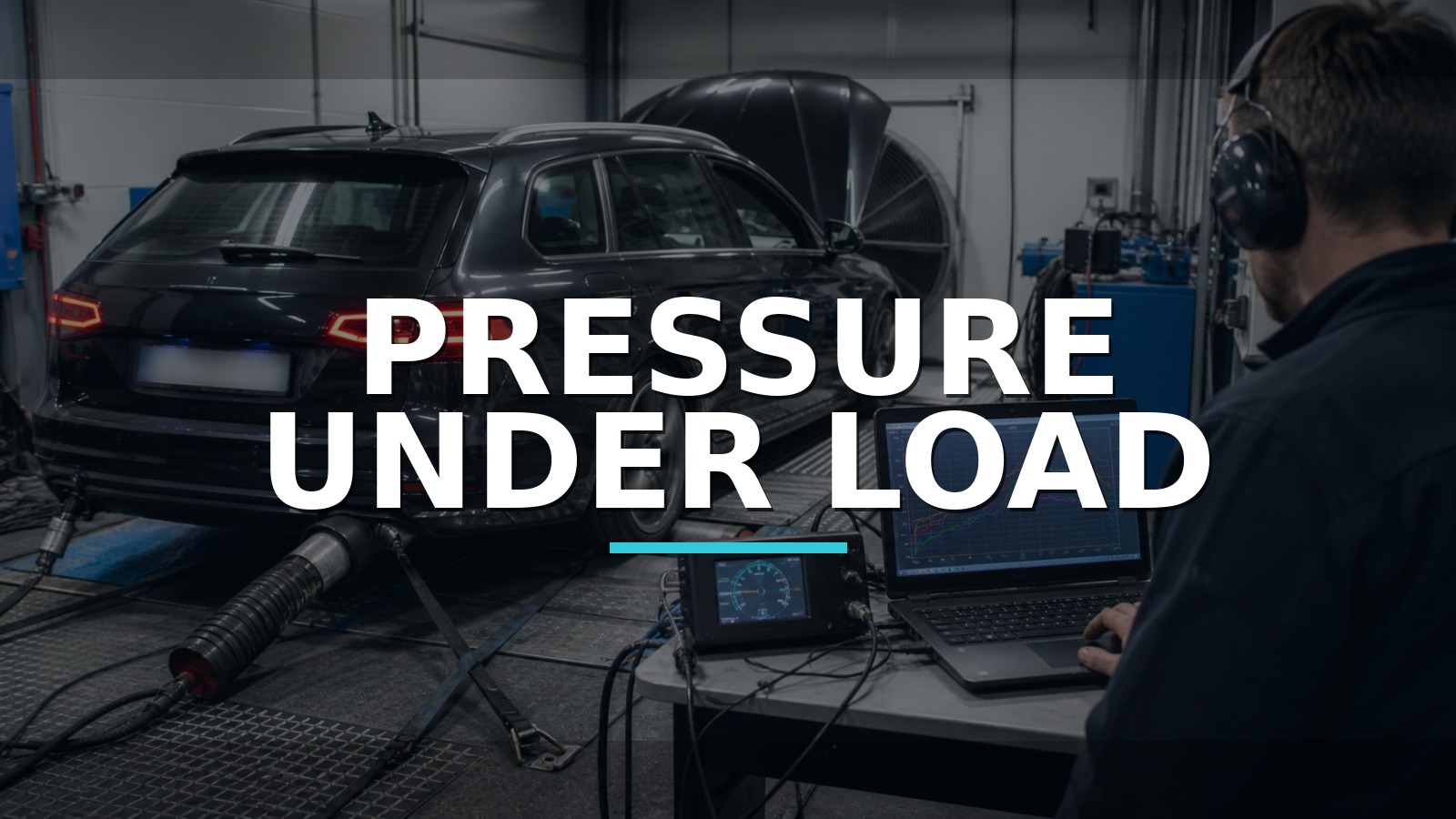
Use a safe stationary test only if the manufacturer allows it. Many faults require road load or a dynamometer. A second technician or data logger should handle readings; the driver watches the road.
Rule out non-fuel limits before opening the system
Inspect air intake, charge hoses, exhaust, ignition components, wiring, and recent work. Verify that the engine reaches full commanded throttle where expected and that no protection strategy is active. Compare short- and long-term fuel trims at idle and under controlled load. Positive trim under load can support insufficient fuel, but unmetered air, exhaust leaks, biased airflow measurement, or oxygen-sensor faults remain possible.
Look at misfire distribution. One cylinder failing points more strongly toward injector, ignition, compression, or local air issues; all cylinders leaning together supports a shared supply or measurement problem. Check battery and charging voltage because a pump that receives inadequate voltage may hold idle pressure and fail at high demand.
Only open the fuel system when pressure evidence can separate the remaining hypotheses. Repeated gauge connection is not risk-free.
Choose the correct low- or high-pressure circuit
Port injection generally uses a low-pressure supply that may be accessible at a service port or approved adapter. Gasoline direct injection adds a mechanically driven high-pressure circuit whose pressure and hazards are far beyond ordinary hose-and-gauge tools. Some systems have both a low-side feed and a high-side rail sensor; diagnose them as related but separate stages.
Consult the exact service information for depressurization, connection, pressure range, adapter, key-on priming, idle specification, residual test, and load test. Inspect seals and hoses before every use. Secure the PT635 or another low-pressure gauge where it can be observed without contacting heat or moving parts, and perform only the approved stationary procedure. Use scan logging or a rated remote transducer for road/dyno work.
On GDI, begin with low-side volume/pressure, pump supply, commanded versus actual high-side pressure, and manufacturer test routines. Never loosen a high-pressure fitting on a running or recently stopped engine unless the service procedure has made the system safe.
Recreate demand while watching pressure
Record pressure at key-on prime, idle, specified snap or loaded condition, and after shutdown if residual behavior is relevant. Pair every number with rpm, load, battery voltage, and symptom. A minimum-reading function can be useful, but it must be captured during the exact event and not during shutdown or connection disturbance.
Interpret patterns conditionally:
| Pattern | Strong branch | What still needs proof |
|---|---|---|
| Pressure drops as load rises | Supply volume, pump voltage/current, restriction, control | Which part of the supply path fails |
| Pressure stable, trims go lean | Injector delivery, unmetered air, sensor bias, exhaust evidence | Independent airflow and cylinder evidence |
| Desired high-side rises, actual does not | Low-side feed, high-pressure pump/control, leakage | Exact GDI procedure and rated tools |
| Pressure overshoots or oscillates | Regulator/control/return behavior | Command, electrical, and mechanical correlation |
A single snap-throttle event in neutral may not consume enough fuel to reproduce a road-load failure. Do not “prove” a system from a test that never entered the complaint corridor.
Add volume, voltage, current, and scan-data context
Pressure is resistance to flow, not the same as delivered volume. A restricted filter or weak pump can build normal pressure against low demand, then fail to supply volume. Perform the manufacturer’s volume or delivery test with approved collection, time, and fire precautions. Returnless and variable-speed systems may require command control rather than a simple flow diversion.
Measure pump voltage and ground under load. Voltage drop across a relay, connector, ground, control module, or wiring can starve the pump. A current clamp and waveform may reveal pump commutation or changing load, but waveform interpretation should support—not replace—pressure and volume evidence.
Compare commanded and actual pressure, pump duty, low-side sensor, high-side rail sensor, trims, and oxygen response on one time axis if the platform permits. ECU data is the controller’s view. An independent low-side gauge can expose a biased sensor, but both must be recorded under the same state.
Separate supply, control, injector, and mechanical branches
If low-side pressure and volume fall with correct pump voltage, suspect pump, pickup, tank restriction, or in-tank leakage. If pump voltage falls, trace power, ground, relay, driver, and command. If pressure remains correct but mixture goes lean across all cylinders, verify injector command and total delivery, intake/exhaust evidence, and sensor accuracy.
For one-cylinder symptoms, use balance testing, electrical current, injector bench work, compression, and ignition checks as appropriate. Do not raise system pressure to compensate for a weak injector. For a GDI system, prove low-side supply before condemning the high-pressure pump, and follow exact desired-versus-actual tests.
Contaminated fuel, incorrect fuel, tank venting, and faults that appear only below a certain fuel level can imitate pump weakness. Record level and refueling history so the case does not lose its environmental clues.
Compare dynamic fuel-test routes
OTC, Mityvac, Innova, and CTA provide familiar analog pressure-kit routes. Pico’s WPS500X route adds high-speed recording and correlation where its range and adapters suit the circuit. PT635 fits the middle when the shop wants a digital low-pressure reading, temperature, extrema, and a broad adapter set without building a full scope setup. There is no defensible audited model-level market-share dataset for these kits.
Choose the complete method, not the longest adapter list. Confirm range, hose rating, serviceable seals, exact adapter, remote observation, replacement parts, and fluid compatibility. If the work is mostly direct-injection high-pressure diagnosis, buy the correct rated GDI route instead of treating a low-pressure kit as universal. If load reproduction requires a dynamometer and protected measurement, outsourcing is the safe value choice.
Repeat the same load after repair
After the supported repair, replace disturbed seals, torque fittings, restore clips and covers, prime as specified, and inspect for leakage before starting. Remove every temporary gauge and confirm the service port is capped. Clear adaptations only when the repair procedure requires it.
Repeat the original temperature, gear, rpm, throttle, grade or dynamometer load, and fuel level as closely as practical. Confirm stable desired-versus-actual behavior, pressure that remains within the exact specification, normal trims and oxygen response, no misfire, and no leak. The best conclusion connects cause to demand: the system held idle pressure, failed volume under load because the proven supply path lost output, and now maintains both pressure and performance in the same corridor. That is much stronger than “fuel pressure was normal.”