
A/C High-Side Pressure Spikes at Idle? Start with Heat Rejection, Not Refrigerant Guessing

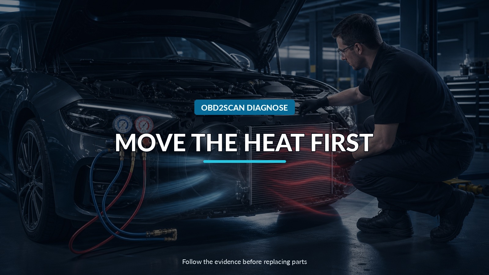
Move The Heat First
High-side A/C pressure that climbs mainly at idle is often a heat-rejection clue. At road speed, ram air may carry heat through the condenser even if a fan is weak, airflow is recirculating, fins are blocked, or hot radiator air cannot leave the engine bay. At idle those weaknesses become visible. Measure air and temperature before treating the pressure gauge as a refrigerant quantity meter.
The missing capability is simultaneous pressure and line-temperature observation while operating conditions are controlled. A digital manifold such as the MRCARTOOL L205 refrigerant manifold is one route for seeing both sides and temperature relationships on a correctly identified compatible refrigerant. It does not recover refrigerant, measure charge mass, prove airflow, or authorize service by pressure alone.
Automotive refrigerant service requires identification, legal recovery equipment, correct oil and refrigerant handling, protective equipment, and high-voltage precautions where applicable. High-side pressure can become dangerous. Stop the test if pressure, temperature, noise, hose condition, or manufacturer limits require it.
Quick answer: Reproduce the idle-only condition, verify condenser airflow and every fan stage, compare refrigerant pressures with line and air temperatures, and confirm heat rejection before considering charge quantity or metering faults.
In this guide
- Capture the idle-only thermal condition
- Prove the condenser can move air
- Measure temperatures before interpreting pressures
- Compare idle and controlled raised speed
- Separate heat rejection from charge and restriction
- Use the manifold as a relationship tool
- Keep refrigerant handling professional
- Verify in the same ambient condition
Capture the idle-only thermal condition
Record ambient dry-bulb temperature, humidity if relevant, sun load, vehicle heat soak, engine temperature, engine speed, cabin settings, recirculation state, blower speed, doors or windows, vent temperature, and the time since A/C engagement. Note whether pressure rises immediately or only after several minutes.
Compare cold start, stabilized idle, and the exact condition where the complaint begins. If cooling improves when the car moves, record road speed or controlled fan airflow without turning that observation into a diagnosis. If the pressure spike appears after engine coolant temperature rises, the radiator fan strategy and shared heat stack become especially important.
Scan HVAC, engine, fan, hybrid, and body modules. Save refrigerant-pressure sensor data, fan command and feedback, compressor command or speed, clutch state, coolant temperature, ambient sensor, evaporator temperature, air-door position, and codes. Mechanical manifold readings and electronic sensor values should be compared, not assumed identical.
Prove the condenser can move air
Inspect the condenser face for debris, folded fins, corrosion, impact damage, missing air guides, blocked grilles, and aftermarket accessories. Look between the condenser and radiator. DENSO’s service bulletin specifically calls out dirt accumulating in that hidden gap and explains that restricted airflow raises condensing pressure.
Verify every fan, direction of rotation, speed stage, shroud, seal, relay, controller, fuse, power supply, ground, and command. A fan can spin but move too little air because it is slow, reversed, damaged, missing a shroud, or pulling recirculated hot air around a gap. Compare command with current draw, voltage, speed feedback, and measured airflow where the procedure supports it.
Confirm that hot engine-bay air can leave. Bent supports, missing undertrays, incorrect body panels, or packed radiator fins can reduce mass flow even with a working fan. Water sprayed on a condenser may lower pressure, but it changes heat transfer and is not a stand-alone diagnostic verdict.
Measure temperatures before interpreting pressures
DENSO describes the condenser as the heat exchanger that releases cabin heat to outside air and changes high-pressure refrigerant vapor toward liquid. Observe the temperature entering and leaving the condenser, not just the gauge. Use contact probes properly attached and insulated where required; an infrared reading on shiny tubing can be misleading.
Record high-side line temperature, low-side line temperature, vent temperature, air temperature entering the condenser, and air leaving it. For systems and refrigerants where the method applies, calculate or read subcooling and superheat according to the manufacturer’s procedure. Variable compressors and electronically controlled expansion devices may not behave like fixed-displacement textbook examples.
Pressure must be paired with temperature and refrigerant identity. A stored refrigerant database is convenient, but it cannot identify an unknown or contaminated charge. Use an approved identifier before recovery or charging.
Compare idle and controlled raised speed
Hold cabin and ambient conditions as stable as possible. Record both pressures, line temperatures, vent temperature, fan state, and compressor command at idle. Then use only the manufacturer’s approved raised-speed point and time. Do not race the engine to force a result.
If high-side pressure drops and cooling improves as fan airflow or controlled engine speed increases, heat rejection deserves priority. Determine whether the change came from fan speed, compressor speed, pump speed on a hybrid thermal loop, or airflow through the condenser. Several variables can move together.
If pressure remains high despite verified heat rejection, investigate overcharge, noncondensable gas, condenser internal restriction, hose restriction, incorrect refrigerant or oil, expansion-device behavior, and compressor control. If high-side pressure is low with poor cooling, a different branch applies.
Separate heat rejection from charge and restriction
Use a relationship table rather than a single “high” label:
| Evidence pattern | Stronger branch | Required next proof |
|---|---|---|
| High side rises at idle; fan airflow is weak; road-speed cooling improves | condenser airflow/heat rejection | fan circuit and airflow repair, then repeat |
| High side stays abnormal with verified airflow; charge history unknown | charge, contamination, noncondensables | recover, identify, measure, evacuate, recharge by specification |
| Temperature changes abruptly across a small condenser or line zone | restriction | exact temperature/pressure and component procedure |
| Electronic pressure and manifold disagree materially | sensor, service connection, tool accuracy | independent comparison and circuit test |
An overcharged system and poor airflow can coexist. So can a weak fan and restricted condenser. Correct the first proven fault, restore known charge by mass if the circuit was opened, and retest before authorizing another component.
Do not diagnose “too much refrigerant” by bleeding charge until pressure falls. That is inaccurate, environmentally harmful, and often illegal. Recover and weigh the refrigerant with approved equipment.
Use the manifold as a relationship tool
Fieldpiece SMAN, Testo 557s, Yellow Jacket TITANMAX, CPS BlackMax, Mastercool, and MRCARTOOL L205 represent different digital-manifold routes. Professional ecosystems can add wireless probes, logging, vacuum instruments, and job records. A simpler stand-alone manifold may answer an occasional pressure/temperature question.
Choose by refrigerant support, pressure rating, hose and coupler quality, temperature-probe accuracy, serviceability, logging need, and local support. Do not choose by the longest refrigerant list alone. Automotive systems still require the correct service ports, identifier, recovery machine, vacuum equipment, scale, and legal training.
L205 belongs in the diagnostic flow when direct low/high pressure and line-temperature relationships are missing. It should not become a product detour or a substitute for a fan-current test, airflow observation, or measured charge.
Keep refrigerant handling professional
Inspect hoses before every connection and keep them away from fans, belts, and hot exhaust. Wear eye and skin protection. Liquid refrigerant can cause frost injury. Hybrid and electric vehicles may use electrically driven compressors and oils whose contamination can compromise high-voltage insulation.
Follow exact valve sequence, recovery, evacuation, leak testing, oil balancing, and charging by mass. Do not mix refrigerants or introduce air. If pressure rises rapidly beyond the expected service window, disengage safely and investigate rather than waiting for a relief event.
Verify in the same ambient condition
After the supported repair, clean the condenser and radiator correctly, restore foam seals, shrouds, panels, connectors, and fan control. If the refrigerant circuit was opened, leak-test, evacuate, and charge by the exact specified mass and oil procedure.
Repeat the original ambient and heat-soak condition as closely as practical. Log pressure, line and vent temperatures, fan command and response, compressor behavior, engine temperature, and idle versus controlled raised speed. Confirm stable cooling without abnormal pressure cycling or new codes.
The finished diagnosis should explain how heat moved. “Pressure went down after adding refrigerant” is not a valid close. “The commanded fan failed to reach speed, condenser airflow was restored, and the same idle heat load now maintains the expected pressure-temperature relationship” is evidence.





Comments 0
Questions, fixes, and real-world diagnostic notes from readers.
Be the first to share a diagnostic result or ask a follow-up question.