
Oil Cap Whistles and Idle Changes? Measure Crankcase Pressure Before Blaming the PCV Valve

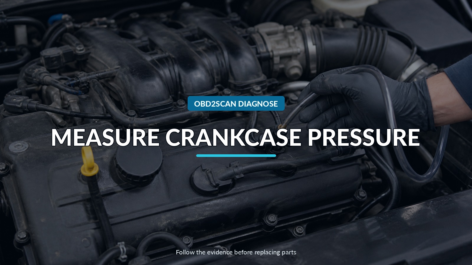
Measure Crankcase Pressure
An oil cap that whistles, resists removal, or changes the idle is evidence that opening the crankcase changed an air path. It is not a universal PCV test and it does not identify a failed valve. Some engines normally maintain slight crankcase vacuum; others use more complex load-dependent routing. The correct question is how pressure behaves with the system intact.
That question calls for a low-range pressure measurement at a defined port and operating state. The AUTOOL PT530 differential pressure manometer is one way to quantify crankcase or vacuum pressure instead of judging a glove or plastic bag. It cannot provide the vehicle’s specification, locate the failed passage, or turn unregulated smoke and pressure into a safe test.
Map the system in four states: engine off, stable idle, the manufacturer-specified raised-load condition, and the transition after a controlled change. Pressure direction, magnitude and response together are more useful than the dramatic moment the cap lifts.
Quick answer: An oil-cap whistle proves an air-path change, not a failed PCV valve. Map the ventilation architecture and measure crankcase pressure at specified states before isolating excessive vacuum, positive pressure, leaks, restriction, or blow-by.
In this guide
Retire the plastic-bag verdict
A bag, glove or sheet of paper may show that gas is moving, but it adds unknown restriction and has no calibrated scale. The oil cap can be hard to lift because of vacuum, a swollen seal, heat or mechanical fit. Idle may change simply because removing it creates an air leak the control system was not designed to meter.
Do not call strong cap suction normal or failed from memory. Vehicle designs differ, and the correct measurement may be in pressure units small enough that a general boost or compression gauge cannot resolve them. Obtain current service information, including test location, engine temperature, accessories, rpm and acceptable range.
Before connecting anything, confirm oil level, correct cap and dipstick seals, hose routing, recent repairs and whether the engine is turbocharged. Look for collapsed hoses, loose fittings, oil leaks, sludge, a damaged diaphragm housing and audible whistle location.
Name the ventilation architecture
Draw the flow path. At idle, manifold vacuum may pull blow-by gases through a regulating path while filtered makeup air enters elsewhere. Under boost or high load, check valves and alternate routes may send gases toward a turbo inlet. Naturally aspirated, turbocharged and valved-cover-integrated systems can respond differently.
Identify each valve, separator, fresh-air line, manifold line and turbo-inlet line. Mark which direction its check valve should allow. If a vacuum pump or unusual crankcase management system is fitted, use its service description rather than a generic PCV diagram.
This map prevents a common error: replacing the most visible valve when the actual restriction is a frozen separator, collapsed hose, blocked drain, wrong cover, intake leak or excessive blow-by overwhelming a healthy system.
Create four pressure states
Connect the manometer with an adapter that seals without restricting the intended test. Route hoses away from belts, fans and exhaust. Zero the instrument as instructed and confirm units. Avoid pushing a long hose into moving engine parts or allowing condensed oil to flood the sensor.
Record:
| State | What to capture |
|---|---|
| engine off | zero stability and trapped pressure after shutdown |
| warm stable idle | crankcase pressure, rpm, trims and whistle |
| specified raised load | pressure response as routing changes |
| controlled opening or pinch only if approved | direction and speed of response |
Do not pinch hoses that are not approved for that test. A blocked crankcase path can build pressure quickly and force oil past seals. Never introduce shop air into the crankcase as a casual leak check.
Read excessive vacuum
Vacuum beyond the model’s specified range can point toward a regulator or diaphragm that admits too much manifold vacuum, a restricted fresh-air path, incorrect plumbing or a valve stuck in the wrong state. Symptoms can include whistling, rough idle, mixture correction, oil pulled into the intake and difficult cap removal.
Correlate the pressure with fuel trims and rpm, but do not treat one trim sign as universal. The engine controller may compensate differently, and other intake leaks can exist. Listen at the cover, hoses and rear main area. Inspect the intake path for fresh oil while recognizing that some oil film is normal in many ventilation systems.
If opening the cap moves pressure toward atmospheric and the idle changes, that confirms interaction. It still does not locate the fault. Isolate the fresh-air and regulated paths only by the manufacturer’s procedure and watch which change restores the expected pressure.
Read positive pressure
Positive crankcase pressure can result from a blocked outlet, frozen separator, kinked hose, failed check valve, excessive blow-by, wrong connection or a system that cannot handle the operating condition. It may drive oil through gaskets and seals or push the dipstick upward.
Inspect for sludge and ice, particularly after short trips or cold weather. Verify drains and separator paths. If pressure rises mainly with load, compare the boost-side route and check-valve operation. If it is high at idle too, a restriction or excessive cylinder leakage deserves attention.
Compression and leak-down tests answer different questions from a crankcase manometer. They may help identify cylinder sealing loss, but a normal static result does not automatically validate every dynamic blow-by condition. Use the engine maker’s test and compare cylinders and operating state.
Use smoke only on a defined safe boundary
Smoke can help reveal a leaking hose, cover joint or intake connection, but first define whether the tested path is the intake side, fresh-air side or an isolated component. Depressurize it and use only the permitted low pressure and fluid. Protect sensors, turbocharger paths and delicate diaphragms.
A visible leak from a cover seam may explain unmetered air, oil leakage or pressure loss, but it does not prove the regulator itself failed. Conversely, no external smoke does not rule out an internally torn diaphragm that leaks between passages.
Do not smoke the complete crankcase at a machine’s default output without confirming the allowed pressure. Some smoke devices produce more pressure than seals or ventilation diaphragms should see. A regulated supply, separate pressure observation and service information control the test.
Follow the state that fails
If pressure is wrong only at idle, focus on the manifold-vacuum regulation path and fresh-air balance. If it fails under boost/load, focus on alternate routing, check valves and restrictions. If it remains positive in all states, check obstruction and blow-by. If pressure is correct but the whistle remains, locate an intake, turbo, gasket or bearing-related sound instead of replacing PCV parts by association.
Confirm software or updated-component information for the exact engine. Integrated valve covers, external valves and hose assemblies may have revisions. Compare replacement routing and part application; a visually similar valve can have a different calibration.
After repair, clean oil residue only as needed so new leakage can be seen. Do not assume that a new cover automatically fixed downstream oil saturation, blocked intercooler drains or damaged seals.
Verify pressure and oil behavior together
Repeat all recorded states at the same temperature and accessory load. Pressure should fall within the vehicle’s specified behavior, recover consistently during transitions, and remain stable without new whistles, rough idle or abnormal trims.
Recheck oil level and leakage after a controlled drive. Watch for oil in intake paths, smoke, consumption and seal areas over an appropriate interval. A seal already damaged by pressure may continue leaking after the ventilation cause is corrected.
The diagnosis is complete when the pressure map—not the feel of the oil cap—matches the system design and the related symptom stays gone. The cap was a clue that opened the case; the measured states are what close it.






Comments 0
Questions, fixes, and real-world diagnostic notes from readers.
Be the first to share a diagnostic result or ask a follow-up question.