
A Shiny Piston Crown on a Borescope: Coolant Wash, Fuel Wash, or Normal?

Describe Before You Diagnose
The useful borescope note is not “bad piston.” It is “cylinder three looks cleaner and wetter than cylinders two and four when photographed with the same lens angle, light, and piston position.” A picture records reflected light from a surface; coolant wash, fuel wash, oil, carbon pattern, recent running, cleaner residue, and normal cylinder-to-cylinder variation can overlap visually.
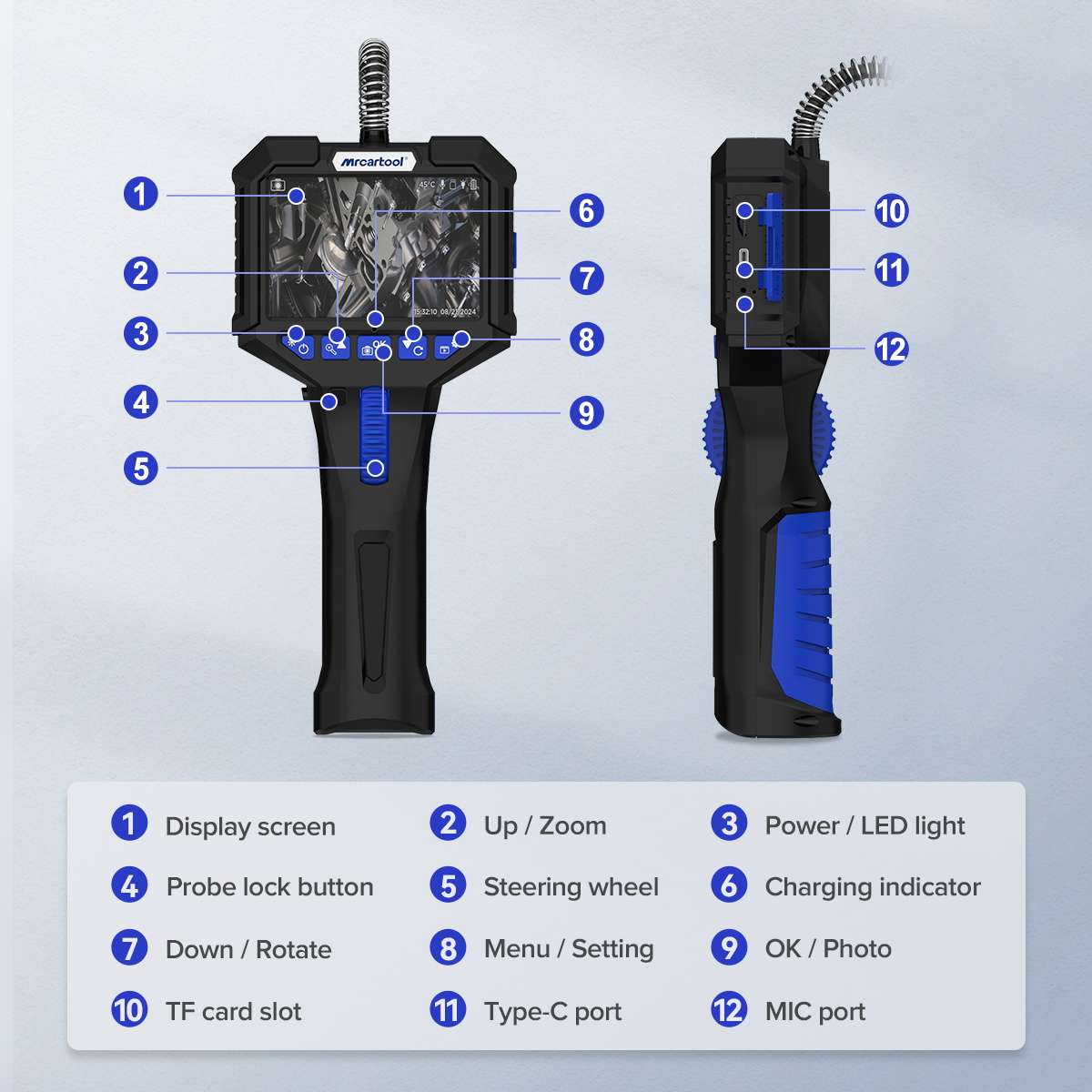
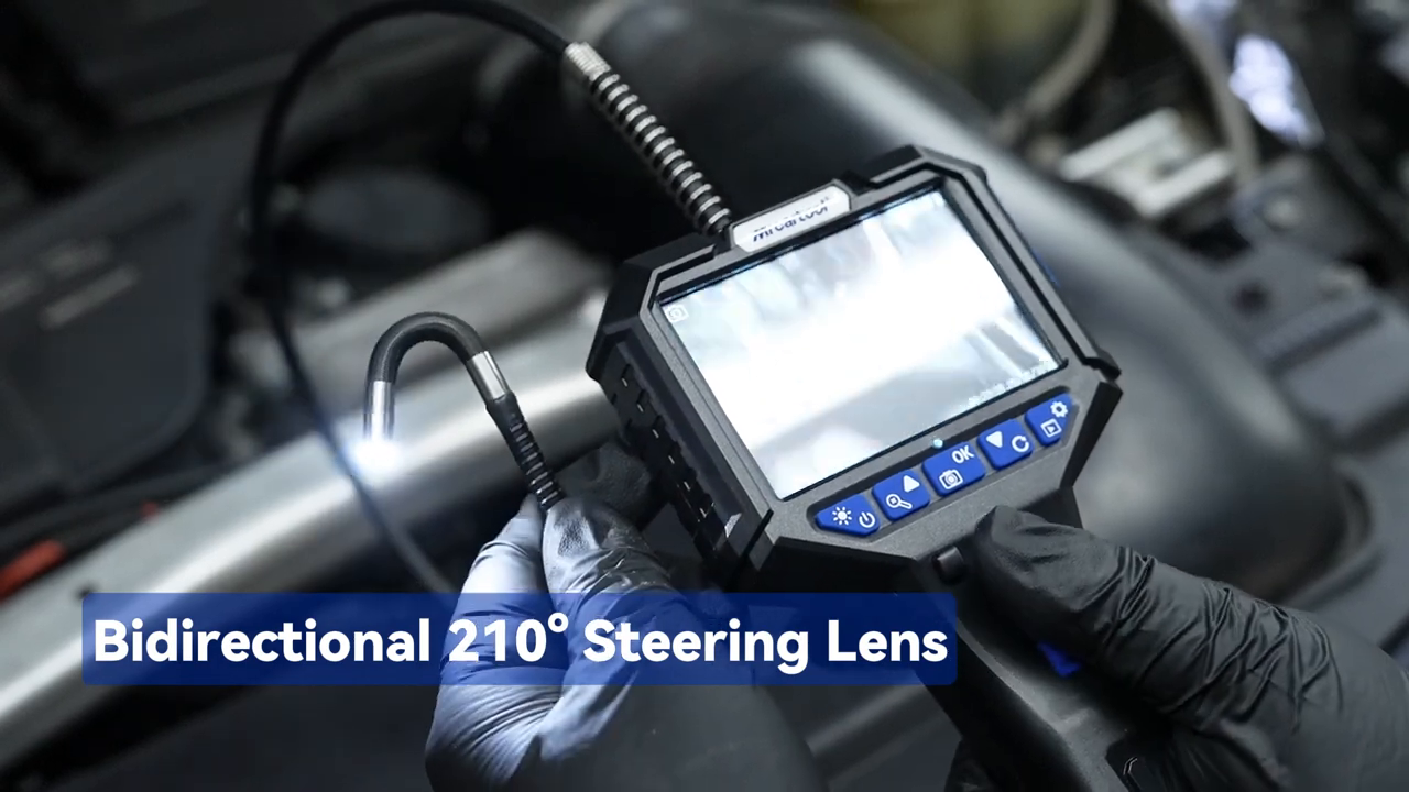
When a straight-ahead camera cannot show whether a pattern continues around the crown edge, cylinder wall, or valve face, use an articulating borescope that can reposition the view without forcing the probe. The MRCARTOOL N150 articulating borescope is one 6.2 mm steerable route for building matched views and saving them for comparison. More viewing access improves the evidence atlas, but it still cannot identify a liquid chemically, measure compression, prove sealing, or determine crack depth.
Disable the engine against starting, let it cool, and keep the probe away from moving parts. Never force it through an obstruction. This guide treats vision as one witness in a larger forensic file.
Quick answer: Describe the image before naming a cause. Capture matching crown, edge and wall views across adjacent cylinders, control light and probe angle, then pair repeatable differences with coolant, fuel, compression, leakage and misfire evidence before deciding on teardown.

In this guide
Describe the image before naming a cause
Write observable features: location, area, texture, reflectivity, color, wetness, deposit edge, machining marks, scoring direction, and foreign material. “Bright crescent on intake side, sharp boundary, wet droplets at edge” is more reusable than “coolant leak.” Include what is not seen: no pooled liquid, no wall scoring, no valve-edge anomaly. Avoid judging scale unless the probe has a known reference.
Camera behavior matters. Automatic exposure can make a clean surface look glowing and a carboned surface black. An LED reflected from liquid produces a bright point that resembles polished metal. Lens contamination adds haze. Record probe orientation, steering direction, light level, and piston position so another view can be reproduced.
| Visible feature | Possible explanations | Needed confirmation |
|---|---|---|
| Unusually clean crown area | Washing, recent repair, combustion variation, viewing angle | Fluid history, pressure/sealing, repeated view |
| Wet reflective film | Fuel, coolant, oil, cleaner, condensation | Odor/chemistry handled safely, fluid loss, injector/sealing evidence |
| Vertical wall lines | Normal honing, debris scoring, reflection | Matching-angle wall survey, compression/leakage evidence |
| Heavy local deposit | Oil/fuel pattern, temperature/flow difference | Plug, trims, oil use, injector and mechanical checks |
Make the cylinder views comparable
Begin with a cool engine and a documented disable procedure. Remove plugs according to service information, protect open wells, and label positions. Place each piston at a comparable height by the approved turning method; never rotate the engine with the probe inserted. Wipe the camera lens between cylinders and use the same light level, orientation, and capture distance.
Take a standard set: crown center, intake edge, exhaust edge, representative wall quadrants, and accessible valve faces if the probe can steer without contact. Save files with vehicle, cylinder, view, and date rather than relying on the instrument’s sequence number. The adjacent cylinders become internal controls and often provide better context than a generic online photograph from a different engine.
Build an adjacent-cylinder atlas
Lay the matching views in a grid. Look first for repeatable differences, not isolated dramatic frames. Is the clean patch present in every exposure? Does it remain when the probe rotates? Are wet areas still present after a controlled wait? Do wall marks run through several crank positions, viewed only after the probe is removed and the engine is safely repositioned?
Add plug appearance, misfire counter, compression screen, and fluid history beside each column. This atlas lets the image support or challenge other evidence. A cylinder with cold-start misfire, unexplained coolant loss, a persistently steam-cleaned region, and pressure-test evidence deserves a coolant-path investigation. The picture alone does not deserve that conclusion.
Interpret clean or wet surfaces cautiously
Coolant intrusion can remove or alter deposits, but quantity, engine temperature, dye, combustion, and time change the appearance. Fuel can wash oil and carbon, especially with an injector fault or repeated unsuccessful starts. Oil may appear amber, dark, or reflective depending on contamination and lighting. Water condensation after storage is another context. Never taste, touch, or ignite an unknown liquid.
Check reservoir level and pressure history, cooling-system pressure behavior under the correct procedure, exhaust evidence, plug deposits, fuel pressure decay, injector control, oil condition, and misfire timing. Chemical block tests, gas analysis, injector balance/flow, and leak-down answer different questions. Choose the least invasive next test that can distinguish the leading hypotheses.
Read edges, walls, and valve faces
An articulating probe is most valuable beyond the crown center. Sweep the squish area, head surface, valve margins, and reachable wall. Look for impact marks, foreign material, deposit-free trails, melted edges, cracks, or localized damage—but describe before diagnosing. A line can be a casting boundary, reflection, carbon crack, or real fracture. Surface vision cannot reveal subsurface damage.
Wall scoring should be compared in direction, length, depth appearance, and cylinder location. Normal crosshatch can remain visible; polished thrust areas vary with engine life. Valve faces may show uneven deposits without proving leakage. If a concerning feature persists through angle and light changes, confirm with compression, leak-down, oil consumption, or disassembly as appropriate.
Pair the image with fluid and misfire evidence
Create an evidence matrix rather than a caption contest. A coolant hypothesis gains weight from repeatable coolant loss, cooling-system pressure behavior, cold-start misfire, plug/crown comparison, exhaust gas evidence, or leakage observed under a controlled test. A fuel hypothesis gains weight from injector leakage, fuel pressure decay, rich trims, fuel dilution, and a wet plug. Mechanical damage gains weight from compression/leakage, crankcase pressure, noise, and oil use.
| Hypothesis | Borescope contribution | Stronger companion evidence |
|---|---|---|
| Coolant wash | Repeatable clean/wet pattern | Pressure test, fluid loss, gas/chemical evidence |
| Fuel wash | Wet/clean area after injector event | Injector leakage/flow, trims, fuel dilution |
| Oil entry | Deposits or wet film distribution | Oil consumption, plug, leak-down, PCV/guide evidence |
| Normal variation | Stable difference without symptoms | Good sealing, stable fluids, comparable operation |
Choose the next confirmation test
Choose a test that changes the decision. If the question is sealing, perform relative compression then the specified absolute or leak-down test. If it is coolant entry, use the manufacturer’s cooling-system pressure and combustion-gas procedures. If it is an injector, isolate command and leakage without hydrolocking a cylinder. If the image suggests foreign-object damage, stop running and plan safe access.
Do not perform every test because the borescope is inconclusive. Rank hypotheses by symptom timing and risk, then select the least invasive discriminator. Reinspect after a controlled test only when no liquid or pressure can eject the probe and the engine is disabled. A before/after image can be strong evidence if the view is truly matched.
Compare borescope routes
Public model-level sales share is not available as defensible evidence. Depstech and Teslong offer accessible camera/probe routes; Vividia and Snap-on provide workshop-oriented options; Olympus/Evident industrial scopes emphasize optics, measurement, and service at a specialist band. Fixed-head phone scopes are inexpensive but may struggle to see valve faces or crown edges. Articulation improves access, not diagnostic certainty.
| Route | Best fit | Tradeoff |
|---|---|---|
| Fixed forward/side camera | Basic crown and wall survey | Limited steering and repeatability |
| Articulating handheld scope | Matching edge, valve, and wall views | More moving parts and technique |
| Industrial videoscope | Optics, documentation, measurement options | Specialist cost and support band |
| Disassembly | Direct access and physical inspection | Most invasive, time and sealing work |
| Outsource/no-buy | Rare engine inspection | Less immediate ownership value |
If the missing evidence lies beyond the straight-ahead view, choose an articulating borescope that can reach the required surface with safe clearance and repeatable lighting. The N150’s steerable 6.2 mm probe and self-contained capture can help build matched crown-edge, wall, and valve-face views instead of relying on one bright center image. Record the orientation and compare adjacent cylinders; do not let a closer picture become a stronger causal claim than the pixels support.
A lower-cost fixed scope is enough when central crown and wall checks answer the recurring question. Industrial equipment is the better route when optics, measurement traceability, interchangeable probes, or local service are required. When the combined image and mechanical evidence already justify direct access, disassembly may be more useful than another camera. Articulation solves a viewing problem, not the cause of the deposit or liquid.
Make lighting part of the evidence
For each cylinder, capture one frame at the lowest usable light and one at a higher matching setting. A feature that vanishes when glare moves may be reflection; a deposit boundary that stays fixed as the probe rotates is more likely physical. Keep the lens away from wet surfaces—touching liquid can smear the lens and make all later cylinders look alike.
Do not use digital zoom as proof of detail. It enlarges pixels and compression artifacts. Move or articulate only within safe clearance and preserve a wider orientation frame before a close view. If a suspected crack cannot be reproduced from two angles, label it “unresolved line” and choose another test rather than promoting it to a fracture.
Turn the atlas into a decision threshold
Before inspection, define what would change the job: evidence sufficient to run another controlled test, evidence that stops engine operation, or evidence that justifies disassembly. Foreign material, impact damage, pooled liquid after a verified dry state, or severe repeatable scoring can be stop findings. Minor deposit variation with normal compression and stable fluids may justify monitoring instead.
This threshold protects against the “interesting picture” problem. Articulating cameras reveal more surfaces, so they also reveal more harmless irregularities. The decision should come from the picture plus symptom, trend, and independent confirmation—not from the novelty of seeing inside.
Care for the probe as a measurement chain
Inspect articulation, sheath, lens, and tip before and after use. Count any detachable mirror or tip accessory in and out. Never leave a component in the cylinder. Clean with compatible materials and do not kink the shaft during storage. If steering becomes rough or the sheath is cut, remove the tool from engine work before a fragment becomes the new diagnosis.
Archive before-and-after views
After repair or a controlled cleaning/operating interval, repeat the same atlas: engine condition, piston position, probe orientation, light, and named views. Confirm the actual complaint with fluid levels, misfire data, compression/sealing, or oil use as relevant. A visually changed crown without symptom verification is not proof of a durable repair.
Archive original files rather than screenshots compressed by messaging. Note which images are descriptive, which hypothesis they supported, what independent test confirmed it, and what remained uncertain. A good borescope record may conclude “normal variation; no action” just as legitimately as it identifies an area for teardown. The instrument’s best contribution is often preventing an expensive diagnosis from being built on one shiny frame.
Atlas cautions before a teardown decision
Can bubbles or droplets identify coolant? No. Appearance cannot identify chemistry. Pair the observation with cooling-system loss/pressure, fuel leakage, oil evidence, safe sampling, and the appropriate confirmatory method.
Why compare neighboring cylinders if engines do not burn evenly? They provide vehicle-specific context under the same camera and recent operation. Natural differences remain, so adjacency is not a pass/fail standard; it identifies which features deserve correlation with cylinder-specific symptoms.
Can a borescope rule out a head-gasket leak? No. The leak may be intermittent, small, outside the field of view, or leave no unique visual mark. A normal-looking chamber reduces only the weight of visible-damage hypotheses; pressure, gas, fluid, and operating evidence still control.
The minimum comparable photo set
For each cylinder capture: a wide crown orientation frame, crown center, intake-side edge, exhaust-side edge, two wall quadrants, and any reachable valve face. Keep piston height, LED setting, lens cleanliness, and probe direction consistent. Add a second angle only for features that persist. Name files immediately; “IMG 0047” loses its evidentiary value after the plugs are reinstalled.
Then score the set against three questions: Is the feature unique to one cylinder? Does it survive angle/light changes? Does it align with a cylinder-specific symptom or independent test? One “no” does not erase the observation, but three “yes” answers justify a targeted confirmation test. If no safe confirmation exists without disassembly, record uncertainty and consult a specialist.
Avoid starting or rotating the engine with the probe present. Count tips/accessories before and after. If liquid is pooled, remove the probe and address hydrolock/fire/environmental risk by the approved method before any cranking. The camera is there to reduce unnecessary intrusion, not to become an obstruction inside the engine.
Decision rule: Escalate an image only when it is repeatable, materially different from comparable cylinders, and aligned with an independent symptom or test. Otherwise archive and monitor. The better the camera, the more incidental detail it reveals; disciplined description and a prewritten decision threshold keep that extra detail from turning into unnecessary teardown.
When sharing images with an engine specialist, send the complete matched set and operating context rather than the most alarming crop. A dramatic close-up without adjacent cylinders, piston position, fluid trend, and compression evidence invites the same overinterpretation the atlas was designed to prevent.









Comments 0
Questions, fixes, and real-world diagnostic notes from readers.
Be the first to share a diagnostic result or ask a follow-up question.