
A/C Pressures Look Normal but the Vents Stay Warm? Add Temperature and Airflow

Pressure Needs Context
Pressure is one coordinate, not an address. Without ambient temperature, humidity, operating state, pipe temperature, vent temperature, airflow, fan operation, and the vehicle’s specified refrigerant/charge, “normal pressure” can describe very different A/C systems—including one that is not cooling.
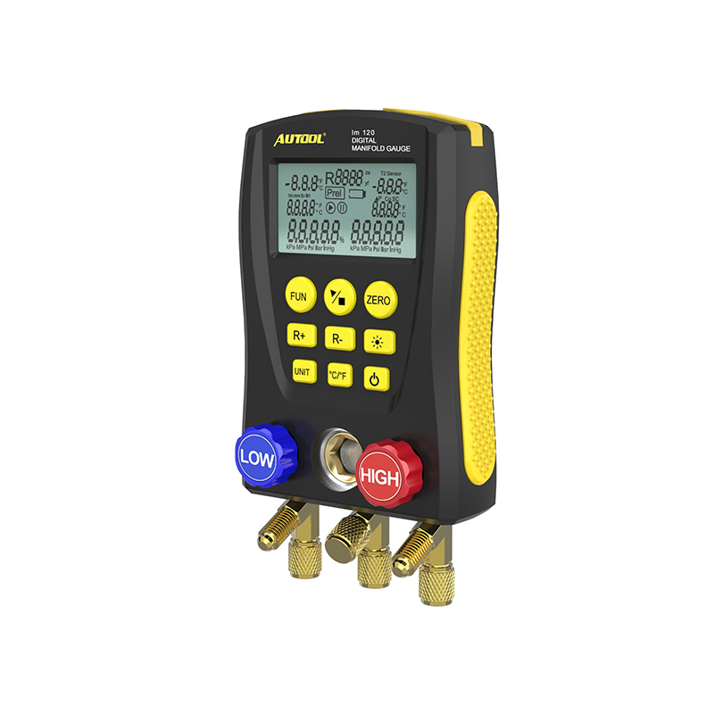
When pressure looks plausible but cooling does not, the useful next instrument is a digital manifold that can pair high- and low-side pressure with pipe temperature under the same stabilized condition. For a trained technician who already has the required refrigerant identification, recovery, vacuum, charge-by-mass, and leak-testing workflow, the AUTOOL LM120 refrigerant gauge set is one compact way to collect those pressure and external-temperature coordinates. Selecting the correct refrigerant is still essential, and the manifold does not identify refrigerant or replace the equipment needed to open and service the circuit.
This guide builds a three-coordinate climate map: refrigerant-side pressure, heat movement/temperature, and air delivery. In the United States, refrigerant recovery and charging work requires trained personnel, approved equipment, and applicable Section 609 practices. Never vent or mix refrigerants; vehicle-specific charge mass and service data control.
Quick answer: Pressure is only one coordinate. Define the exact warm-air condition, stabilize ambient and operating inputs, pair both pressures with pipe and vent temperatures, prove condenser and cabin airflow, and use the vehicle-specific chart before opening or charging the system.
In this guide
Define the exact warm-air condition
Record vent temperature, ambient temperature/humidity, sun load, blower speed, recirculation setting, engine speed, vehicle speed, left/right/row differences, and how long the system has operated. “Warm” may mean never cools, cools at speed but not idle, starts cold then fades, one side warm, low airflow, or temperature that changes with engine load. Each points to a different part of the map.
Confirm customer controls and automatic-climate settings. A start/stop strategy, economy mode, engine overheat, wide-open throttle, low ambient lockout, battery-management event, or stored climate code can intentionally inhibit compressor output. Observe compressor command and actual behavior without assuming a clutch must visibly cycle; many modern variable-displacement or electric compressors behave differently.
| Pattern | Strong first direction | Common premature conclusion |
|---|---|---|
| Cool moving, warm at idle | Condenser airflow/heat rejection | Low refrigerant only |
| One side warm | Blend/air-distribution or zoned sensing | Compressor failure |
| Good airflow, poor temperature drop | Refrigerant/heat-transfer/control map | Blower fault |
| Cold evaporator, weak vent flow | Air filter, icing, door, blower path | More refrigerant |
Separate static from running pressure
Static pressure exists with the system equalized and does not reveal compressor pumping or charge mass by itself. It mainly reflects refrigerant temperature and composition. A contaminated or mixed refrigerant can produce misleading relationships. Running high- and low-side pressures describe the system only when ambient conditions, engine speed, airflow, compressor command, fan state, and stabilization are recorded.
Connect equipment by the approved procedure, identify refrigerant from the vehicle label and an identifier when required, purge/handle hoses without venting, and inspect couplers. Read both sides together. A single plausible low-side number can coexist with an excessive high side, weak compressor, restriction, or airflow problem. Never open manifold valves as an exploratory step.
Stabilize ambient and operating inputs
Follow the service information for doors/windows, blower, recirculation, engine speed, hood position, and test duration. Place ambient sensing away from condenser discharge or engine heat. Verify condenser/radiator fan speeds and that fins are not blocked or folded. Water sprayed on the condenser changes the test and should be used only as an intentional, documented diagnostic step where safe.
Keep battery support and engine cooling in mind. Low system voltage may alter fan, compressor, and control behavior. An overheating engine may switch off A/C. If high-side pressure, temperature, hose condition, or fan operation creates a danger, stop rather than waiting for a pattern to become more obvious.
Pair pressure with pipe temperature
Pressure-to-saturation conversion becomes meaningful only after selecting the correct refrigerant. Compare calculated saturation temperature with measured line temperatures at defined points to reason about superheat, subcooling, restriction, and heat exchange—but use the vehicle/OEM method, especially on systems with internal heat exchangers, accumulators, variable compressors, or unusual controls.
Attach temperature probes securely to clean pipe surfaces and insulate them from ambient air when the procedure calls for it. An infrared thermometer can misread shiny metal due to emissivity and background reflections. Measure inlet and outlet behavior across condenser, evaporator, receiver/drier, or restriction only where those points are physically and safely identified. Temperature change adds direction to two pressure numbers.
Check condenser heat rejection
The condenser must reject cabin and compressor heat to outside air. Confirm fan command and actual direction/speed, shrouds, debris, bent fins, radiator stack blockage, and hot-air recirculation. A fan can spin but underperform because of voltage drop, control, blade, or mechanical problems. Compare behavior at idle and with safe airflow; record the change rather than interpreting it as an automatic refrigerant diagnosis.
Excessive high-side pressure with poor heat rejection can coexist with a low side that looks familiar. Conversely, a variable compressor may reduce displacement when control inputs or protection logic demand it. Use scan data for pressure-sensor, compressor command, fan request, evaporator temperature, and fault context, then compare with independent measurement. The controller’s value and the manifold should tell compatible stories under the same state.
Check cabin airflow and blend control
Measure airflow and temperature at multiple vents. Inspect cabin filter, blower operation, evaporator icing, duct restrictions, recirculation door, and blend/mode doors. A hot heater core can overwhelm a cooled evaporator stream if a blend door or valve is wrong. Dual-zone systems can expose one actuator or temperature-sensor problem while refrigerant pressures remain entirely plausible.
Evaporator inlet/outlet or sensor data may reveal icing or an incorrect temperature report. Do not insert probes through moving doors or fan paths. Use actuator tests and calibration only when vehicle coverage and procedure are verified; a successful command does not prove door foam, linkage, or actual air path.
| Coordinate | Measure/observe | Decision it informs |
|---|---|---|
| Pressure | High/low sides under defined state | Refrigerant-side pattern and compressor response |
| Temperature | Ambient, lines, vents, sensor data | Heat pickup/rejection and air mixing |
| Airflow | Fans, filter, blower, doors, vehicle speed | Whether heat exchangers and cabin receive air |
Use patterns instead of universal numbers
Avoid charts that promise one pair of pressures for every vehicle. Refrigerant type, ambient conditions, charge, heat load, compressor strategy, fan control, and architecture alter the pattern. Use the exact service chart and record the test state. A “normal-looking” pair copied from a different system can normalize a fault.
Think conditionally: both sides high with poor condenser airflow suggests a heat-rejection investigation; both sides close together despite strong command can suggest weak pumping, but variable displacement and equalization state must be considered; low suction with temperature evidence across a restriction can support a restriction hypothesis. Every pattern requires confirmation and boundaries, not a parts list.
Compare manifold routes
No reliable public model-level share dataset supports a market ranking. Fieldpiece and Testo offer connected professional HVAC ecosystems; Robinair and Mastercool provide established automotive service routes; Yellow Jacket emphasizes manifold/recovery equipment; analog gauges remain an entry route. Refrigerant identifiers, recovery/recharge stations, leak detectors, scan tools, and airflow instruments answer separate questions and may be mandatory companions.
| Route | Best fit | Main tradeoff |
|---|---|---|
| Analog manifold | Basic trained pressure work | Manual conversion, no integrated temperature |
| Digital pressure/temperature manifold | Faster paired measurements and logging features | Correct refrigerant/setup still essential |
| Automotive RRR station | Controlled recovery, vacuum, charge by mass | Service, refrigerant, certification, higher band |
| Connected HVAC ecosystem | Multi-probe heat-transfer workflow | General HVAC may not cover vehicle procedures |
| Outsource/no-buy | Low-volume owners or unknown refrigerant | Less immediate control, often safest |
If the missing evidence is paired pressure and pipe temperature, use a digital manifold that supports the vehicle’s refrigerant and the technician’s hoses, couplers, and working range. The LM120 combines those coordinates in a compact display, which can reduce manual conversion during a stabilized test. If the missing capability is refrigerant identification, compliant recovery, vacuum, or charge accuracy, choose an automotive RRR route instead; a manifold alone cannot complete that work.
A connected Fieldpiece or Testo ecosystem makes more sense when multi-probe HVAC correlation is the recurring need, while Robinair or Mastercool equipment better fits a shop built around complete automotive refrigerant service. The choice should follow the unanswered diagnostic question, not the number of functions on one display.
Build one stabilized A/C data row
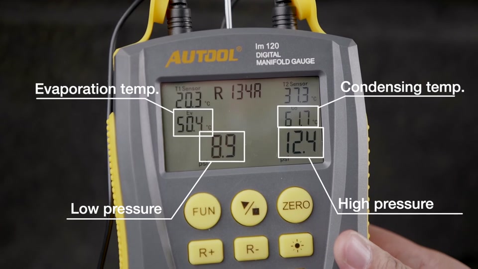
For every reading set, write ambient dry-bulb condition, humidity if available, engine speed, blower/recirculation, doors/windows, high/low pressure, selected refrigerant, relevant pipe temperatures, vent temperature, fan state, compressor command, and elapsed stabilization time. If any one condition changes, start a new row. This prevents a post-fan pressure from being paired with a pre-fan line temperature.
Calculate or interpret saturation-related values only after confirming the refrigerant. An LM120 display can automate conversions, but selecting the wrong refrigerant produces a precise-looking wrong result. Label every saved screen with the selected type. If contamination is possible, stop and identify/recover with appropriate equipment rather than tuning a diagnosis around uncertain chemistry.
Separate comfort from refrigerant work
Many warm-air complaints can be diagnosed without opening the circuit. Scan HVAC and powertrain modules, inspect fans and filters, compare vent zones, command doors where supported, and observe pipe temperatures. This “closed-system first” route preserves refrigerant, avoids introducing air/moisture, and may reveal that no pressure service was needed.
Only attach manifold equipment when pressure evidence can distinguish current hypotheses and the technician is authorized and equipped. Hose connection loses a small amount of refrigerant and adds contamination risk; repeated curiosity connections are not neutral. A low-volume owner may get better value from temperature/airflow checks and a certified A/C shop than from purchasing a manifold alone.
Look beyond the first cool minute
Run long enough to reproduce fade while monitoring safety. Icing, heat soak, fan cycling, blend-door drift, compressor protection, and evaporator-sensor errors can appear after initial cooldown. Graph vent and line temperatures against pressure if tools allow. A system that reaches a good vent temperature briefly but cannot maintain it tells a different story from one that never transfers heat.
Verify cooling under the original condition
After the proven airflow, control, electrical, leak, refrigerant, or mechanical repair, remove test aids and reassemble shrouds, filters, doors, connectors, and caps. If the refrigerant circuit was opened, follow the approved recovery, evacuation, leak-check, oil, and charge-by-mass procedure. Never judge charge solely by pressure.
Repeat the map under the original ambient, idle/road, blower, and zone condition as closely as practical. Record high/low pressure, key line temperatures, vent temperature, fan/compressor command, and airflow. Confirm no leaks or stored climate faults and that cooling remains stable after the duration that originally failed. The best closing sentence connects all three coordinates: pressure responded within service expectations, heat moved across the intended exchangers, and air delivered that cooling to the cabin.
Map-reading traps
Why can static pressure look normal with the wrong charge? Once temperatures equalize, static pressure largely reflects refrigerant saturation behavior, not total mass. A partly charged system can show plausible static pressure while lacking enough refrigerant flow during operation.
Can I add refrigerant until the low side looks right? No. Pressure is not a substitute for leak diagnosis, refrigerant identification, recovery, vacuum, and charge by specified mass. Adding by one gauge can overcharge the system, mix refrigerant, or hide airflow/control faults.
What if vents cool only while driving? Increased condenser airflow is a strong branch, but engine speed and compressor strategy also change. Confirm fan command/performance, heat-exchanger condition, pressure/temperature response, and vehicle-specific control rather than replacing a fan from the symptom alone.
A closed-system-first triage
- Reproduce the exact vent/zone/idle-or-road complaint and save climate/powertrain faults.
- Confirm blower volume, cabin filter, recirculation, blend/mode behavior, and vent temperatures.
- Inspect condenser stack and verify commanded versus actual fan operation.
- Confirm compressor command/behavior and vehicle voltage using scan/visual evidence appropriate to the design.
- Only then, when pressure will discriminate the remaining hypotheses and trained equipment is available, identify refrigerant and attach the service set.
- Pair both pressures with ambient, pipe temperatures, airflow state, and the exact chart.
This order often finds a blocked filter, failed fan, blend-door problem, or control inhibit without opening the refrigerant-side connection. It also reveals when a manifold alone is an incomplete purchase: safe refrigerant work may require an identifier, recovery/recycling/charging station, vacuum equipment, calibrated mass measurement, leak tools, training, and current service data. Compare the cost of the complete working method, not one attractive instrument.
Decision rule: Buy or use a digital manifold when the next unresolved question genuinely requires paired refrigerant-side pressure and temperature, and when the rest of the compliant service chain already exists. If the complaint is explained by cabin airflow, blend control, fan performance, tool coverage, or an unknown refrigerant, solve that branch first. The instrument should reduce uncertainty, not create a reason to open a sealed system.
One final ownership check is hose and probe serviceability. Replaceable, correctly rated hoses, seals, couplers, and temperature probes matter more over time than display novelty. Confirm parts availability and leak-check the service set by its instructions before trusting a beautifully stable reading.










Comments 0
Questions, fixes, and real-world diagnostic notes from readers.
Be the first to share a diagnostic result or ask a follow-up question.