
Toyota Auris P0A82 and a Battery Fan Stuck on High: A Camera Bolt Shorted the Command Wire

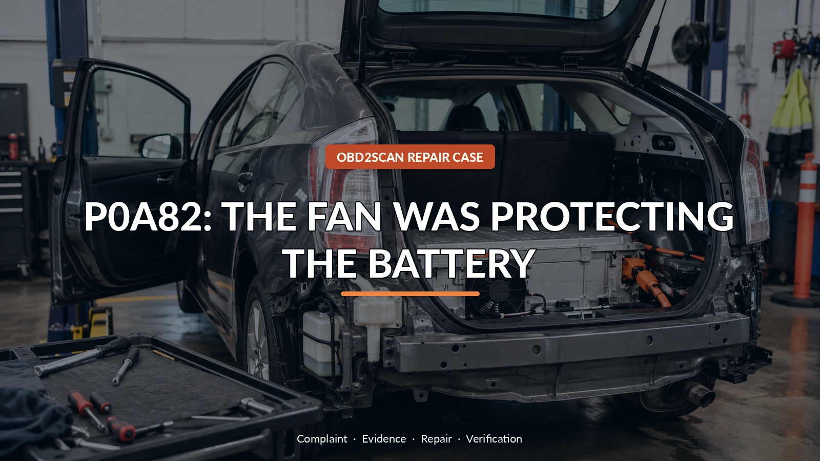
P0A82: The Fan Was Protecting The Battery
The Toyota Auris hybrid carried extra surveillance equipment throughout the cabin and displayed a hybrid warning. Code P0A82-123 pointed to battery-cooling fan performance. The fan was not dead; it ran continuously at high speed, largely masked by the sound of the added electronics. That was the first reversal. Maximum fan speed was a fail-safe response, and the fault sat in the small control wire—not in the high-voltage battery or the fan motor.
After the Toyota procedure identifies an accessible low-voltage command circuit, an automotive meter/scope can help answer whether PWM exists and whether the wire is shorted. The AUTOOL DM303 can support those bounded checks. DM303 can support accessible low-voltage PWM, continuity and K/CAN checks only after Toyota information identifies safe test points; it is not an HV-rated isolation procedure, cannot prove zero high voltage and must never be used inside the traction-battery enclosure by an untrained person.
This repair involved access near a hybrid battery and is not a DIY guide. Qualified hybrid personnel must follow the vehicle’s shutdown, wait-time, prove-dead and reactivation procedure. The transferable lesson is that an aftermarket installation earns inspection only after the failed circuit is mapped to its path.
Quick answer: The battery fan’s maximum speed was a failsafe. A surveillance-camera bolt grounded its PWM command wire; repairing the wire and mounting restored closed-loop control.
In this guide
- A fan stuck on high can be a protective response
- Read the information code before opening anything
- Map command, feedback and serial reporting
- Stop at the high-voltage training boundary
- A flat command line localizes the low-voltage branch
- Let continuity guide the trim removal
- Repair the wire and the mounting method
- Command every fan speed and clear the repair-created codes
A fan stuck on high can be a protective response
A high-speed cooling fan can sound like the failed component, but it may be doing exactly what the controller requests when feedback or command is implausible. The INF subcode established the battery fan fault as the event that initiated the warning rather than a secondary consequence. Before removing trim, the technician mapped the loop: hybrid control sends a speed command, the fan returns feedback, and the battery module reports that state back over serial communication.
Read the information code before opening anything
The vehicle’s unusual equipment mattered because screws, brackets and wiring had been added near factory harnesses. It did not justify ripping out the conversion or blaming the installer from the doorway. The inspection recorded equipment locations and compared them with the factory command-wire route. This kept the hypothesis testable: if added hardware caused the fault, a physical intersection with the affected circuit should be found.
Map command, feedback and serial reporting
Access to the battery-control area required the manufacturer shutdown sequence, including securing the key, disconnecting the 12 V source, removing and securing the service disconnect, waiting for capacitors and proving the specified points dead with suitable rated equipment. A general-purpose automotive tool does not prove an HV system safe. If training, PPE, service information or rated instruments are missing, stop and refer the vehicle.
Stop at the high-voltage training boundary
With the high-voltage system isolated as specified and the approved low-voltage test state established, the fan command sat fixed at 0 V instead of carrying the expected PWM. A grounded command could make the controller demand maximum fan speed as a protective default. Fan feedback and network activity still needed context, but the flat line localized the next check to the command conductor rather than the traction battery’s temperature or internal condition.
A flat command line localizes the low-voltage branch
Continuity testing showed the command wire shorted to chassis. The harness was not opened from end to end. Its route was compared with added fasteners until one surveillance-camera mounting bolt aligned with the circuit. Beneath the trim, that bolt had pierced or crushed the wire insulation and held the conductor to body ground. The electrical evidence and physical damage now told the same story.
| Finding | Interpretation |
|---|---|
| Fan runs continuously at high speed | Fail-safe operation is possible; motor is not open |
| P0A82-123 is first event | Cooling-fan loop deserves priority |
| Command fixed at 0 V | Investigate grounded low-voltage command branch |
| Camera bolt contacts routed wire | Aftermarket installation physically confirms cause |
| PWM and speed control return after repair | Closed-loop operation restored |
Let continuity guide the trim removal
The wire was repaired to automotive harness standards, protected from movement and rerouted away from the fastener. The camera mounting method was changed so another bolt could not repeat the damage. Nearby conductors were inspected because a fastener rarely understands which single wire the code mentioned. Repairing copper while leaving the installation geometry unchanged would have made the fix temporary.
Repair the wire and the mounting method
After reassembly and proper system reactivation, the scan tool commanded the fan through its speed range. PWM returned on the command line, feedback followed and the fan no longer remained at maximum speed. Codes generated intentionally while the service disconnect was removed were distinguished from the original P0A82 event and cleared only after all connectors and covers were restored.
Command every fan speed and clear the repair-created codes
Another Auris with P0A82 may have a blocked inlet, debris-filled fan, failed motor, supply issue, feedback fault or battery-temperature problem. Do not search blindly for a screw. Start with the subcode, verify actual fan behavior and compare command with response. Inspect aftermarket work when the circuit route earns it, and maintain the high-voltage boundary even when the failed wire itself carries ordinary low voltage.
The dramatic hybrid warning did not require a dramatic high-voltage part. It required the high-voltage system to be treated with full respect while a very ordinary wiring fault was proved. For owners, the useful detail is any recent accessory installation near the rear cabin. For technicians, the useful discipline is to map the loop first and open trim only where the signal and the route meet.







Comments 0
Questions, fixes, and real-world diagnostic notes from readers.
Be the first to share a diagnostic result or ask a follow-up question.