
2014 GMC Sierra Lost Power Steering and Three Modules: Corrosion at X185 Broke the Path

Good Data Here, Missing After X185?
Quick answer: The module list described a missing network region, not three failed controllers. Data existed at the BCM but did not reach the steering side; corrosion in connector X185 interrupted the path, and restoring its pins brought communication and steering assist back. This article follows one documented vehicle. It explains the evidence chain, not a universal failure rate or a direction to replace the same part on every similar car. Stop whenever the test would involve overheated brakes, high current, moving parts, refrigerant handling or an uncontrolled road condition.
When two sides of an inline connector must be compared without spreading terminals, correctly sized back-probe and breakout leads matter; the AUTOOL 92-Piece Circuit Test Lead Kit provides multiple adapter routes for use with a suitable meter or scope. The lead kit is not a scanner or meter, cannot identify X185, and does not make probing CAN, airbag or steering circuits safe without exact pinouts and terminal-fit discipline.
Three silent modules and lost steering suggested a large network failure, yet the fault changed location across the vehicle. Measuring at both ends of the path reduced the problem to corrosion in one intermediate connector.
Quick answer: The module list described a missing network region, not three failed controllers. Data existed at the BCM but did not reach the steering side; corrosion in connector X185 interrupted the path, and restoring its pins brought communication and steering assist back.

In this guide
Treat steering loss as a safety stop
Loss of electric steering assist is a safety stop. Keep the Sierra stationary until steering effort, charging voltage and basic mechanical freedom are known. A network scan showed the ABS, power-steering controller and steering-angle sensor missing, so the fault affected a region rather than just the steering motor. Preserve the original condition before changing it. The first observation is the control sample against which every later test must be compared.
List the silent modules by location
The DLC measured 120 ohms across pins 6 and 14 in the documented case. That value can suggest one terminating leg is absent, but resistance must be measured with the correct vehicle power-down procedure. It does not prove which terminator, connector or module is open. Use service information for the exact engine, build date and options. A correct method on the wrong terminal can create a precise but useless result.
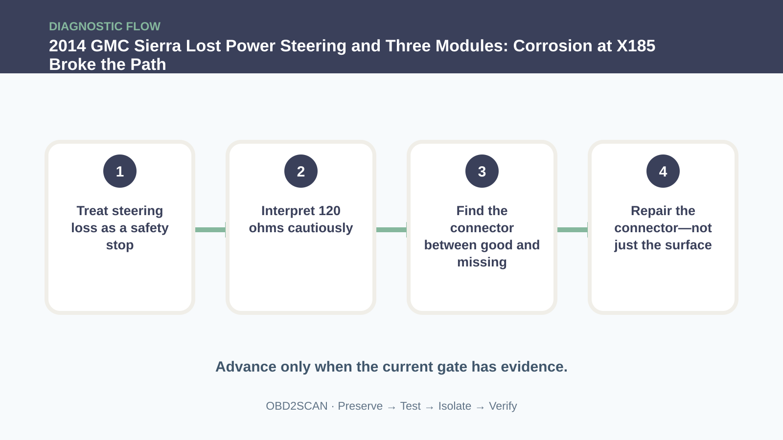
Interpret 120 ohms cautiously
Use the topology to decide where the good data ends. Communication signals were present at BCM connector X6 pins 24 and 25 but did not reach the power-steering side. Two measurement locations create a boundary; replacing a silent module before finding that boundary would skip the most useful evidence. Treat prior work as evidence, not blame. A repair that made no change can narrow the case when its installation and test conditions are verified.
Prove data at the BCM side
The diagram showed connector X185 between the chassis and body harness near the underhood fuse block, and it also carried the steering-angle sensor supply. Inspect its seals, backshell, routing and pin faces. Moisture can create resistance or bridge adjacent terminals without an obvious broken wire. At this stage, separate what was observed from what is inferred. The observation should remain true even if the current theory is later rejected.
| Observation | What it supports | What it does not prove |
|---|---|---|
| ABS, steering and angle modules silent | A network region is missing | Three modules are failed |
| DLC reads 120 ohms | One terminating path may be absent | X185 is proved |
| Data is good before X185 | The fault lies farther downstream | Every pin after it is bad |
| Pin repair restores modules | Connector corrosion was causal here | No water path remains |
Find the connector between good and missing
Green or dull pins were visible in X185. Disconnect the battery and wait as required before terminal work, especially around steering and brake networks. Use only correctly sized probes; forcing a pin can turn a cleanable terminal into a permanent intermittent connection. This is the decision point in the documented case. Its value comes from changing one bounded condition while leaving the rest of the system intact.
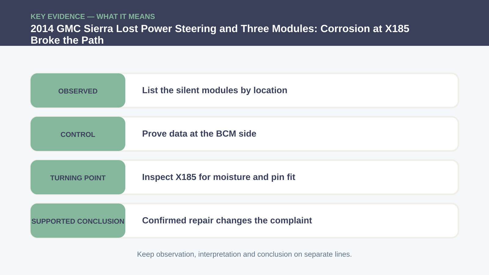
Inspect X185 for moisture and pin fit
Clean or replace terminals according to GM procedure and verify retention with the approved gauge. Address the water path and seal, not just the visible oxide. A connector that tests well while open can fail again when latched, hot or vibrating if pin tension remains weak. A confirmed component still needs a repair that restores sealing, support, torque, routing or terminal fit—the physical conditions that keep the fault from returning.
Repair the connector—not just the surface
After repair, restore power and scan every previously missing module. Verify normal steering assist, steering-angle plausibility, ABS communication and network resistance in the appropriate power-down state. Clear codes, cycle the ignition and repeat with the harness positioned as installed. Reassemble protective covers and retainers before declaring success. A diagnostic shortcut must not become the next failure mechanism.

Verify steering and every module together
The case’s broader lesson is geographic: three silent modules can describe the far side of one connector. Combining a topology map with a before-and-after signal comparison makes the connector inspection earned rather than another visual guess. Use the customer’s original complaint as the final specification. A cleared code, quiet bay or one good key cycle is not equivalent to reproducing and passing that condition.
If you are bringing a similar symptom to a shop, arrive with the useful conditions rather than a requested part: whether the vehicle was cold or hot, the exact speed or switch position, which warning lamps appeared, what changed after a restart, and a chronological list of earlier repairs. A short video can preserve an intermittent sound or lamp pattern, but record it only while parked or with a passenger handling the camera. Ask the technician to retain the pre-repair scan and measurements, explain the test that separated the failed path from the alternatives, and show how the original complaint was repeated afterward.
For the owner or service adviser, a useful repair explanation has three parts: what was observed, why the decisive test narrowed the fault, and which original condition passed after the repair. It should also say what the test did not prove. That boundary prevents a memorable case from becoming an automatic parts recommendation.
The module list described a missing network region, not three failed controllers. Data existed at the BCM but did not reach the steering side; corrosion in connector X185 interrupted the path, and restoring its pins brought communication and steering assist back. The reusable lesson is narrower and more valuable: Let physical network geography drive the prose: measure before the connector, after it, then inspect the bridge only when the boundary is proven.










Comments 0
Questions, fixes, and real-world diagnostic notes from readers.
Be the first to share a diagnostic result or ask a follow-up question.