
Manitou Telehandler Winch Stayed Slow With Good Pump Flow: The Valve Block Was Leaking Internally

Good Flow, Low Pressure? Follow The Return Path
A Manitou telehandler’s winch remained slow even though the pump delivered about 70 liters per minute. The familiar phrase “weak hydraulics” had hidden two different quantities: oil was moving, but the circuit could not turn that flow into usable pressure at the load. Almost all of it was finding a lower-resistance way back to tank.
After a qualified technician has fully depressurized and opened an accessible area, an articulating inspection camera can document contamination, port condition or visible damage. The AUTOOL SVB308 is one example for that limited visual role. SVB308 can document accessible valve-block ports, contamination or surface damage only after the system is safely depressurized and opened by a trained technician. It cannot see a sealed internal crack, measure 70 lpm or certify high-pressure hydraulic integrity.
The system stayed near a 200-bar ceiling while roughly 74 liters per minute returned to tank. Replacing the outlet slice and capping external routes changed nothing. Splitting the valve bank raised pressure to 231.7 bar, supporting an internal leak in the main control block. Another company replaced the complete block and the operator reported normal operation. A rumored internal crack was never independently confirmed and should remain a rumor.
Quick answer: The pump delivered about 70 lpm, but nearly all flow returned to tank near a 200-bar ceiling. Isolation evidence supported an internal main valve-block leak.
In this guide
- Slow hydraulics require training before testing
- Separate pump flow from usable pressure
- Measure what returns to tank
- Do not let an adjusted relief become the story
- Block external escape paths one at a time
- Split the valve bank to localize the loss
- Know when more testing costs more than certainty
- Replace the block and verify the original winch load
Slow hydraulics require training before testing
High-pressure hydraulic diagnosis can inject oil through skin, drop loads and move machinery without warning. Lower and support attachments, release stored pressure, verify zero energy and use rated hoses, guards and remote test points. Only trained personnel should reproduce the slow function under load. Record oil temperature, engine speed, load, direction and cycle time because viscosity can transform leakage. Stop for hose movement, visible damage, aeration, overheating or any person entering a crush zone.
Separate pump flow from usable pressure
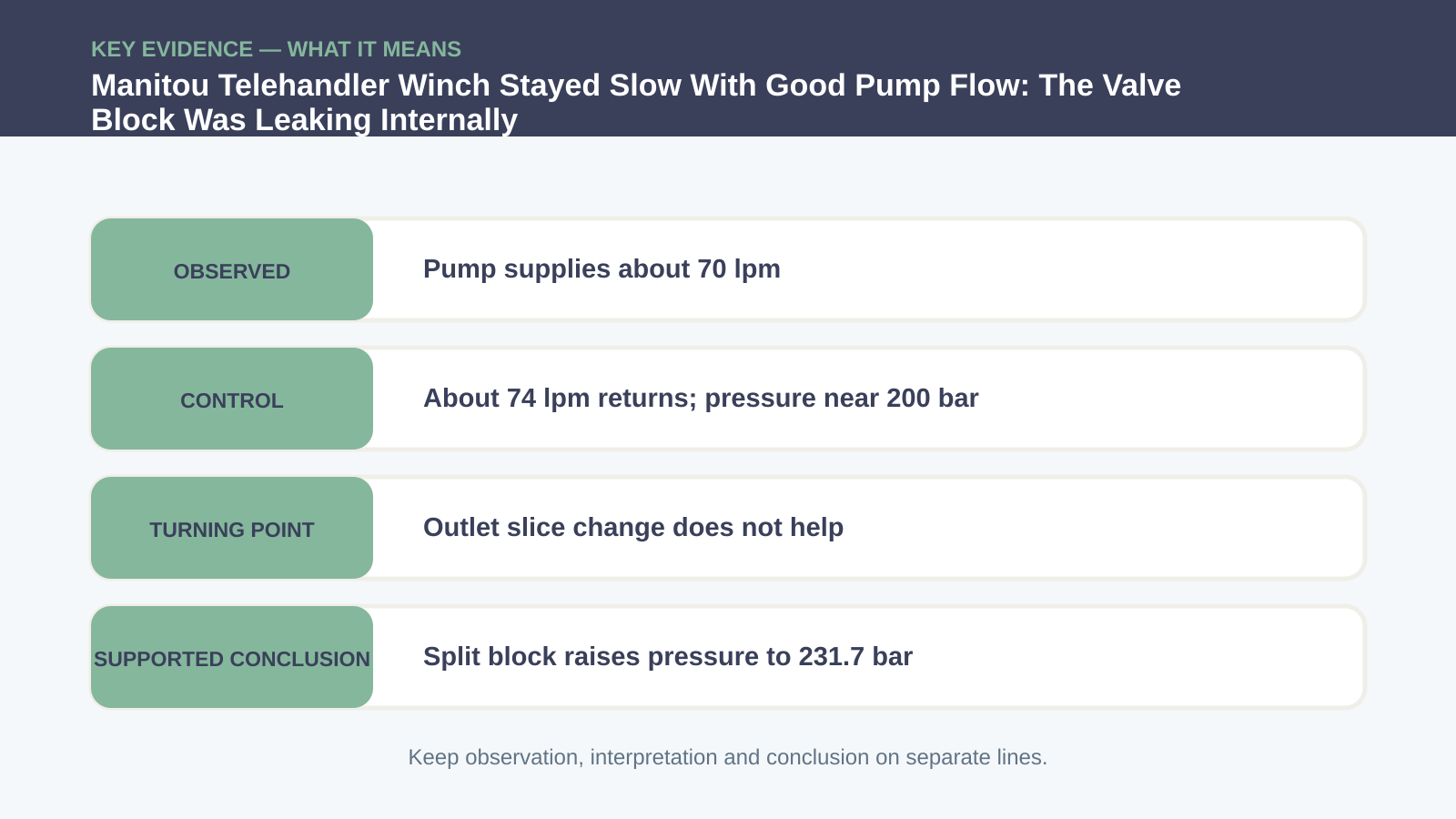
Flow and pressure answer different questions. A pump can deliver volume at low resistance and still fail to build pressure, while a healthy pump may show low flow when a compensator correctly destrokes. The documented pump produced about 70 lpm, close to the expected source flow for the test. Yet the function remained slow. Keep engine rpm and oil temperature consistent, place transducers on the specified points and compare commanded flow with usable pressure rather than calling the pump good from one unloaded measurement.
Measure what returns to tank
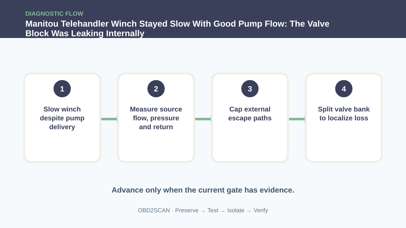
Return flow exposed where useful energy was going. Roughly 74 lpm came back toward tank while pressure struggled around 200 bar. Map every intended and unintended return route through the valve bank, relief path and auxiliary circuits. Do not assume all return flow means a relief valve is open; spool leakage, load checks, compensator passages and internal galleries can pass oil. A simultaneous pressure/flow view is more informative than adjusting a valve and waiting to see whether the winch feels faster.
Do not let an adjusted relief become the story
Relief adjustment was explored, and an outlet slice was replaced, without changing the ceiling. Those are not embarrassing detours; they are negative evidence. Record the original setting before any trained adjustment and never exceed component limits. A new slice that produces no improvement moves the problem beyond that local assembly. Repeatedly turning an unknown relief can create a dangerous overpressure while masking the real escape path.
Block external escape paths one at a time
External consumers and return paths were capped or isolated one at a time using rated equipment, yet the loss remained. Each cap test must follow a drawing and include pressure protection; blindly blocking a line can trap energy or remove a relief route. Compare the result after every isolation. When closing external paths does not change return flow or pressure, the evidence increasingly points inside the valve bank rather than toward cylinders, motors or remote hoses.
| Test state | Flow/pressure response | What it narrowed |
|---|---|---|
| Pump delivery checked | About 70 lpm available | Gross source-flow loss less likely |
| Return measured | About 74 lpm returning | Large internal escape path exists |
| Outlet slice replaced | ~200-bar ceiling remains | Outlet slice not the primary cause |
| Valve bank split | Pressure rises to 231.7 bar | Leak lies within isolated main block area |
Split the valve bank to localize the loss
Splitting the valve block changed the system response and pressure rose to 231.7 bar. That was enough localization to support internal leakage within the main control block. It did not reveal a specific crack. Further disassembly, specialized bench flow testing or destructive inspection might have named the internal gallery, but the added labor and contamination risk had to be weighed against replacing the assembly. Diagnostic certainty has an economic stopping point as long as the remaining claim stays no more specific than the evidence.
Know when more testing costs more than certainty
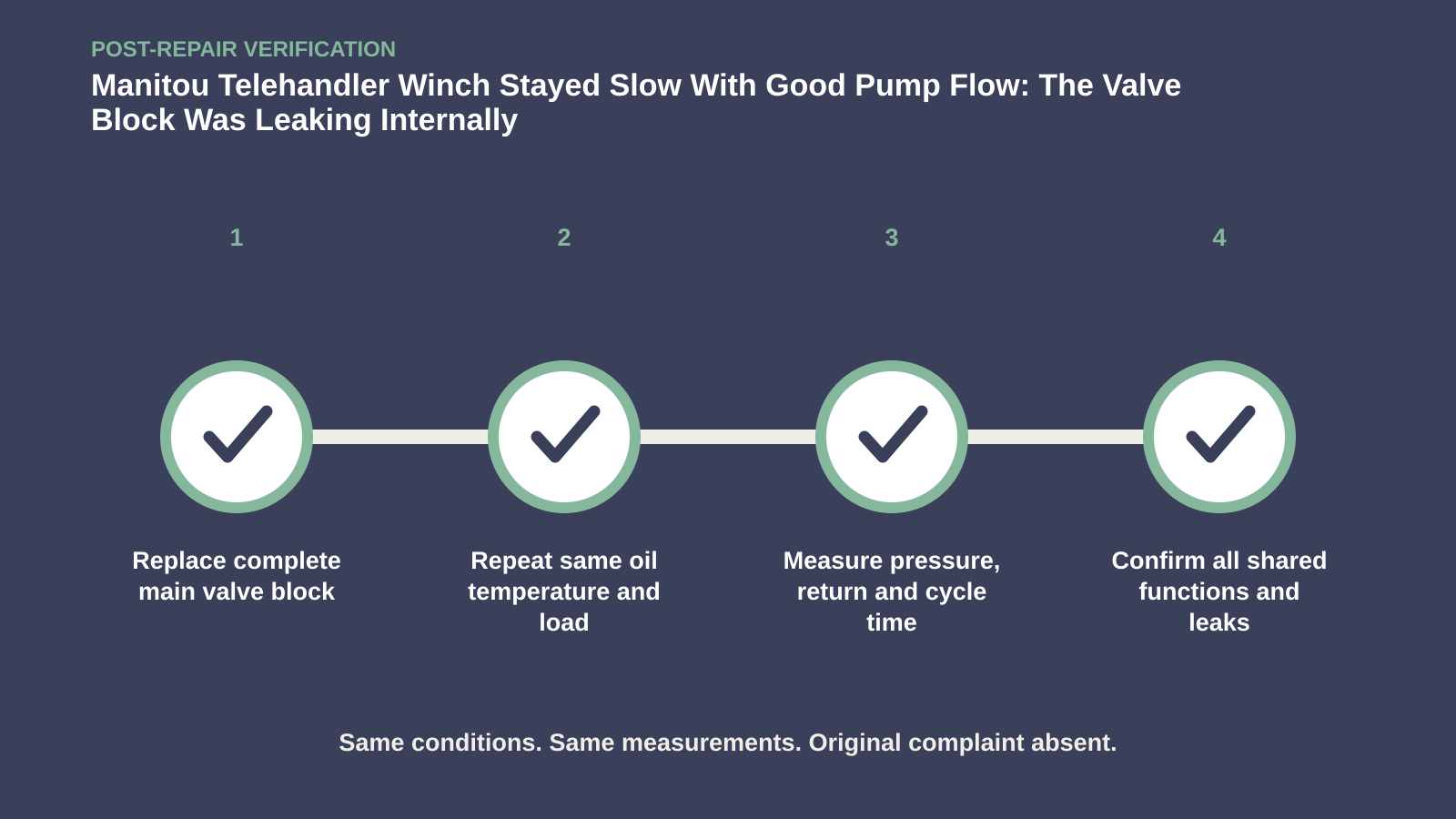
The complete block was replaced by another company, after which the operator reported that the winch worked as expected. Verify the original function with the same oil temperature, engine speed and representative load; record line pressure, return flow and cycle time. Inspect for leaks and confirm every function sharing the bank still behaves normally. If possible, obtain the replacement company’s measurements. The reported recovery supports the block-level conclusion, but it does not retroactively prove the unverified story of an internal crack.
Replace the block and verify the original winch load
Keep the failed-tests ledger with the machine: pump flow, return flow, slice change, external isolation and split-bank response. It prevents future technicians from repeating high-risk steps without new evidence. Cut open filters and inspect oil only under the contamination-control plan, and schedule a follow-up for temperature and leakage. This case teaches that good flow can coexist with poor work when the valve bank cannot hold pressure—and that the most honest repair story sometimes stops at the assembly boundary.
The pump moved plenty of oil; the circuit simply gave that oil an easier trip home. Following the return path justified a valve-block decision while leaving the unproven internal-crack detail exactly where it belonged: unclaimed.








Comments 0
Questions, fixes, and real-world diagnostic notes from readers.
Be the first to share a diagnostic result or ask a follow-up question.