
How to Use the MRCARTOOL 24V-to-12V OBD Power Adapter

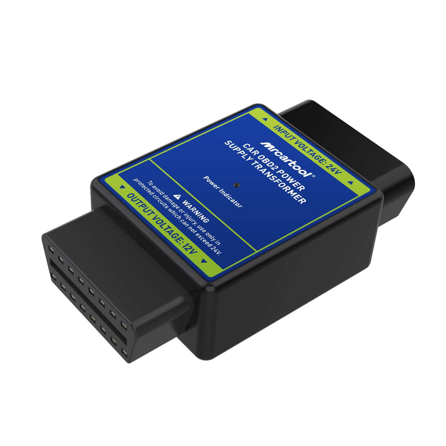
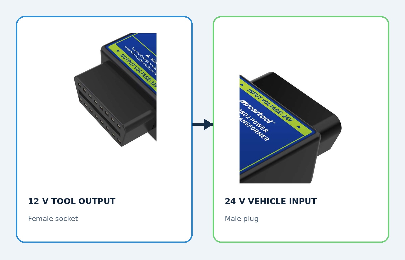
The MRCARTOOL 24V-to-12V OBD power adapter is an inline voltage converter for powering a compatible 12 V diagnostic device from a verified 24 V vehicle diagnostic connector. Its case is marked “Input Voltage: 24V” at the male plug and “Output Voltage: 12V” at the female socket. It changes supply voltage only; it does not translate diagnostic protocols, change connector pin assignments or make a passenger-car scan tool compatible with every truck.
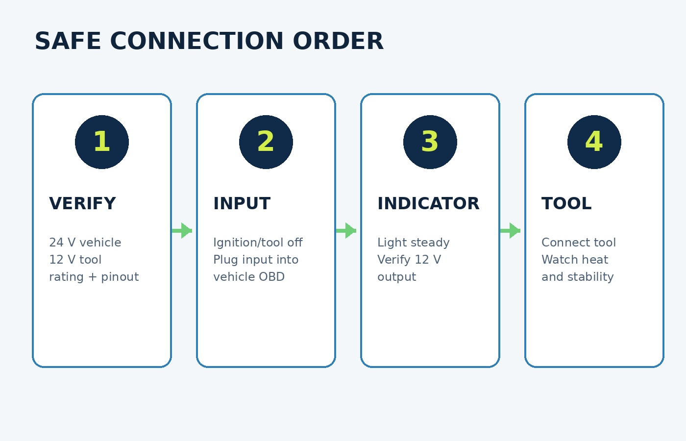
Quick answer: Identify the vehicle as a 24 V system and verify its diagnostic-connector power and ground pins from service information. Confirm the device requires 12 V, uses the same pinout and protocol, and draws less than the adapter’s current or power rating shown on the current label, package or manufacturer specification. With ignition and the diagnostic tool off, inspect both connectors, plug the adapter’s 24 V input into the vehicle and confirm the power indicator is steady. Verify 12 V output with an authorized test method, then connect the 12 V tool to the female output. Stop immediately for heat, odor, flicker, resets or unstable output. Disconnect the tool first and the adapter from the vehicle second.
In this guide
Understand what the adapter converts
The exact product page describes a stable 12 V output for OBD-II diagnostic tools and other compatible 12 V equipment on 24 V vehicles. The product image provides the decisive direction labels: 24 V input on the male vehicle side and 12 V output on the female tool side. An internal power indicator shows that input power is present. The page also claims overload, overvoltage and overheat protection, but protection is a final safeguard rather than a sizing method.
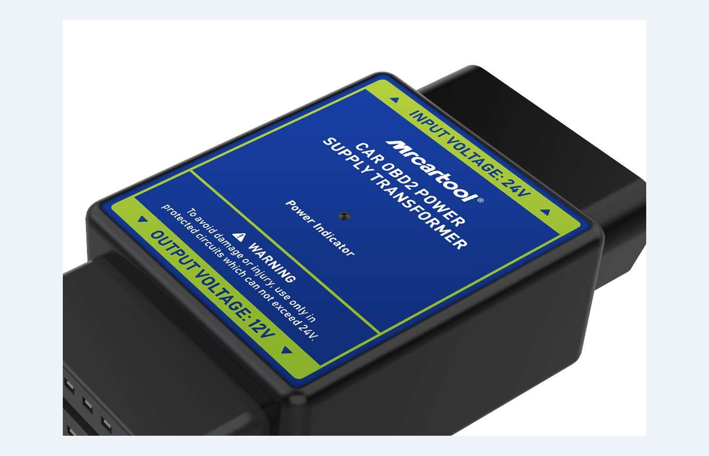
No output-current or wattage rating appears in the retained product copy or visible label. The page warns not to exceed the rated power range without stating that range. Therefore, obtain the current rating from the current package, device label or MRCARTOOL before use. Do not guess from connector size and do not connect a high-draw appliance. If a rating cannot be verified, limit the decision to no connection rather than assuming a small scan tool is safe.
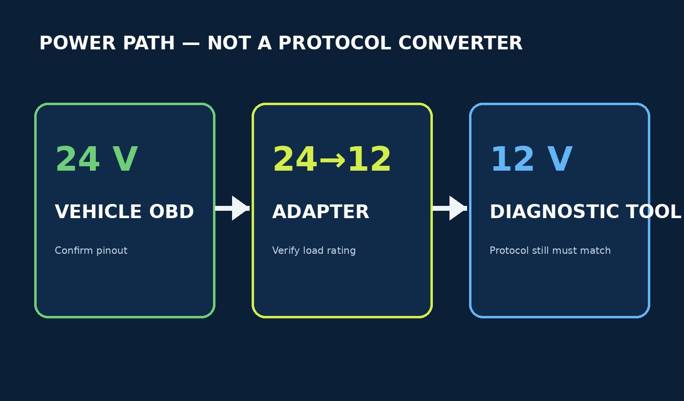
This is not a diagnostic-protocol converter. A physical 16-pin connector and correct 12 V supply do not prove that CAN voltage, pinout, J1939/J1708/OBD-II protocol or the scan tool’s vehicle coverage are compatible. Confirm electrical and communication compatibility separately.
Qualify the vehicle, connector and tool
1. Confirm the vehicle supply
Use the vehicle wiring diagram and a suitable meter to confirm the diagnostic connector’s power pin, ground pin, nominal 24 V system and key-state behavior. Heavy vehicles can use 24 V batteries while a specific diagnostic port already supplies a different voltage, or they can use a connector with non-passenger-car assignments. Never infer voltage or pinout from the vehicle class. If service information identifies a dedicated OEM diagnostic adapter, use it.
2. Confirm the 12 V device
Read the diagnostic tool’s input label and manual. It must accept a 12 V supply at the same connector pins and be designed for the vehicle’s communication protocol. Record normal and peak current demand, including startup and wireless accessory loads. Compare that demand with the adapter’s verified continuous and peak rating. Leave margin rather than operating at the limit; a converter can reset during a current surge even when average current appears acceptable.
3. Exclude unsuitable uses
Do not use the adapter for module programming, ECU flashing, battery support, vehicle starting, memory saving, powering motors/heaters or any job that requires a regulated service supply unless the vehicle, tool and adapter specifications explicitly approve it. Programming requires voltage stability and capacity that this page does not document. Do not wire either end directly to a battery; the exact unit is an OBD inline plug-and-play converter.
Inspect before connection
4. Turn everything off
Park securely, apply the parking brake and follow the vehicle diagnostic procedure. Switch ignition off and shut down the scan tool. Unplug other devices from the diagnostic connector. Keep the adapter away from pedals, steering, seat tracks, water, direct sun, heaters and engine heat. The product page specifically warns that high temperature can activate protection or impair operation.
5. Inspect the housing and connectors
Check the case seam, male pins, female terminals and power-indicator window. Reject bent, pushed-back, corroded, loose, contaminated, cracked or heat-discolored parts. Confirm the label remains readable and the input/output ends have not been modified. Inspect the vehicle port and tool plug in the same way. A forced connector can spread a terminal and create future intermittent faults.
Connect in the correct order
6. Insert the 24 V input into the vehicle
Keep the 12 V tool disconnected. Align the adapter’s male end marked Input Voltage: 24V with the verified vehicle diagnostic connector and insert it straight without rocking or forcing. Support the adapter so its weight does not lever the vehicle port. If it does not seat with normal pressure, stop and recheck keying, connector type and pin condition.
7. Check the power indicator and output
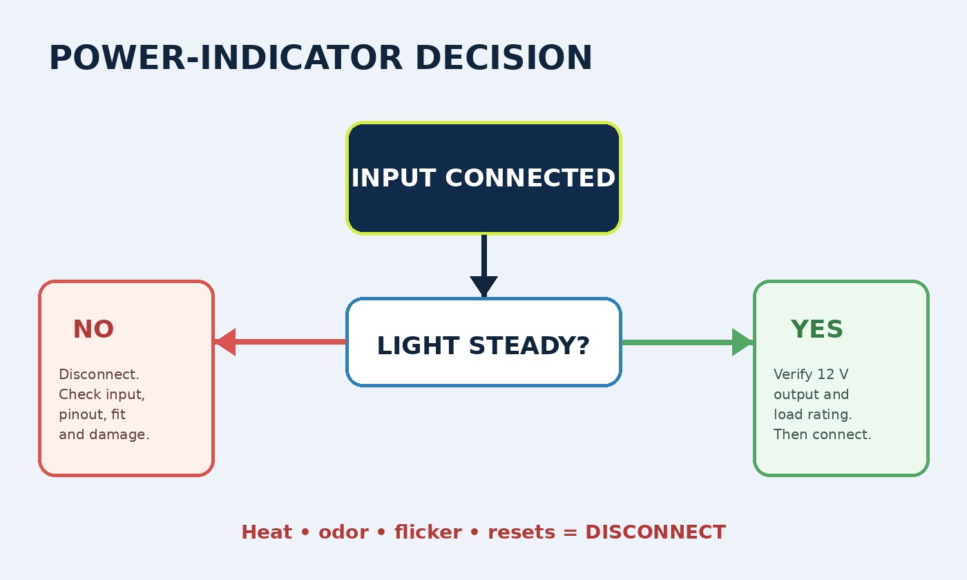
A steady indicator confirms that the adapter is receiving input, not that every output parameter is correct. If service authorization and suitable test leads allow, measure the female output at the identified power and ground terminals and verify approximately 12 V with correct polarity before connecting the tool. Never short adjacent pins with a probe. If the indicator is off, flickers or the output is unstable, unplug immediately and diagnose the 24 V supply, ground, pinout and connector fit.
8. Connect the 12 V diagnostic tool
With output verified, align the tool plug with the adapter’s female end marked Output Voltage: 12V. Insert it fully and provide strain relief. Power the tool according to its manual, then confirm a normal startup without resets, dimming or connection warnings. Check the adapter and both connectors for abnormal temperature during the first minute before beginning diagnosis.
Monitor during diagnosis
9. Change ignition state only as the procedure requires
After the tool powers normally, follow the vehicle and scan-tool instructions for key on, engine off or engine running. Do not assume a converter approved for reading codes is suitable for long programming sessions. Watch for display resets, communication dropouts or indicator flicker when ignition state changes; these can reveal input drop, overload, poor terminal contact or converter protection.
10. Keep the converter cool and unloaded
Place the housing in free air rather than under carpet, trim or clothing. Do not leave it in direct sunlight or against hot components. Periodically touch only the insulated case to check for abnormal heating. Warmth can occur during conversion, but rapid temperature rise, softening plastic, odor or discoloration requires immediate shutdown. Do not add a splitter or second device unless the combined peak load and pinout are explicitly within rating.
Record the configuration before repeated use
For a fleet or workshop, record the vehicle model, diagnostic-connector voltage and pinout, adapter identification, verified output rating, scan-tool model, tool peak demand and the key states tested. A converter that works with one interface is not automatically approved for another interface with a different wireless module, display or battery. Retain the first-session input/output readings and any temperature observation so a later reset or communication dropout can be compared with a known baseline rather than dismissed as a software fault.
Requalify the combination after scan-tool hardware changes, vehicle harness repairs, connector replacement or visible adapter damage. If the output is near 12 V with no load but falls after the tool starts, measure the 24 V input and ground under the same condition using the approved procedure. A stable input with a falling output points toward converter capacity, heat or failure; falling input points toward vehicle supply, fuse, terminal or ground resistance. This split prevents replacing a scan tool when the real fault is the power path. Never open the converter housing for diagnosis.
Disconnect safely
11. End the diagnostic session
Finish scan-tool operations and save reports, then follow the tool’s shutdown process. Turn ignition off and allow the vehicle state to settle. Disconnect the 12 V diagnostic device from the adapter first so the converter is unloaded. Grip the connector housing—not the cable—and pull straight.
12. Remove the adapter from the vehicle
After the tool is removed, unplug the adapter’s 24 V input from the vehicle. Inspect the power indicator extinguishes and check the housing and terminals for heat, odor, looseness or discoloration. Store the dry adapter with terminal protection where heavy tools cannot crush it. Do not leave it permanently installed unless MRCARTOOL and the vehicle maker explicitly allow that use; an energized converter can contribute to battery drain or heat.
Troubleshoot power problems
| Symptom | Check first |
|---|---|
| Indicator stays off | Remove adapter; verify vehicle 24 V power/ground pins, fuse, key state and connector seating |
| Indicator lights but no 12 V output | Disconnect tool; verify output with an authorized method and remove a faulty adapter from service |
| Tool starts then resets | Peak tool load, missing adapter rating, input voltage drop, poor ground or overheat protection |
| Tool powers but cannot communicate | Protocol, pin assignment and vehicle coverage; voltage conversion does not translate data |
| Connector will not seat | Wrong connector/keying, bent pin, obstruction or pushed-back terminal—never force it |
| Case becomes hot | Unplug immediately; check overload, ventilation, ambient heat and connector resistance |
| Communication drops with ignition change | Input sag, current surge, loose terminal or converter protection |
| Need module programming | Use the OEM-approved interface and regulated programming supply, not an unrated converter path |
Final adapter checklist
- Vehicle diagnostic connector verified as the correct 24 V input and pinout
- Diagnostic device verified for 12 V input and vehicle communication protocol
- Device peak demand below a documented adapter current/power rating
- Programming, starting, battery support and high-power loads excluded
- Ignition and tool off before connection
- Housing, male pins, female terminals and vehicle port undamaged
- 24 V male input connected to vehicle first
- Power indicator steady and 12 V output/polarity verified when authorized
- 12 V diagnostic tool connected only after output proof
- Adapter supported away from pedals, water, sun and heat
- No flicker, resets, odor, discoloration or abnormal temperature
- Tool disconnected before adapter is removed from vehicle
- Adapter unplugged after use and inspected before storage
The adapter solves one narrow problem: it lowers a verified 24 V OBD power feed to 12 V for a separately compatible low-power device. The safest workflow is therefore a chain of proofs—vehicle voltage and pinout, tool voltage and protocol, documented load capacity, correct direction, stable indicator and cool operation. If any link is unknown, do not let the plug-and-play shape substitute for an electrical specification.











Comments 0
Questions, fixes, and real-world diagnostic notes from readers.
Be the first to share a diagnostic result or ask a follow-up question.