
How to Use the AUTOOL CT150 Fuel Injector Cleaner and Tester

The AUTOOL CT150 works best as a controlled comparison bench: keep each injector in a numbered position, clean all four with the same process, then repeat the same leak, spray-pattern, and flow tests with the same test fluid, pressure, pulse width, mode, and run time. That matched before-and-after comparison is more useful than a single measuring-cylinder reading.
The CT150 is designed to clean and bench-test up to four compatible standard 12 V gasoline injectors. It can ultrasonically clean diesel injectors, but it cannot test them, and it is not a GDI high-pressure injector bench. The CT150 also has no ultrasonic-heating function; do not mistake CT160 instructions for CT150 controls.
In this guide
- The safe CT150 workflow at a glance
- What the CT150 can—and cannot—tell you
- Before you start
- Know the parts you will use
- Step-by-step: clean the injectors
- Step-by-step: mount and test the injectors
- Compare the result without overdiagnosing
- Shut down, drain, and store the CT150
- CT150 troubleshooting boundaries
- Frequently asked questions
- The repeatable comparison is the real result
The safe CT150 workflow at a glance
Use this sequence:
- Confirm injector compatibility, the machine’s input voltage, the correct adapters, and the fluid instructions.
- Relieve vehicle fuel pressure and remove the injectors under the vehicle maker’s service procedure.
- Label each injector by cylinder, inspect the body and seals, and remove loose exterior dirt.
- Put approved cleaning liquid in the ultrasonic tank, keep electrical connectors above the liquid, connect the drive leads, and run ultrasonic cleaning without heat.
- Drain or recover the cleaning liquid as its instructions require.
- Mount the injectors securely on the test rail and plug every unused position.
- Add approved injector test fluid to the test circuit—not cleaning liquid.
- Run leakage, spray-pattern, and flow comparisons at settings appropriate for the injector.
- Repeat the same test settings after cleaning, record the result, then depressurize, drain, and store the machine correctly.
Stop if an injector or adapter leaks, the rail will not clamp squarely, the pressure behaves abnormally, a measuring cylinder is damaged, the machine smells hot, or fluid reaches an electrical connection.
What the CT150 can—and cannot—tell you
The four measuring cylinders let you compare injectors side by side. A useful CT150 test can reveal a dripping injector, a visibly distorted spray, a restricted injector, or a flow imbalance within the tested set. The operating modes can also simulate different pulse conditions so you can check whether the relative result remains consistent.
The bench result does not identify every cause of a vehicle fault. If all four injectors appear weak, first recheck the test setup, fluid, pressure, adapters, electrical connections, and selected function. On the vehicle, fuel-supply pressure, wiring, driver control, intake leakage, ignition, compression, and mechanical condition can produce similar symptoms.
Keep the injector order. “Cylinder 2 before cleaning” must still be “Cylinder 2 after cleaning,” or the comparison loses diagnostic value.
Before you start
Confirm the exact machine and injector type
Read the nameplate and delivered manual before filling either circuit. Confirm the voltage and plug version, then verify that the injector is a compatible standard gasoline type and that the correct upper and lower adapters are available. If you need to service GDI or another high-pressure injector, use a bench specifically approved for it.
The AUTOOL CT150 product page can help identify the current four-position configuration. Use the delivered machine, serial-specific documents, injector data, and vehicle service information to make the final compatibility decision.
Prepare a safe work area
Work on a stable, level bench in a well-ventilated area away from flames, sparks, hot work, and smoking. Wear eye protection and fluid-resistant gloves specified by the liquid supplier. Keep absorbent material and the liquid safety data sheets available. Do not use gasoline, kerosene, or an unapproved flammable substitute in the machine.
The measuring cylinders are glass. Do not operate with a chipped or cracked cylinder, and do not lean over the rail while the test circuit is pressurized.
Keep the two liquids separate
The ultrasonic tank and test circuit do different jobs:
- Ultrasonic cleaning liquid belongs in the open cleaning tank. Use a product approved for injector cleaning and compatible with the tank, injector materials, and seals.
- Injector test fluid belongs in the machine’s test-fluid circuit. It provides the controlled liquid for pressure, leakage, spray, and volume checks.
Never pour cleaning liquid into the test circuit. Do not mix the recovered liquids, and do not run the ultrasonic tank dry.
Record a repeatable baseline
If the injectors can be tested safely before cleaning, record their positions, the test fluid, pressure, pulse width, selected mode, run time or injection count, visible spray pattern, leakage result, and cylinder level. If contamination makes a safe baseline impossible, document that fact and begin with cleaning.
Do not copy one universal pressure value from a generic tutorial. Use the current injector or vehicle specification and the limits in the delivered CT150 instructions. The available CT150 documents contain inconsistent general parameter values, so injector-specific data should control the setting.
Know the parts you will use
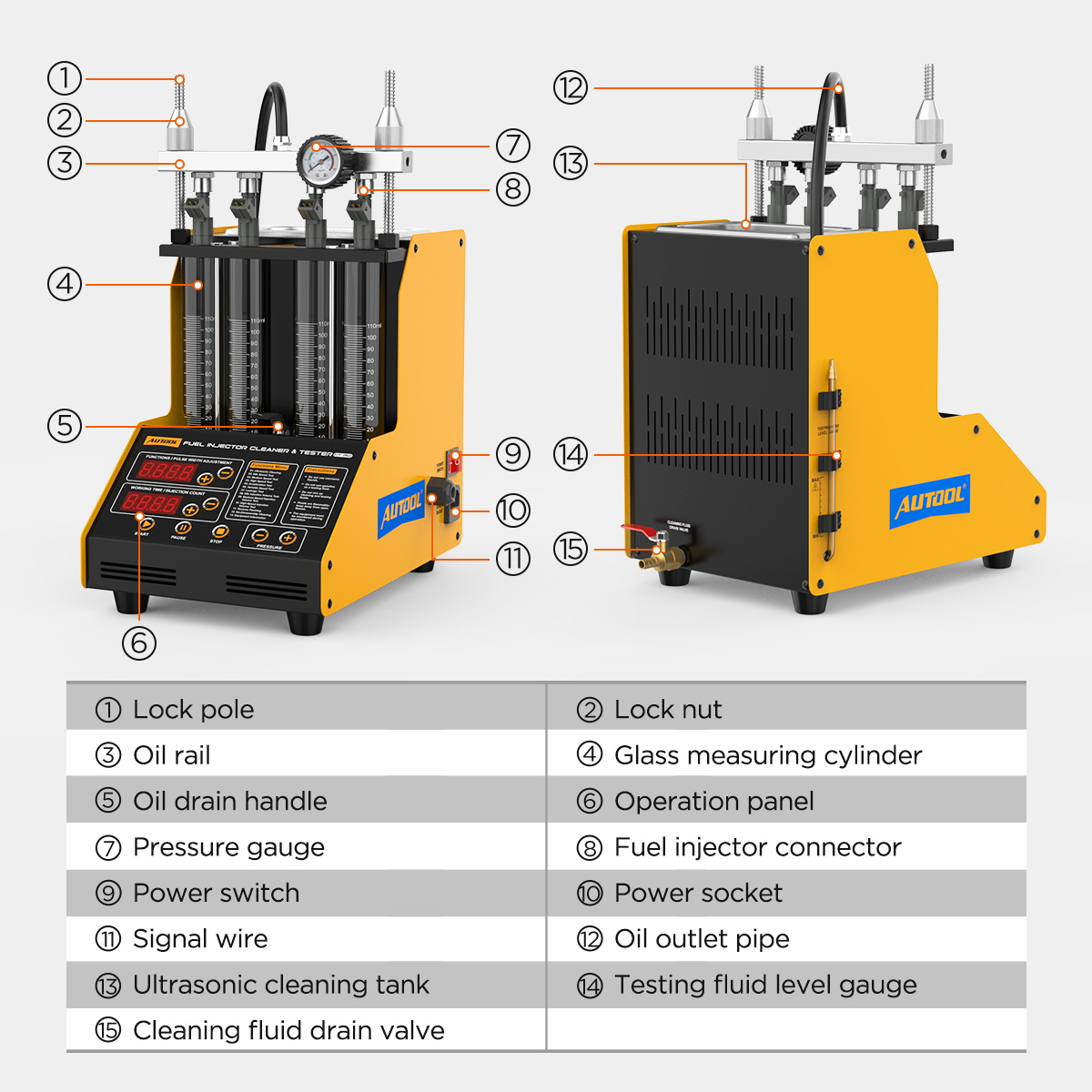
For the normal clean-and-test cycle, identify the ultrasonic tank, cleaning-fluid drain, test-fluid filler and level window, test-fluid outlet/drain, four measuring cylinders, rail and locking hardware, pressure gauge, injector signal leads, function selector, time or injection-count controls, pulse-width controls, pressure controls, and START, PAUSE, and STOP keys.
Do not infer a hidden fluid path from a product photo. Follow the labels on the delivered machine. If a valve, hose, or panel label differs from the current manual, stop and obtain the correct instructions for that unit.
Some translated CT150 labels use the word “oil” for parts of the test-fluid circuit. That wording does not mean engine oil. Fill the circuit only with approved injector test fluid.
Step-by-step: clean the injectors
Step 1: Remove and identify the injectors correctly
Relieve fuel-system pressure and disconnect power as the vehicle maker specifies. Remove the rail and injectors without forcing connectors or sealing surfaces. Cap open vehicle fuel lines, then label every injector by its original cylinder.
Completion check: Each injector has a durable position label, open vehicle lines are protected, and no fuel remains where it can reach an ignition source.
Common mistake: Mixing the injectors after removal. A clean result without cylinder identity cannot be compared reliably with the original fault.
Step 2: Inspect the injector and seals
Remove loose exterior dirt before the injector enters the bath. Inspect the body, electrical connector, inlet screen, pintle or nozzle area, and all O-rings. Replace a cut, hardened, swollen, or missing seal with the correct part before pressurizing the test setup.
Do not continue with a cracked body, loose electrical terminal, severely corroded component, or damaged sealing land.
Completion check: The exterior is clean enough not to contaminate the bath, and every pressure seal and adapter surface is serviceable.
Step 3: Set the injectors in the ultrasonic tank
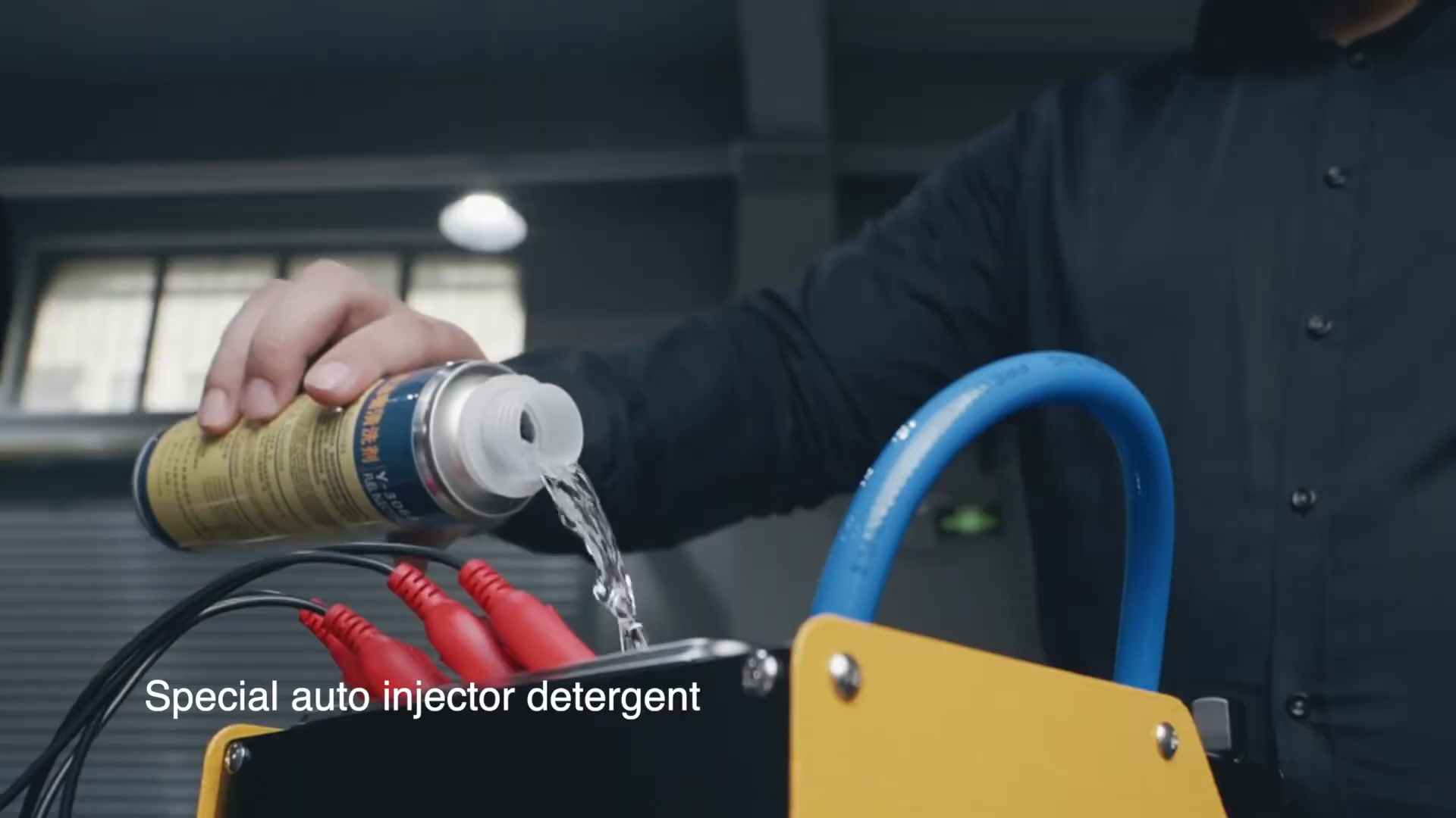
Place the cleaning rack in the tank and position the injectors so the working ends can be cleaned while the electrical pulse connectors stay above the liquid. Connect the matching CT150 drive leads, using the correct adapter leads when required. Keep the clips separated and fully seated.
Add the approved ultrasonic cleaning liquid before starting. Use enough to cover the intended cleaning area without submerging electrical connectors or overflowing the tank.
Completion check: The injectors are stable, connectors remain dry, the correct leads are attached, and the tank contains the approved liquid.
Stop: Do not start a dry tank or use the tank if liquid can reach a damaged cable, connector, switch, or power inlet.
Step 4: Run ultrasonic cleaning—without heat
Power the machine, select the CT150 ultrasonic-cleaning function, set the time according to the delivered manual and liquid instructions, then start the injector pulse and ultrasonic action as required by the panel. The CT150 does not heat the cleaning liquid. Do not add a heater or follow CT160 heating directions.
Observe the tank throughout the cycle. The injectors should remain positioned, the liquid should stay below the electrical connections, and the machine should operate without abnormal noise, odor, smoke, or leakage.
Completion check: The selected cycle ends normally and the injectors remain safely positioned.
Common mistake: Treating a longer cycle or stronger liquid as automatically better. Excessive exposure can damage incompatible plastics, coatings, filters, or seals.
Step 5: Finish the cleaning stage
Stop the machine before touching the leads or injectors. Remove the injectors carefully, allow them to drain over the tank, and wipe the exterior with a compatible lint-free material. Drain, recover, filter, store, or dispose of the cleaning liquid according to its condition, label, safety data sheet, and local rules.
Keep this liquid out of the test-fluid reservoir.
Step-by-step: mount and test the injectors
Step 6: Install the injectors on the test rail
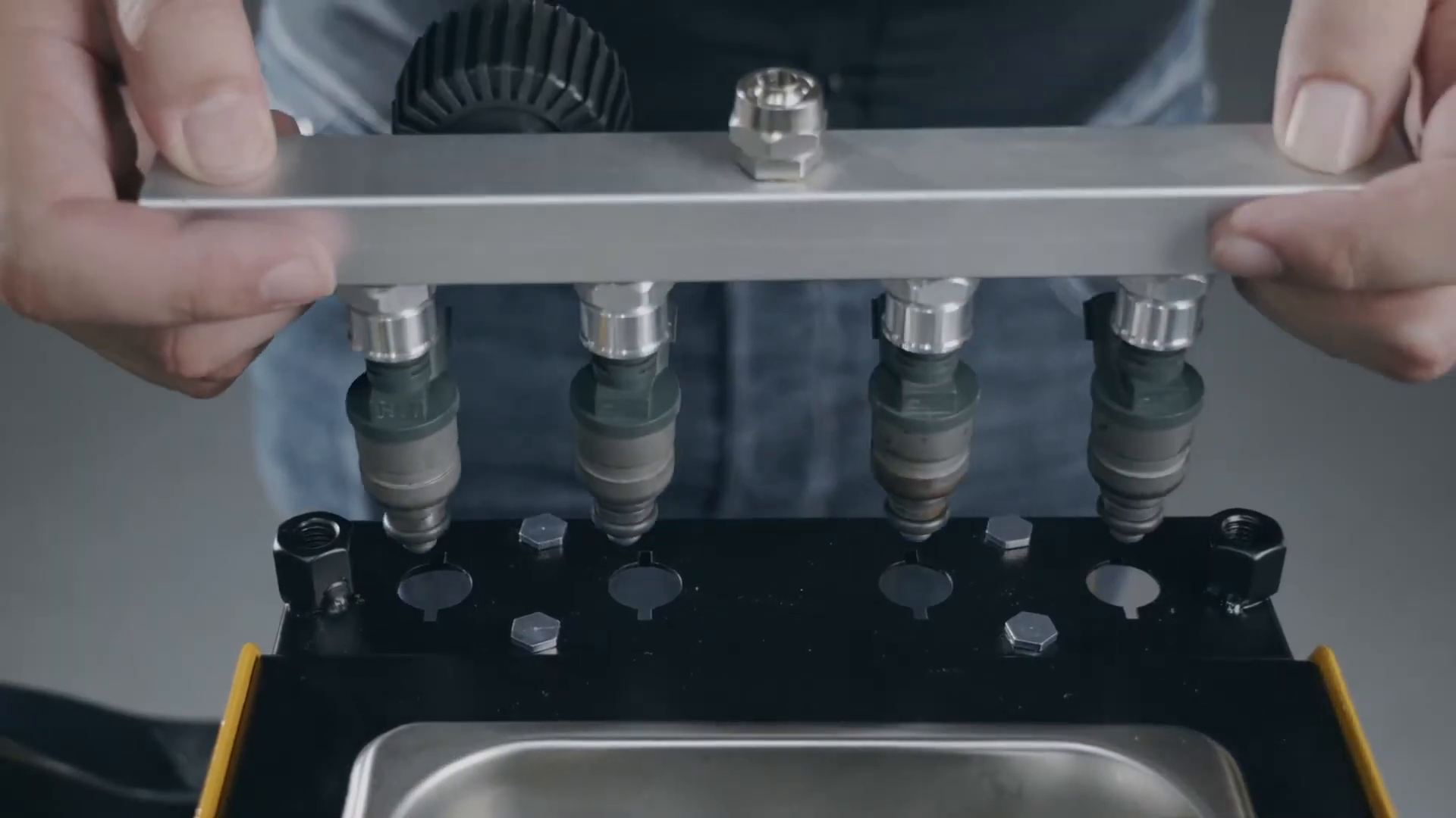
Select the correct adapters for the injector inlet and outlet shape. Lightly lubricate new O-rings only with a compatible assembly lubricant. Seat each injector straight in its numbered position, place the upper rail squarely over the set, then tighten the locking hardware evenly. Plug every unused rail outlet with the specified blanking hardware.
Connect each signal lead to the corresponding injector. A connector should lock without stretching the wire or loading the injector sideways.
Completion check: All injectors are vertical, equally seated, correctly numbered, electrically connected, and clamped without a visible seal gap.
Stop: Do not pressurize a crooked injector, damaged O-ring, mismatched adapter, loose blanking plug, or rail that will not sit parallel.
Step 7: Add dedicated test fluid
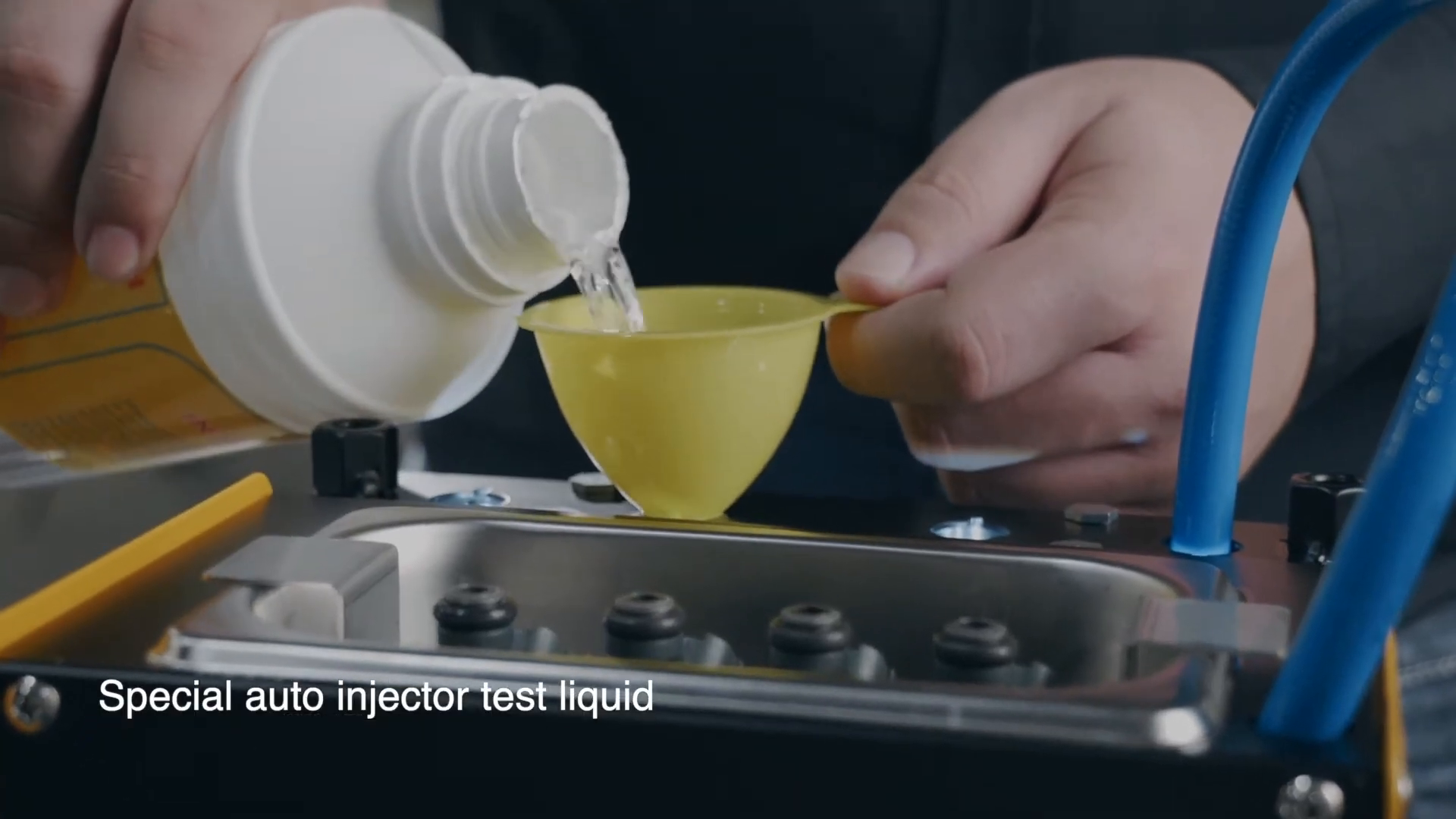
With the machine stopped and the test circuit unpressurized, use a clean funnel to add only the approved injector test fluid at the designated filler. Check the test-fluid level window on the delivered unit. Close the filler and verify that the drain and recycling valves are in the correct operating position.
Completion check: The test circuit contains clean approved test fluid, no liquid is spilled near electrical parts, and the ultrasonic cleaning liquid remains separate.
Step 8: Set pressure and test conditions
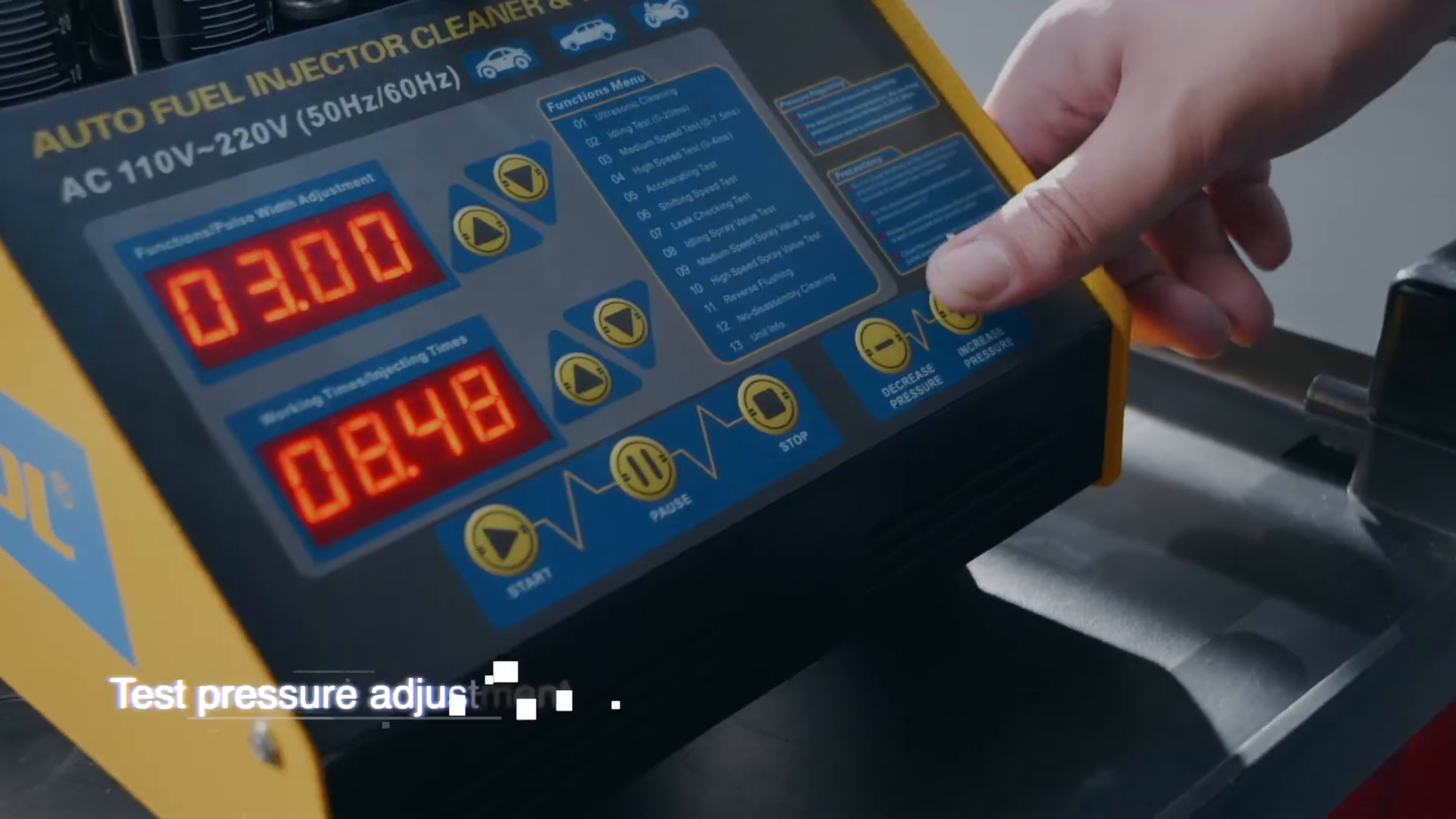
Select the required function, then set pressure, pulse width, time, or injection count from the injector specification and the current CT150 instructions. Start at the appropriate controlled setting for that injector; never exceed the injector, adapter, hose, gauge, or machine limit.
For comparisons, keep all variables unchanged: injector position, test fluid, pressure, pulse width, mode, time or injection count, and measuring-cylinder starting level. Change only one variable when you intentionally investigate its effect.
Completion check: The settings are recorded and suitable for the exact injector, and the pressure holds steadily without an external leak.
Step 9: Run the leakage check first
Choose the leakage function and pressurize the mounted set without commanding a normal spray cycle. Watch each nozzle and every rail, adapter, plug, and O-ring joint.
A droplet at the nozzle can indicate an injector sealing problem. Wetness at an adapter or rail joint is a setup leak, not an injector diagnosis.
Completion check: No external joint leaks, and each injector’s nozzle result is recorded separately.
Stop: Press STOP and release pressure under the delivered instructions if any adapter, hose, plug, rail joint, or injector seal leaks.
Step 10: Compare spray patterns
Select an appropriate idle, medium-speed, high-speed, acceleration, or spray-volume function. Start the cycle and observe from the front and side without placing your face or hands over the rail. Compare cone shape, direction, atomization, pulsing consistency, and shutoff behavior across all installed injectors.
Look for a split, deflected, coarse, intermittent, or dribbling pattern. Do not decide from one instant; repeat the same controlled mode if the first view is unclear.
Completion check: Every injector has a recorded pattern under the same test conditions.
Step 11: Compare flow volume
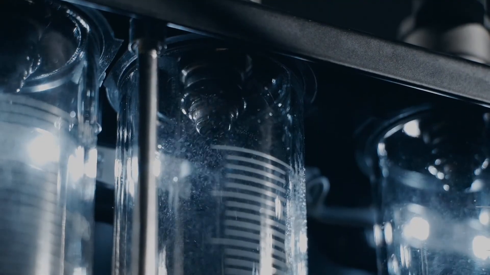
Drain or equalize the measuring cylinders as the delivered procedure requires, then run the chosen volume test for the same time or injection count. Let the cylinders settle before reading at eye level. Record each result rather than relying on memory.
The key result is relative balance under matched conditions. Do not apply an unsupported universal percentage threshold. Use the injector maker’s specification, the vehicle service information, and repeatability of the test.
Completion check: All four readings come from one matched run and can be traced to the injector positions and settings.
Step 12: Use reverse flushing only when compatible
Reverse flushing can move contamination away from the inlet screen, but the injector, adapters, seals, and delivered CT150 setup must support the reversed installation. Follow the exact orientation and blanking arrangement in the current manual. Never improvise a hose connection or hold an injector by hand under pressure.
After reverse flushing, reinstall the injector in the normal direction and repeat leakage, spray, and flow checks.
Compare the result without overdiagnosing
Use the same settings for the final test that you used for the baseline. A useful record includes injector number, before/after leakage, before/after spray description, before/after volume, pressure, pulse width, mode, run time or count, test fluid, and date.
Interpret the pattern conservatively:
| Result | What it suggests | Best next check |
|---|---|---|
| One injector improves and the set becomes more even | Deposits likely contributed to the imbalance | Repeat once for consistency, then reinstall with correct seals and vehicle procedure |
| One injector still drips or stays visibly different | Persistent injector restriction, wear, or damage is possible | Swap test positions to rule out a channel or adapter issue; repeat, then refer or replace as specifications require |
| All injectors show a similar poor result | A common setup or supply problem may be affecting the test | Recheck fluid, pressure, function, pulse settings, connectors, filters, and rail sealing |
| Bench balance is good but the vehicle symptom remains | The root cause may be outside the injectors | Check vehicle fuel pressure, control signals, wiring, ignition, compression, intake leakage, and mechanical condition |
Swapping two injectors between test positions is a strong cross-check. If the abnormal result follows the injector, suspicion stays with the injector. If it remains in one machine position, inspect the adapter, seal, lead, channel, and setup before condemning a part.
Shut down, drain, and store the CT150
Press STOP, return the test circuit to a safe unpressurized state under the delivered instructions, then switch off and unplug the machine before disconnecting injectors or opening the fluid system. Drain the measuring cylinders and test circuit only into a correctly labeled container. Keep used test fluid separate from ultrasonic cleaning liquid.
Wipe spills promptly with materials compatible with the fluid. Clean the tank and exposed fittings, inspect the O-rings and adapters, and store small parts in labeled groups. Leave the rail, cylinders, cables, and power inlet clean, dry, and protected from impact.
Do not store the CT150 with pressure trapped in the rail, a cracked cylinder, a leaking hose, contaminated fluid, or a reported electrical fault.
CT150 troubleshooting boundaries
- Pressure will not build: Stop and check test-fluid level, valve positions, rail plugs, adapters, seals, and visible external leaks. Do not open the pump or electrical enclosure.
- One cylinder reads differently every time: Repeat with matched settings, check for bubbles or leakage, then swap injector positions to separate injector behavior from a test-channel problem.
- An injector does not pulse: Stop, inspect the connector and approved adapter lead, and swap a known-good channel only if the delivered procedure permits it. Do not apply battery voltage directly unless the injector maker specifies the method and current control.
- The ultrasonic tank does not operate normally: Confirm that approved liquid is present and the correct function is selected. Stop for abnormal sound, heat, odor, smoke, or a dry tank.
- Fluid reaches electrical parts: Disconnect power only when it is safe to do so, keep the machine out of service, and have it inspected before reuse.
Frequently asked questions
Can the CT150 test diesel injectors?
No. The current CT150 information allows ultrasonic cleaning of diesel injectors but does not support diesel injector testing.
Does the CT150 heat the ultrasonic bath?
No. CT150 has ultrasonic cleaning without heating. CT160 is the related four-position model with a heating function.
Can cleaning liquid be used as test fluid?
No. Cleaning liquid and test fluid belong in separate circuits and are not interchangeable.
What pressure should I use?
Use the current specification for the exact injector and stay within the delivered CT150, adapter, and hose limits. Do not assume one generic number applies to every gasoline injector.
Where can I get the current manual?
Use the AUTOOL manual download center and select CT150. Match the manual to the model, voltage version, panel, and delivered accessories before operating.
The repeatable comparison is the real result
A good CT150 session ends with more than clean injectors. It produces a traceable answer: each injector stayed in a known position; cleaning and test liquids remained separate; the rail passed its leak check; every spray and volume comparison used matched settings; and the final result was checked against the injector and vehicle specifications.
If the setup, compatibility, pressure source, adapter seal, or delivered instructions remain uncertain, pause the test. Correcting the test condition is faster—and safer—than replacing an injector on the strength of a misleading result.











Comments 0
Questions, fixes, and real-world diagnostic notes from readers.
Be the first to share a diagnostic result or ask a follow-up question.