
How to Use the AUTOOL PT610 Pressure Tester

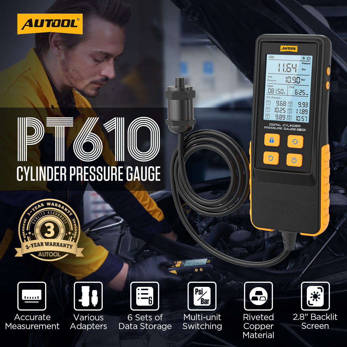
The AUTOOL PT610 is an automotive pressure tester. This guide turns the current model-specific controls and official operating sequence into a practical start-to-finish workflow.
Quick answer: Identify the exact PT610, inspect every connection, prepare the permitted vehicle test point, follow the model’s sequence below, and treat the result as one piece of diagnosis—not as permission to skip the vehicle service procedure.
In this guide
Before you start
Work in a clean, well-lit and ventilated area. Stabilize the vehicle, keep rotating or hot components out of the work zone, and open the exact vehicle procedure for the system and test point you will use. A tool connection is not automatically safe just because an adapter fits.
- confirm that the model label reads AUTOOL PT610 and that the controls match this guide;
- inspect the housing, cables, clamps, hoses, fittings, seals and adapters for damage or contamination;
- identify the permitted connection point, test range, vehicle state and acceptance criteria before connecting;
- keep eye protection and the task-appropriate gloves within reach; and
- plan how you will return the vehicle circuit or line to its original sealed condition after the test.
Use the AUTOOL manual download center to locate the current instructions when a manual is available. The delivered model label and current vehicle service information control if an older image or remembered setting differs.
PT610 controls and specifications
| Specification or function | Current model |
|---|---|
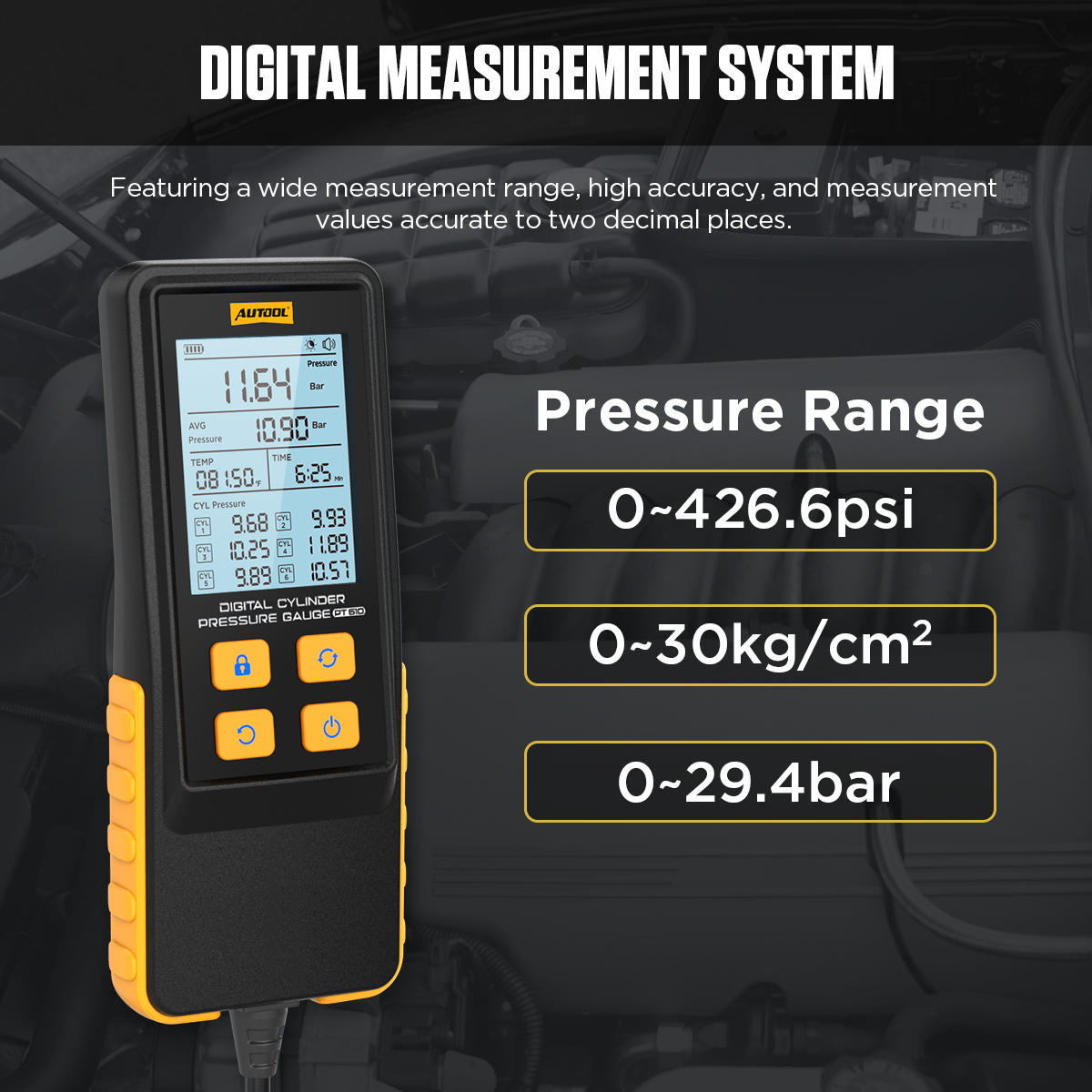
| Pressure Range | 0-426.6 PSI / 0-29.4 Bar / 0-30 kg/cm² |
| Product | AUTOOL PT610 Digital Cylinder Pressure Gauge |
| Main Application | Engine cylinder compression pressure testing |
| Display Resolution | 0.01 |
| Pressure Units | PSI, Bar, kg/cm² |
| Temperature Units | °C and °F |
| Screen | 2.8-inch HD backlit display |
| Displayed Data | Real-time pressure value, average pressure value, current temperature, measuring time, and cylinder pressure values |
| Data Storage | Up to 6 sets of cylinder pressure data |
| Data Functions | Save cylinder data, lock interface, clear interface data, and pressure zeroing |
Stay inside both limits: the tool’s rated range and the vehicle or component’s permitted test range. When they differ, the lower applicable limit is the boundary. Do not infer a missing gauge, adjustment, mode or protection feature from a higher model in the same series.
How to use the PT610
Step 1: Confirm the pressure type, range and test point
Identify whether the target is vacuum, differential, cylinder, oil, fuel, transmission, brake or suspension pressure. Confirm that the exact tool range, medium and adapter are permitted at the chosen vehicle test point.
Before moving on, pause and check the connection against the physical labels. A secure-looking connection can still be the wrong port, polarity, range or adapter.
Step 2: Inspect and assemble the measurement path
With the vehicle in the safe state required by its service procedure, inspect the sensor, hose, cable, fittings and seals. Fit only the exact adapter and route the line away from heat, belts, fans and sharp edges.
Step 3: Connect with no unintended pressure applied
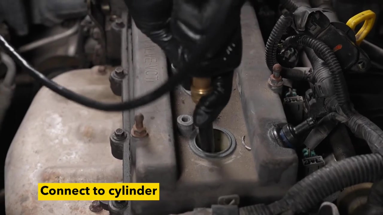
Attach the measurement side securely before applying power, vacuum or pressure. For a two-port differential gauge, confirm the high and low ports; for a single-port gauge, cap or leave unused ports exactly as the current instructions specify.
Step 4: Power on and establish the reference
Power the gauge as marked and let the display stabilize with the measurement path in the required reference condition. Use a zero or tare function only when the exact model provides it and the instructions call for it.
Step 5: Create the vehicle-specified test condition
Start, run, actuate or load the system only as the exact vehicle procedure requires. Watch the connection continuously and stop if a hose moves, a fitting leaks, the range is exceeded or the reading behaves abnormally.
Step 6: Record a stable reading and compare correctly
Record the unit, test condition and stable value—not just a peak glimpsed during transition. Compare it with the specification for that vehicle, engine, system temperature and operating state.
Step 7: Return to zero, disconnect and restore
Shut the system down and release pressure or vacuum by the approved method. Confirm a safe state before loosening the adapter, then restore the original plug, line or fitting and check for leaks or warnings.
Do not end the job at the first plausible indication. Repeat or confirm the observation under the same controlled condition, then restore the vehicle connection and check for leakage, warnings or an abnormal response.
Read and verify the result
Compare the observation with known conditions, not with a single memorized number. Check whether the reading, indication or visible result is stable, repeatable and produced with the correct setup. If possible, compare a known-good point or repeat after correcting one controlled variable.
- A repeatable result at the correct connection is stronger evidence than a momentary spike or one brief indication.
- An out-of-range result can identify a direction for diagnosis, but it does not name the failed component by itself.
- A normal result at one test point does not clear every part of the system; follow the vehicle diagnostic tree.
- After a repair, repeat the same controlled test and complete the vehicle-specific functional check.
Stop the test if the connection leaks, a cable or hose heats, the tool reports a fault, the reading is unstable for an unexplained reason, or the vehicle behaves abnormally. Remove power or pressure using the model’s shutdown sequence before changing the setup.
Common mistakes and care
- Use the adapter that matches the cylinder test port before measurement.
- Reset the pressure value to zero before each new test.
- Use the quick-release valve button for fast pressure release after testing.
- Save up to 6 cylinder pressure results when cylinder-by-cylinder comparison is needed.
- Do not borrow a range, mode, connection order or interpretation rule from another model in the series.
- Do not disconnect a live electrical, pressure, vacuum or fluid connection; first return the tool and vehicle system to a safe state.
- After use, clean only as directed, keep ports capped, coil leads and hoses without sharp bends, and store the kit dry.
Frequently asked questions
Can I use the PT610 setup from a different AUTOOL model?
No. Similar housings and accessories do not prove identical ranges, controls, power requirements or connection methods. Match the exact model first.
Does one normal result prove the system is fault-free?
No. It proves only that the tested condition was within the chosen acceptance criteria at that moment. Continue the vehicle-specific diagnostic path when the symptom remains.
What should I do when the reading is unstable?
Stop and check power, connection security, sealing, range selection, test-point suitability and vehicle state. Repeat only after the cause of instability is understood.
Final PT610 checklist
- Exact model, permitted test point and test range confirmed
- Tool, leads, hoses, seals and adapters inspected
- Setup completed in the model-specific sequence
- Observation repeated or otherwise verified
- Vehicle connection restored with no leaks, loose terminals or open ports
- Tool shut down, cleaned and stored without trapped pressure or unsafe power
Used this way, the PT610 supports a disciplined diagnostic decision: prepare the correct test, control the setup, verify the observation and leave the vehicle in a known safe state.











Comments 0
Questions, fixes, and real-world diagnostic notes from readers.
Be the first to share a diagnostic result or ask a follow-up question.