
How to Use the AUTOOL LM130 Smart Digital Manifold

Use the AUTOOL LM130 by defining the exact A/C test, inspecting the one-knob flow path and hoses, connecting its temperature probe before startup, installing four AAA batteries, selecting one of the seven documented refrigerants and the required units, and zeroing the disconnected pressure path at atmosphere. Connect through the vehicle service procedure, then use Refrigeration, Evacuation or Pressure Leak Test mode only for the job each screen is designed to measure.
The LM130 is a compact smart digital refrigerant gauge with one external pipe-temperature probe, a sight window, refrigeration mode, relative-vacuum monitoring, a timed pressure-change test and an interface that can accept LM100 vacuum-gauge data. It cannot identify unknown refrigerant, choose a vehicle charge mass or turn one pressure reading into a complete diagnosis.
In this guide
What the LM130 measures
The AUTOOL LM130 displays current gauge pressure and, when its clamp probe is connected correctly, one pipe temperature. After you select the correct refrigerant, Refrigeration mode also shows evaporation (EV) and condensation (CO) saturation references and an SH/SC field.
Its documented refrigerant list is R12, R410A, R407C, R404A, R22, R134A and R502. If the vehicle refrigerant is not in that list, do not select a near match. Use suitable equipment with the exact refrigerant data required by the service procedure.
Unlike a two-channel manifold, LM130 presents one current pressure path. Plan which service point and system state you are measuring. Do not compare readings captured at different times as though they were a simultaneous high-/low-side snapshot.
Before you start
Open the AUTOOL manual download center and match the LM130 manual and physical controls. Obtain the vehicle refrigerant, port map, operating condition, charge specification, evacuation target, test medium and acceptance limits from exact service information.
Inspect the actual package. The manual documents one clamp temperature probe and four AAA batteries. Confirm the delivered hoses, adapters and probe rather than assuming a bundle from a listing image.
Use ventilation, eye and hand protection, rated low-loss couplers and compliant recovery, evacuation and charging equipment. Keep the gauge, hose and probe lead clear of fans, belts, hot exhaust parts and electrical terminals.
Stop: Do not connect an unknown or contaminated refrigerant system, pressure-test with oxygen or unregulated shop air, exceed the lowest component rating, vent refrigerant to clear a hose, or open the rotary valve before tracing every port.
Understand the LM130 controls and ports
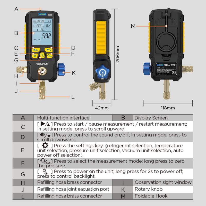
The front has a display, Start/Pause key, sound/down key, Settings key, Mode/Zero key and Power/Backlight key. The rotary knob controls the internal service path. The lower and side brass connections, sight window and filling/evacuation port must be traced against the exact connection diagram before use. The multi-function interface is also used when an LM100 provides more precise vacuum data.
LM130 step-by-step operating procedure
Step 1: Define one measurement task
Choose a current pressure-and-temperature observation, a procedure-controlled evacuation, or an isolated timed pressure-change test. Write down the refrigerant, chosen port, equipment connection, required system state, target values, duration and finish method.
Completion check: You can state what the single pressure channel represents and how the result will be accepted.
Step 2: Inspect the gauge, valve and pressure path
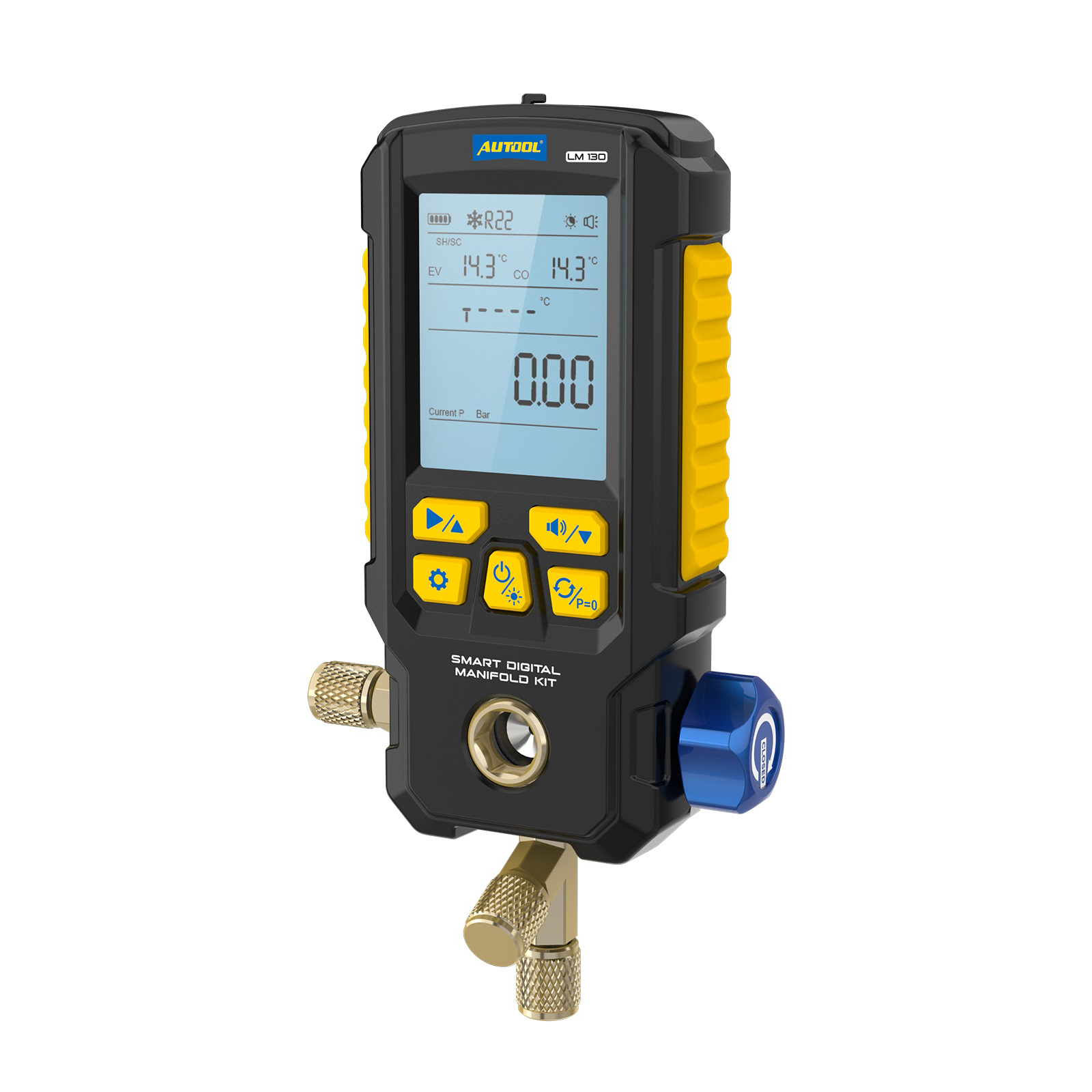
Turn the rotary valve to its closed position. Inspect the housing, screen, hook, sight window, multi-function connector, probe connector, brass threads, hoses, adapters, gaskets and valve stems. Replace damaged or contaminated components.
The gauge can measure up to 6 MPa, but its overload figure is not a working target and a standard hose can have a lower rating. The lowest-rated item controls.
Completion check: The complete path is clean, closed, compatible and rated for the job.
Step 3: Inventory the package and connect the probe
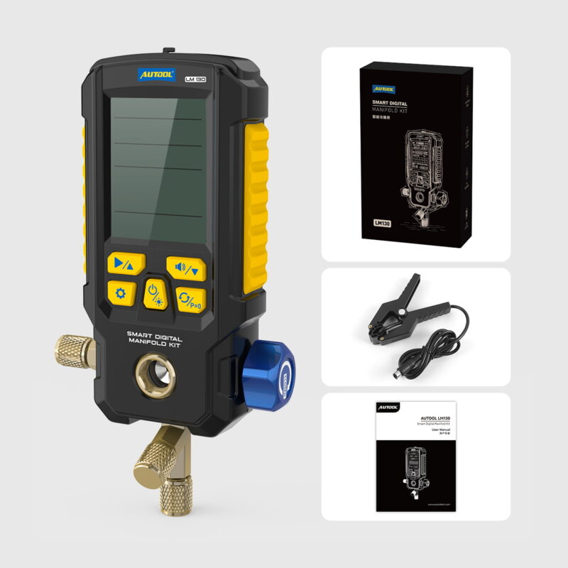
Identify the one temperature clamp, its connector and the hoses actually supplied. Check the clamp lead, jaw spring and sensor contact surface. Connect the probe before turning on the LM130; the manual requires this sequence for a temperature display.
Completion check: The probe connector is fully seated and its intended pipe location is written down.
Step 4: Install four AAA batteries and power on
Install four matched 1.5 V AAA batteries with correct polarity. Press Power, check the battery icon and screen segments, then test the backlight and keys. Configure auto-off long enough for the planned test.
Completion check: The display is stable and the battery state can support the complete measurement.
Step 5: Select the exact refrigerant and units
Enter Settings, then select the verified refrigerant, pressure unit, temperature unit and vacuum unit. The units cannot be changed while a measurement is running, so align them with the job sheet now.
Completion check: Refrigerant and every displayed unit match the written procedure.
Step 6: Zero the disconnected pressure path
Leave all pressure connections open to clean atmosphere with the rotary valve closed. Long-press Mode/Zero until P=0 completes and disappears. Never zero while a hose holds pressure or vacuum.
Completion check: The open-air pressure path reads zero before any service connection.
Step 7: Clamp the probe to the documented pipe
Attach the sensor to clean metal at the location required by the vehicle procedure, not over insulation, paint or a fitting. Ensure full jaw contact and route the lead away from heat and movement. Allow temperature to stabilize.
Completion check: The displayed temperature is stable and linked to one named pipe location.
Step 8: Hang the LM130 and trace the connection
Hang the instrument upright where you can see the display and sight window. Trace the measured service port, LM130 connection, hose, rotary valve and recovery/vacuum/charging destination end to end. Follow the vehicle and low-loss coupler instructions for connection order.
Stop: If the hose identity is uncertain, a coupler resists, a fitting leaks or the gauge was dropped, isolate the setup. The manual calls for hose replacement and technical evaluation after a damaging mechanical load.
Completion check: Every connection is identified and the rotary valve remains closed until the procedure calls for flow.
Step 9: Start Refrigeration mode under a defined condition
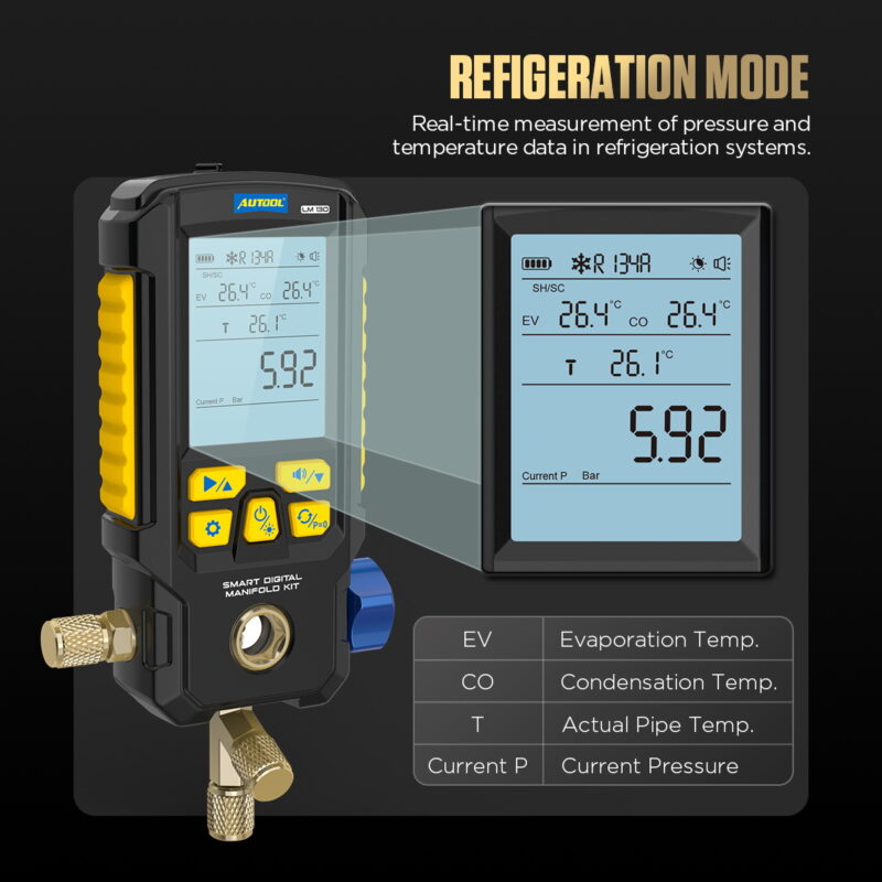
Select Refrigeration mode. Establish the exact engine speed, blower/load, doors, fan command and ambient measurement required by vehicle information. Press Start and wait for current pressure and pipe temperature to stabilize.
Completion check: The selected port, system state and ambient condition are recorded with the reading.
Step 10: Capture the complete refrigeration screen
Record current pressure, pipe temperature, EV, CO and the displayed SH/SC field at the same time. Interpret the calculated field only if the selected refrigerant, service port, pipe location and screen mode support it. A single probe and pressure channel do not provide the same evidence as simultaneous two-side measurements.
Completion check: Every displayed value has a known physical source and is compared with the exact vehicle procedure.
Step 11: Diagnose before moving refrigerant
Check airflow, fan operation, compressor command, clutch or variable-displacement control, sensor data, restrictions and the stability of the test condition. Do not add or remove refrigerant merely to make one pressure familiar. When service is justified, recover and charge by the specified process and mass.
Completion check: Setup and control causes are separated from an actual refrigerant-quantity decision.
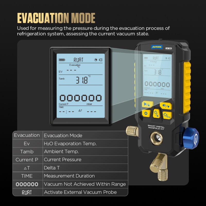
Step 12: Use Evacuation mode with the correct vacuum evidence
Recover refrigerant first, zero at atmosphere, connect the vacuum path as specified and enter Evacuation mode. Start the measurement and observe the relative pressure trend. When the procedure requires deep-vacuum acceptance, connect a clean LM100 or another approved absolute vacuum gauge at the correct system location and use its absolute reading and decay criterion.
Completion check: Evacuation acceptance comes from the required absolute target, stabilization and hold—not the LM130 relative reading alone.
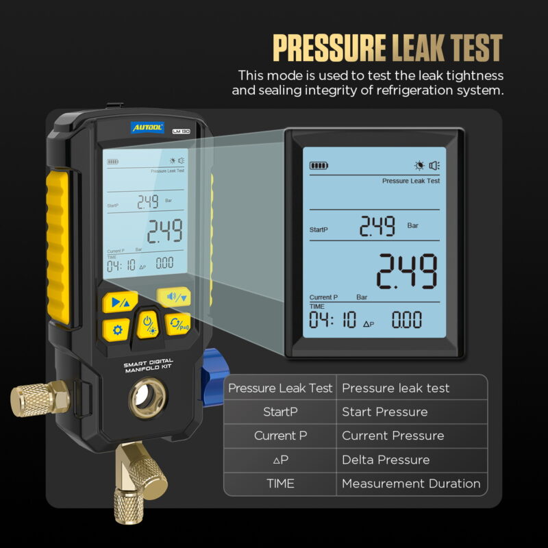
Step 13: Run Pressure Leak Test mode inside a defined test
Use only the specified test medium and regulated pressure. After stabilization, enter Pressure Leak Test and press Start. Record StartP, Current P, pressure difference, time and temperature. Stop, clear and repeat only after identifying why the previous condition was invalid.
Completion check: Medium, pressure, temperature, duration and pass/fail rule all match the exact procedure.
Step 14: Isolate, disconnect and store
Stop the measurement. Close the rotary valve and return the service equipment and vehicle to the required shutdown state. Manage trapped refrigerant through compliant recovery or low-loss equipment, disconnect in the prescribed order and restore service-port caps. Clean fittings and the probe surface, protect the connector and remove batteries for extended storage.
Completion check: No refrigerant was intentionally vented, ports are restored and the complete result is saved.
LM130 data-quality gates
| Gate | Pass condition | Stop or repeat when |
|---|---|---|
| Refrigerant | Exact refrigerant is one of the seven supported datasets | A near-match is selected |
| Zero | Pressure path is disconnected at atmosphere | A hose was pressurized during zeroing |
| Identity | Chosen service port and pipe location are recorded | One reading has no physical location |
| Condition | Load, airflow and compressor state are stable | Values come from changing conditions |
| Vacuum | Required absolute gauge and decay rule are used | Relative pressure is treated as micron acceptance |
Common LM130 problems
The temperature does not display
Power off, inspect the probe and connector, then connect the probe before restarting. Ensure the clamp has full metal contact. A damaged probe needs replacement, not an estimated value.
The pressure will not zero
Disconnect all pressure and vacuum sources, confirm the rotary valve position and release trapped pressure through approved equipment. Let the gauge stabilize before repeating zero.
SH/SC does not make sense
Recheck refrigerant selection, selected port, probe pipe location, contact and operating state. Do not use the field as a charging instruction when the measurement arrangement does not supply the required inputs.
Pressure changes during a retention test
Record temperature and inspect external hoses, adapters, gaskets and the rotary valve. A pressure trend does not identify a leak location by itself.
AUTOOL LM130 FAQ
How many refrigerants does LM130 support?
The manual lists seven: R12, R410A, R407C, R404A, R22, R134A and R502.
Can LM130 connect to LM100?
Yes. Its multi-function interface supports LM100 vacuum data so an evacuation can use more precise absolute-vacuum evidence.
What batteries does LM130 use?
Four 1.5 V AAA batteries.
Does LM130 measure high and low pressure simultaneously?
Its operating screen presents one current pressure channel. Define the connection and do not treat separate readings as a simultaneous dual-channel data set.
The reliable LM130 workflow
Define one task, inspect and close the flow path, connect the single probe before startup, install four AAA batteries, select an exact supported refrigerant and units, zero at atmosphere, map the service port and pipe location, capture the full Refrigeration screen under a stable condition, use absolute vacuum evidence when required, and run the timed pressure test only inside a defined procedure. Finish by isolating and disconnecting without venting. That keeps this compact gauge useful without asking one channel to answer a two-channel question.











Comments 0
Questions, fixes, and real-world diagnostic notes from readers.
Be the first to share a diagnostic result or ask a follow-up question.