
How to Use the AUTOOL AST618 Brake Fluid Exchanger

The AUTOOL AST618 brake fluid exchanger stores new brake fluid in the machine, sends it through one pressure output to a sealed reservoir adapter, and collects removed fluid in wheel-side recovery bottles. As a pressure brake bleeder, it controls the machine-side supply; it does not choose the vehicle-side procedure.
Prime the output away from the vehicle first. Then let the exact vehicle service procedure—not an accessory chart, displayed pressure, one-minute timer or wheel-order shortcut—control the fluid, pressure, service-point sequence and related vehicle decisions. It also controls the electronic state and completion checks.
Use one active service point by default. Four recovery bottles let you stage and observe several collection paths, but their presence does not prove that four bleeders may be opened together on every vehicle.
Close the active bleeder before pressing Stop/Relief. After Stop/Relief, wait at least 10 seconds, repeat the relief command if necessary, and confirm that the gauge remains at zero before touching any pressure-side connection.
Brake hydraulics are safety-critical. The operator must be able to support the vehicle safely, handle brake fluid and a 12 V battery connection, and follow exact bleeder specifications. The operator must also recognize an abnormal hydraulic result and keep an uncertain vehicle off the road. If the correct vehicle procedure, fluid, adapter or acceptance test is missing, stop before opening the system.
In this guide
- AST618 workflow at a glance
- What the AST618 controls—and what it does not
- Before you begin
- Phase A: qualify, identify and inspect
- Phase B: fill and prime the AST618 supply path
- Phase C: seal the reservoir, stage recovery and service each point
- Phase D: prove zero, drain the machine and release only a verified vehicle
- Interrupted-cycle recovery
- Troubleshooting after isolation
- AST618 care after the job
- Frequently asked questions
- Final AST618 checklist
AST618 workflow at a glance
Follow this dependency order:
- approve the exact vehicle, repair state and current service procedure;
- identify the current AST618 and its Pressure, Pulse, Time, Start/Pause and Stop/Relief controls;
- prepare the work area, safe vehicle support, correct new fluid, exact adapter, PPE, tools and waste containers;
- inspect the machine, storage tank, output hose, couplers, gauge, power lead, seals and recovery equipment;
- add sufficient new fluid while keeping the filler and supply path clean;
- prime the output away from the vehicle into controlled capture until flow is stably air-free;
- press Stop/Relief, wait at least 10 seconds and prove stable zero before reconfiguring;
- install the exact reservoir adapter and prove a dry, stable boundary at a vehicle-permitted condition;
- stage the required recovery paths with every bleeder still closed;
- service and close each vehicle-prescribed point under continuous observation;
- close the final bleeder before Stop/Relief, wait and prove stable zero before disconnecting; and
- restore the reservoir, complete leak, pedal, warning and diagnostic checks, drain the machine correctly and release the vehicle only if every gate passes.
If any check fails, do not skip ahead. Close the active bleeder, press Stop/Relief, leave the pressure boundary assembled, wait and prove zero. Correct the cause, re-prime if air may have entered and return to the exact vehicle procedure.
What the AST618 controls—and what it does not
AST618 has an integrated new-fluid storage tank, one pressure output, a quick coupler and up to four passive wheel-side recovery bottles. Its panel has separate Pressure, Pulse and Time displays with plus and minus keys, Start/Pause, Stop/Relief and an analogue pressure gauge.
The machine supplies new fluid at the reservoir while removed fluid travels from an opened vehicle service point through a clear hose into a recovery bottle.
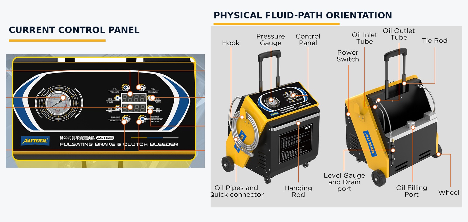
| Control or path | Its role | It cannot decide |
|---|---|---|
| Pressure controls and gauge | Adjust and observe machine outlet pressure within the permitted procedure | The safe pressure for a particular reservoir, adapter or brake system |
| Pulse controls | Change the machine’s pulsating delivery behavior | A universal pulse value or proof that the hydraulic circuit is complete |
| Time controls | Set an operating interval | The vehicle’s fluid, volume, color, bubble, diagnostic or acceptance endpoint |
| Start/Pause | Starts or pauses active fluid delivery | Whether every vehicle condition is safe to begin or resume |
| Stop/Relief | Stops delivery and commands pressure relief | Proof of zero pressure without observing the gauge |
| New-fluid storage tank | Holds the clean vehicle-specified supply | The job quantity, reserve or permission to mix fluids |
| One output hose and reservoir adapter | Carry new fluid into a sealed vehicle reservoir | Adapter fit, sealing condition or permitted vehicle pressure |
| Recovery bottles and clear hoses | Capture and help observe removed fluid | A universal wheel order, simultaneous-opening permission or completion by appearance alone |
AST618 cannot identify the correct vehicle fluid, prove adapter fit from a make list, select a safe pressure or choose a pulse and time setting for every vehicle. It cannot supply a generic ABS, EPB or brake-by-wire routine, specify a bleeder opening or torque, or decide that the vehicle is safe for road use.
The panel in front of you controls this guide. Instructions that refer to Vacuum, Fuel, acceleration or deceleration switches do not match this control layout. Do not infer functions from those terms or from a different AUTOOL model.
Before you begin
Open the exact current vehicle procedure. Identify every required service point, fluid specification, maximum permitted pressure and service order. Then identify the required ignition, engine, booster or pump state, scan-tool routine, bleeder method, tightening requirement, endpoint and final acceptance check. Confirm that pressure-assisted bleeding is allowed for the present repair state.
Do not treat a routine fluid exchange, a dry-system bleed and bleeding after a master cylinder, ABS hydraulic unit or line replacement as the same job. A dry or opened system may require bench bleeding, diagnostic activation, vacuum filling or another prescribed sequence that AST618 alone cannot replace.
Prepare:
- new, unopened brake fluid matching the exact vehicle specification;
- enough fluid for priming, the prescribed vehicle operation and a visible reserve;
- the exact clean reservoir adapter with an intact correct seal;
- exact-size bleeder tools, clear compatible hoses and labelled recovery containers;
- eye protection, fluid-compatible gloves, protective clothing and paint/spill protection;
- wheel restraints and approved lift/support equipment used by the vehicle procedure;
- a suitable intact 12 V DC source and safe battery access; and
- the fluid label/SDS plus a lawful used-fluid collection and disposal route.
Use the AUTOOL manual download center to match the instructions to the physical AST618 in front of you. The model label, delivered panel and exact vehicle information control whenever an old image or remembered sequence differs.
| Pre-start decision | What you must know | Stop when |
|---|---|---|
| Vehicle eligibility | Exact pressure-assisted method, system state and service order | The complete procedure is missing or does not permit the method |
| Brake fluid | Exact current specification and sufficient new supply | Fluid is old, opened, mixed, unknown or contaminated |
| Reservoir adapter | Exact geometry, attachment and sealing condition | The adapter is a near fit, damaged, forced or unable to seal stably |
| Electrical input | Delivered AST618 is marked for 12 V DC and polarity is known | Voltage, polarity, lead, clamps or battery access is uncertain |
| Initial brake condition | No unresolved leak, falling level, warning or unexplained abnormal pedal | Diagnosis or repair remains incomplete |
| Electronic routine | Required ABS, EPB, brake-by-wire or booster steps and tools are available | A generic ignition or scan-tool routine would have to be guessed |
| Final acceptance | Exact level, leak, pedal, warning, diagnostic and road-release criteria are known | “No bubbles” would be the only completion test |
Phase A: qualify, identify and inspect
Step 1: Approve the exact vehicle procedure
Record the vehicle identity and confirm that its current service information permits pressure-assisted bleeding for the present job. Identify the specified fluid, maximum allowed pressure, service-point order, and bleeder opening and tightening requirements. Then identify the required ignition, engine, booster or pump state, diagnostic activations, completion endpoint and final tests.
Inspect the vehicle before opening anything. A visible leak, damaged line, falling reservoir level, active brake warning, wrong or contaminated fluid, unexplained soft or sinking pedal, or uncertain repair state needs diagnosis. A routine exchange must not hide a fault.
If the system has run dry or a hydraulic component was replaced, follow every additional step in the vehicle procedure. Do not replace required bench bleeding, scan-tool activation or circuit-specific work with generic pedal pumping or a familiar wheel sequence.
Completion check: The exact current procedure supports pressure-assisted service and supplies every fluid, pressure, sequence, electronic and final-check decision required for this job.
Step 2: Confirm the current AST618
Read AST618 on the machine and match it to the delivered instructions. Identify the analogue gauge, Pressure, Pulse and Time displays, their plus and minus keys, Start/Pause, Stop/Relief, power switch, filler, tank level view, drain port, output hose and quick coupler.
Do not operate by the location or color of a button. Do not use instructions for a panel with Vacuum, Fuel, acceleration or deceleration controls. If the physical unit, labels and delivered instructions do not agree, isolate the machine until the exact revision is resolved.
Check that each control and label needed for the job is readable. With the machine off and unpressurized, verify that no key is stuck and that the gauge pointer is at zero. A pointer that does not rest at zero needs qualified inspection before use.
Completion check: The model, current control panel, integrated tank, one pressure output and recovery equipment all agree with the delivered AST618 instructions.
Step 3: Verify the 12 V DC power path
AST618 uses 12 V DC. Inspect the delivered lead, insulation, clamps, strain relief and machine connection. Verify source voltage and polarity from the delivered markings and exact battery-access procedure. Do not connect it to 24 V or to 110/220 V mains power.
Keep the machine switched off while arranging the connection. Route the lead away from fans, belts, hot parts, sharp edges, lift contact points, fluid paths and walking areas. Make sure a clamp cannot move, short or be struck during the job.
Do not start the engine merely to power the exchanger. If the vehicle procedure requires a specific ignition, engine, booster or battery-support state, establish that state by its exact instructions. The AST618 power connection does not override vehicle electrical safety.
Completion check: The intact delivered lead can reach a verified 12 V DC source with correct polarity and safe routing while the machine remains switched off.
Step 4: Prepare the site, vehicle, fluid and capture equipment
Restrain and support the vehicle exactly as specified. Control the key and powered systems so no one can change its state unexpectedly. Arrange lighting and access so the reservoir, adapter, machine gauge, tank level, output hose, active bleeder and recovery bottle can be watched.
Protect painted surfaces around the reservoir and beneath every connection. Wear eye protection and fluid-compatible gloves. Stage absorbent material and separate labelled containers for priming discharge and removed vehicle fluid.
Keep the new-fluid container sealed until the clean machine tank is ready. Brake fluid absorbs moisture, and an old or previously opened container may no longer meet the vehicle requirement. Keep new-fluid tools away from wheel-side recovery tools and used-fluid containers.
Completion check: The vehicle is securely supported, all risk points can be observed, PPE and spill controls are in place, and sufficient new exact-specification fluid and compatible capture capacity are ready.
Step 5: Reconcile and inspect the actual kit
Lay out the machine, power lead, output hose, quick coupler, adapters, seals, clear wheel-side hoses, recovery bottles and any delivered retainers. Compare them with the actual packing list and physical instructions. A gallery image or adapter count is not an immutable promise of what is in every revision.
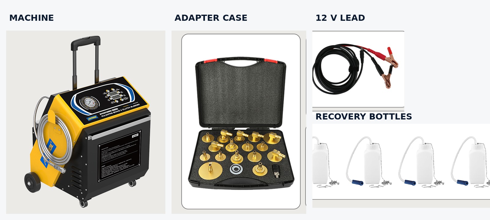
Inspect the enclosure, handle, wheels, tank, filler, cap, level view, drain, hose, coupler, seals, gauge lens and pointer, cable, clamps and recovery containers. Reject cracks, swelling, brittleness, cuts, corrosion, contamination, loose components, damaged insulation or unreadable indication.
Confirm that the selected reservoir adapter is clean and its exact seal is pliable, correctly seated and undamaged. Confirm that each recovery hose fits its bottle and planned bleeder connection without being stretched or kinked.
Completion check: Every required part is present, clean, intact and assigned to the correct clean-fluid, pressure, electrical or recovery role.
Phase B: fill and prime the AST618 supply path
Step 6: Fill the clean new-fluid storage tank
Place AST618 upright on a stable level surface. Lock or position it so hose tension cannot roll or tip it. Clean the filler area before opening it, then add only new brake fluid that matches the exact vehicle specification.
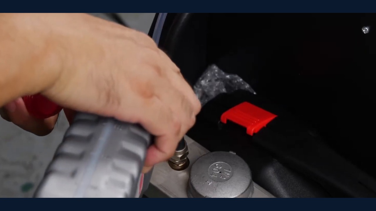
The tank’s rated size is not permission to fill to an arbitrary amount. Calculate the supply from the vehicle procedure, expected circuit work, off-vehicle priming and a visible reserve. Never mix specifications or return recovered fluid, priming discharge or uncertain remaining fluid to the clean supply.
Close the filler as directed and remove spilled fluid from the machine immediately with material compatible with the fluid and equipment finish. Do not place solvent-, fuel- or oil-soaked cloths on the machine.
Stop: If the fluid identity, cleanliness or available quantity is uncertain, close the tank and resolve it before powering the machine.
Completion check: The tank contains sufficient clean exact-specification new fluid, the filler is closed and clean, and the level remains visible from the operating position.
Step 7: Arrange the output, priming capture and power lead
Keep the reservoir adapter off the vehicle. Attach it to the output quick coupler only if that is the secure priming arrangement for the delivered revision. Direct the outlet into a stable compatible collector that cannot tip or spray fluid onto a person, paint, tires, brakes or electrical parts.
Route the output hose with enough slack for priming and later reservoir connection. Avoid loops that trap tension, tight bends, sharp edges, heat, moving parts and foot traffic. Keep the coupling and adapter sealing faces clean.
With the power switch off, make the verified 12 V DC connection using correct polarity. Keep the cable separate from fluid capture and ensure the machine, collector and lead cannot move when delivery begins.
Do not open a vehicle bleeder or connect the adapter to the reservoir at this stage.
Completion check: The clean output is secured over compatible priming capture, the machine is stable, the 12 V lead is correctly connected and no vehicle hydraulic boundary is open.
Step 8: Prime the output away from the vehicle
Switch AST618 on and press Start/Pause while holding the priming outlet securely in the collector. Watch the tank level, output hose, coupler and discharge. Continue until fresh fluid exits as a stable stream with no visible air interruption.
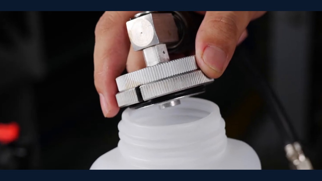
Prime on first use and after changing fluid type, draining the machine or opening the clean supply path. Prime again if the tank inlet may have been exposed.
Do not treat a short timed run as proof that all air has left the path. If bubbles continue, stop and inspect the supply level, tank closure, hose, coupler and fluid path rather than increasing pressure blindly.
Press Stop/Relief while the outlet remains securely directed into capture. Treat all priming discharge as removed shop fluid; never return it to the tank or vehicle.
Stop: Press Stop/Relief for no flow, low tank reserve, aerated discharge, leakage, machine movement or abnormal gauge behavior. Isolate the cause before restarting.
Completion check: Stable air-free new fluid reached the controlled collector and Stop/Relief was pressed without a leak, exposed supply pickup or abnormal machine response.
Step 9: Wait and prove stable zero before reconfiguration
Keep the outlet, adapter and all pressure-side connections assembled after pressing Stop/Relief. Wait at least 10 seconds while watching the analogue gauge. Do not use motor silence, an inactive display or elapsed time alone as proof that pressure is gone.
Confirm that the gauge reaches zero and remains there. If it does not, press Stop/Relief again, wait and observe. Keep the boundary intact until zero is stable. Never loosen a coupling, cap or fitting to vent pressure.
If repeated relief does not produce stable zero, switch off according to the delivered instructions, leave the pressure side assembled and obtain qualified service support. Do not force the quick coupler apart.
Only after stable zero is proved may you remove the priming collector arrangement and carry the protected clean adapter/output to the vehicle.
Completion check: At least 10 seconds have passed after the final relief command, the gauge remains stably at zero and no pressure-side connection was moved while pressure was present or uncertain.
Phase C: seal the reservoir, stage recovery and service each point
Step 10: Prepare the reservoir
Protect nearby paint and clean loose dirt from around the reservoir cap without allowing water, solvent, lint or debris inside. Inspect the cap, diaphragm, neck, threads or locking features and sealing surface.
Reconfirm the exact fluid, vehicle state, pressure-assisted method and starting fluid level. Set the level only as the vehicle procedure requires. Do not fill the reservoir to the brim or near overflow; the correct level and required expansion or diaphragm space belong to the exact vehicle design.
If existing fluid is unknown, visibly contaminated or inconsistent with the specified fluid, stop. Use the vehicle manufacturer’s contamination or repair procedure instead of pushing new fluid through an uncertain system.
Completion check: The reservoir opening and seal surface are clean and undamaged, and the exact fluid, level, system state and pressure method are reconfirmed.
Step 11: Install the exact adapter and connect the primed output
Compare the reservoir geometry and attachment method with the selected adapter. A make list, case position or approximate diameter does not prove fit. The profile, thread, bayonet, cone, retainer and seal must match the physical reservoir.
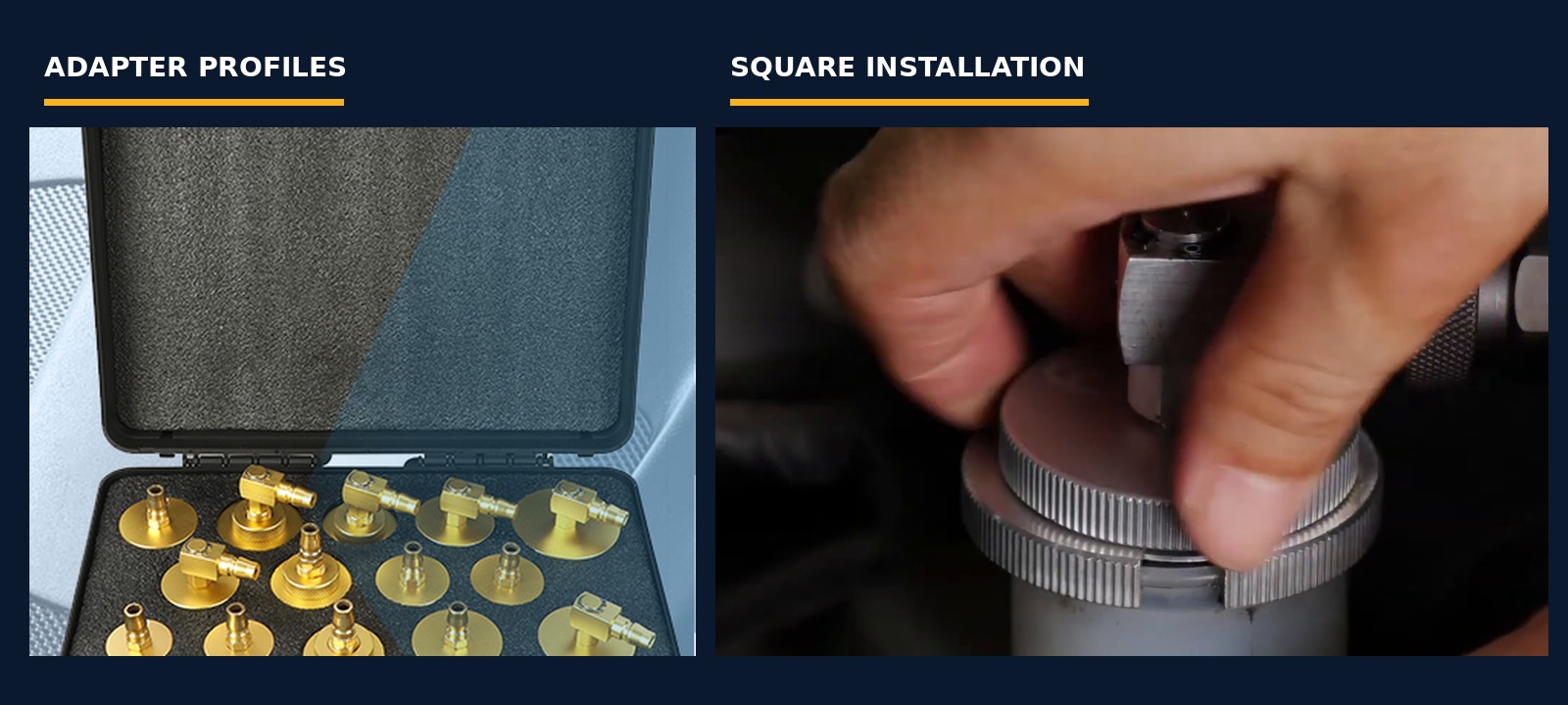
Install the clean adapter squarely by its intended method. Never force, cross-thread, shim or improvise a near fit. Do not use machine pressure to pull it into position. With AST618 stopped and stably at zero, connect the primed output coupling fully.
Route the output so it cannot twist, lift or side-load the adapter as the vehicle is approached. If the vehicle must be raised after connection, confirm that no hose or cable can snag, stretch or contact a moving lift part. Every vehicle bleeder remains closed.
Completion check: The exact adapter sits squarely with an intact seal, the primed coupling is fully seated, the hose is untensioned and every service point remains closed.
Step 12: Stage the required recovery paths
Use the vehicle-defined service-point order to plan access. Fit a clear compatible hose to each recovery bottle required by the procedure. Keep every bottle upright, visible and stable, away from wheels, suspension, brakes, exhaust and lift parts.
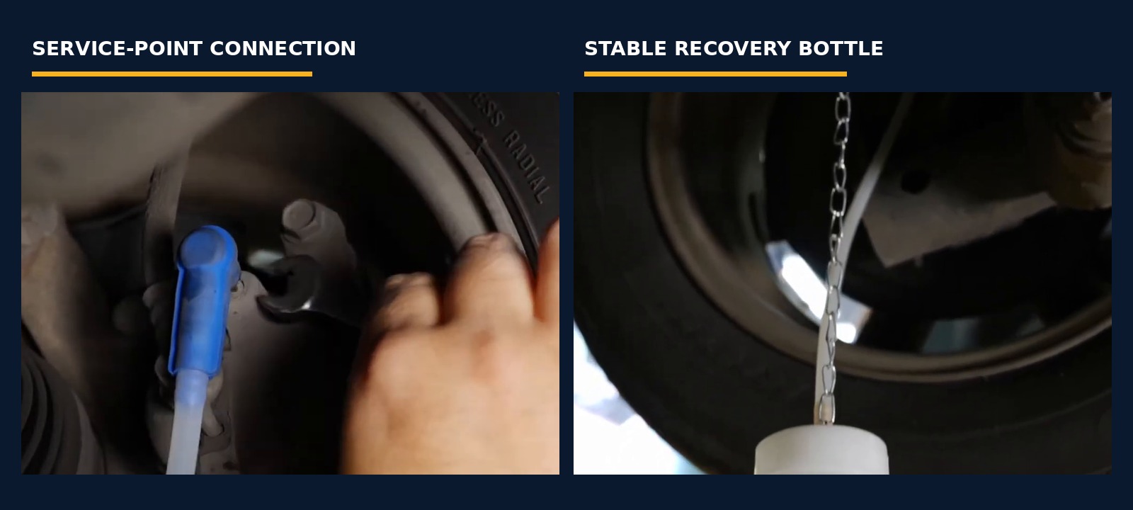
Clean each bleeder area and inspect for corrosion, rounding, cracks, blockage or previous damage. Use the exact-size tool. Fit the clear hose securely without applying side load. Leave every bleeder closed until its turn in the exact vehicle sequence.
If the vehicle procedure explicitly requires a supported multi-point method, follow its complete connection, observation, opening and closure rules. Otherwise, use one active point at a time. Do not infer simultaneous permission from the number of bottles or a promotional image.
Completion check: Every required recovery bottle is stable and correctly routed, every hose and bleeder is inspectable, and all bleeders remain closed.
Step 13: Build only the vehicle-permitted condition and prove the boundary
Review the exact vehicle pressure limit immediately before starting. Capability ranges, factory conditions and filmed display values describe the machine; they do not authorize a setting for this reservoir, adapter or hydraulic system.
Set the required ignition, engine, booster and diagnostic state from the exact vehicle procedure. Press Start/Pause while continuously watching the gauge, tank reserve, output hose, coupling, adapter and reservoir. Use Pressure controls only within the applicable lower equipment/vehicle boundary.
Do not change Pulse simply to speed the job. If the delivered exact instructions and applicable vehicle method do not give a reason to change it, retain the verified condition and judge the hydraulic result by the vehicle procedure. The Time control can divide work into observation intervals; a timer stop does not prove a circuit is finished.
With every bleeder still closed, prove that the entire machine-to-reservoir boundary is dry, stationary and stable. An unexplained rise, collapse, drift, hose expansion, hiss, adapter movement, seepage or abnormal sound is a stop condition.
Stop: Close any unexpectedly open point, press Stop/Relief, wait and prove stable zero before inspecting a leak, moving adapter or unstable hose.
Completion check: The machine-to-reservoir path remains dry, stationary and stable at conditions permitted by the exact vehicle and delivered AST618 instructions, with every bleeder still closed.
Step 14: Service and close each vehicle-prescribed point
Go to the first point named by the exact vehicle procedure. Confirm its recovery hose and bottle are secure. Open the bleeder only by the prescribed amount and watch the active discharge, tank reserve, gauge, adapter, output hose and all staged recovery paths.
Do not leave AST618 unattended because it can run for a set interval. Keep enough new fluid visible in the tank that the supply cannot ingest air before the next observation. The low-fluid alarm and automatic stop are secondary protections, not a substitute for watching the reserve.
Use the exact vehicle endpoint. Fluid color, a nominal volume, no visible bubbles, elapsed time or timer expiry can support observation but cannot replace the prescribed endpoint. Bubbles can originate in the machine path, reservoir seal, vehicle circuit or around bleeder threads; persistent unexplained bubbles require isolation, not a declaration that the brakes are finished.
When the active point reaches its prescribed endpoint, close the bleeder by the exact method before moving to another point. Inspect the closed bleeder and recovery path for leakage. Only then move to the next vehicle-prescribed point.
Stop: Close the active bleeder first for low supply, no flow, persistent bubbles, pressure change, leakage, adapter movement, hose damage or an uncertain endpoint. Then press Stop/Relief.
Completion check: Each required point reached its exact vehicle-defined endpoint, was closed correctly and remained dry before the next point began.
Step 15: Close the final bleeder before Stop/Relief
At the final required service point, continue only until the exact vehicle endpoint is met. Close the bleeder by its specified method while AST618 is still maintaining the controlled reservoir boundary. Verify that its clear hose no longer shows active discharge and that the bleeder remains dry.
Do not press Stop/Relief while a bleeder is open. That order can disturb the controlled path and can allow an uncertain hydraulic result. Do not disconnect the recovery hose as a substitute for closing the bleeder.
After the final bleeder is closed, visually confirm that every serviced bleeder is closed and that the recovery bottles are stable. Then press Stop/Relief once while observing the gauge and reservoir adapter.
Completion check: The final endpoint is met, all serviced bleeders are closed and dry, and Stop/Relief was pressed only after the final bleeder closed.
Phase D: prove zero, drain the machine and release only a verified vehicle
Step 16: Prove stable zero before disconnecting and drain by fluid role
Leave the adapter, output hose and quick coupler assembled after Stop/Relief. Wait at least 10 seconds and watch the gauge. If it is not at zero, press Stop/Relief again, wait and observe. Do not touch the pressure boundary until the pointer reaches zero and remains there.
Once stable zero is proved, switch and disconnect power by the delivered procedure. Place paint protection and compatible capture beneath the adapter. Disconnect the output coupling without twisting the reservoir, then remove the adapter squarely. Immediately protect the clean coupling and restore the reservoir opening from contamination.
Separate fluids by role. Wheel-side bottle contents are used vehicle fluid and must never return to the vehicle or machine tank. Remaining machine-tank fluid has been opened and handled; manage it under the fluid label, shop policy and local rules. Do not return uncertain remaining fluid to a sealed new container.
With the machine completely disconnected from the vehicle and the outlet secured into labelled compatible capture, drain the storage tank by the delivered method. If the instructions call for controlled Start cycles through the output, keep the outlet secured and the tank observed.
Use the drain port only in the specified unpressurized condition. Never open the enclosure or loosen an internal fitting to empty the tank.
Stop: If the gauge will not remain at zero, a coupling resists release, the drain path leaks or the fluid destination is uncertain, keep the system isolated and obtain qualified support.
Completion check: Stable zero was proved before every pressure-side disconnection, the vehicle adapter was removed cleanly and all remaining fluids were captured, separated and assigned to the correct handling route.
Step 17: Restore the vehicle and complete the no-road gate
Set the reservoir to the exact specified level and reinstall its correct cap, diaphragm and any surrounding parts. Remove protection without transferring fluid to paint, tires, pads, rotors, electrical connectors or the work area. Clean any spill immediately by the fluid and vehicle instructions.
Inspect the reservoir, adapter area, every serviced bleeder, hose, line and disturbed component for leakage. Tighten bleeders only by the exact specification; do not add force simply because a spot is wet. A damaged bleeder or sealing seat needs repair.
Establish the exact ignition, engine, booster and diagnostic state for the final tests. Perform the prescribed pedal, warning-lamp, fault-code, actuator and stationary hydraulic checks. A firm pedal on one application, clear fluid or no visible bubbles alone is not proof that the system is safe.
Do not move the vehicle with leakage, a falling or uncertain level, or an abnormal or sinking pedal. An active brake warning, unresolved diagnostic fault, incomplete electronic routine or any other uncertainty also blocks movement. Diagnose and correct the condition, then repeat the required acceptance checks.
Record vehicle identity, fluid used, work performed, service-point sequence, observed abnormalities, corrective actions and final results. Store the clean dry machine and accessories only after all residues are removed and every hose, seal, cable and bottle is inspected.
Completion check: Exact level and cap, leak inspection, pedal, warning, diagnostic and stationary acceptance checks all pass, the work is recorded and no unresolved condition remains before vehicle movement.
Interrupted-cycle recovery
Use the same isolation order for any abnormal event. Close the active bleeder, press Stop/Relief and wait at least 10 seconds. Repeat relief if needed and prove stable zero before touching the pressure side.
| Event | Immediate action | Before restart |
|---|---|---|
| Tank reserve becomes low or inlet may have been exposed | Close the active bleeder and press Stop/Relief | Prove zero, determine whether air entered, refill with exact fluid, re-prime away from the vehicle when required, then repeat the affected vehicle step |
| Adapter or output connection leaks | Close, stop and keep the boundary assembled until zero | Clean, inspect and replace the exact seal or adapter as needed; prove a dry closed-boundary test before reopening a bleeder |
| No flow at an active point | Close and isolate without raising pressure by guess | Check supply, hose routing, couplers, bleeder condition and exact vehicle/electronic state after zero; diagnose an obstruction by the vehicle procedure |
| Bubbles persist | Close and isolate | Check machine priming, supply level, reservoir seal, hose seating and thread-side air; repeat the exact procedure until its endpoint is genuinely met |
| Pressure rises, collapses or drifts | Close and press Stop/Relief | After zero, inspect for a closed path, restriction, leak, moving adapter, hose damage or incorrect setting; never chase the gauge blindly |
| Timer expires before endpoint | Close the point if observation cannot continue | Confirm supply and boundary, then resume only under the exact vehicle procedure; do not declare completion from the timer |
| Power is interrupted | Close the active bleeder immediately | Prove or safely obtain zero, inspect the electrical and fluid paths, re-prime if air entry is possible and restart the required step |
| Gauge will not reach or hold zero | Keep all pressure connections assembled | Repeat Stop/Relief only as directed; isolate power and obtain qualified service if stable zero cannot be proved |
Troubleshooting after isolation
Troubleshoot only after the active bleeder is closed and the gauge remains at zero. Never crack a fitting to test for pressure or use a higher pressure to force a result.
AST618 runs but no fluid reaches the bleeder
First separate a machine-supply problem from a vehicle-path problem. Confirm correct new fluid remains visible, the output was primed, the quick coupler is fully seated, no hose is kinked and the reservoir adapter boundary is intact. Then check that you are at the correct vehicle point, the bleeder is actually open by the prescribed amount and the required electronic or hydraulic state is active.
A blocked bleeder, collapsed hose, closed vehicle valve or unsupported ABS state is not permission to increase Pressure. Close, isolate and use the exact diagnostic path.
The reservoir adapter hisses or pressure falls
Close the active bleeder and press Stop/Relief. After stable zero, inspect the reservoir neck, exact adapter geometry, seal position, threads or locking features and hose side-load. Clean fluid from the area before judging the leak.
Do not tighten past the adapter’s intended stop, stack improvised seals or lower pressure merely to tolerate an unproved fit. Rebuild a correct dry boundary and test it with all bleeders closed at a vehicle-permitted condition.
Bubbles keep appearing in the clear hose
Persistent bubbles can come from incomplete machine priming, low tank reserve, a leaking reservoir boundary, a loose recovery hose or air entering around bleeder threads. They may also reflect air still present in the vehicle circuit.
Close and isolate before checking. Correct the source, re-prime when necessary and repeat the exact vehicle step. Do not call the job complete because fluid color changed or because bubbles temporarily disappeared.
The pedal remains soft after bleeding
Keep the vehicle stationary. Recheck exact fluid level, all bleeders and disturbed connections for leaks. Confirm the required service order, master-cylinder preparation and ABS or brake-by-wire routine were completed. A mechanical fault, internal master-cylinder issue, flexible-hose expansion, caliper condition or trapped circuit air may require diagnosis beyond fluid exchange.
Do not repeat a generic flush indefinitely or use a road test to discover whether the pedal is acceptable.
Stop/Relief does not produce stable zero
Leave the adapter, hose and coupler connected. Press Stop/Relief again only as the delivered instructions allow, wait at least 10 seconds and observe. If the pointer stays above zero, returns after falling or behaves abnormally, isolate power without opening the pressure path and obtain qualified machine service.
AST618 care after the job
Drain remaining machine fluid by the delivered external outlet or drain-port procedure only after the vehicle is disconnected and pressure is stably zero. Capture it in a labelled compatible container. Empty wheel-side recovery bottles into the designated used-fluid container and never combine their contents with clean supply.
Wipe residue promptly. Inspect the tank, filler, output hose, coupler, adapters, seals, recovery hoses, bottles, power lead and clamps. Keep clean-fluid components capped and separated from used-fluid equipment. Store the unit upright in a clean, dry location protected from heat, impact and contamination.
Do not open the enclosure, alter calibration, substitute electrical protection, flush the machine with an unlisted chemical or attempt an internal pressure repair. Remove damaged or abnormally operating equipment from service.
Frequently asked questions
What pressure should I set on the AST618?
Use a value permitted by the exact current vehicle, reservoir and adapter procedure and within the delivered AST618 limits. Do not copy a product range, factory condition, video display or another vehicle’s setting. If the vehicle provides no pressure-assisted limit, obtain the correct service information before proceeding.
Which Pulse setting should I use?
There is no universal Pulse value. Use the delivered exact-model instruction together with the applicable vehicle method. Do not increase Pulse merely to shorten the job, and stop if it produces unstable pressure, hose movement, leakage or an abnormal result.
Does the one-minute Time setting mean the fluid exchange is complete?
No. Time is an operating interval. The vehicle procedure defines completion through its required fluid, sequence, observation, volume, diagnostic and acceptance conditions. If the timer stops before that endpoint, isolate or resume under controlled observation; never declare the circuit finished from elapsed time alone.
Can AST618 bleed all four wheels simultaneously?
Four recovery bottles do not establish universal simultaneous permission. Use one active point by default and follow the exact vehicle order. Open more than one point only when the current vehicle procedure explicitly supports the complete multi-point method and every path can be observed and closed correctly.
Do I need to prime AST618 before every job?
Prime before first use, after changing fluid type and after draining or opening the clean-fluid path. Prime after a low-supply event that may have admitted air and whenever output is not demonstrably stable and air-free. A short timed run is not a substitute for observing the output.
Can I fill the vehicle reservoir to the top before installing the adapter?
Set the level only as the exact vehicle procedure specifies. Do not fill to the brim or near overflow. The reservoir, cap and diaphragm may need defined space, and spilled brake fluid can damage paint.
What should I do if the low-fluid alarm stops the machine?
Close the active bleeder, press Stop/Relief and prove stable zero. Determine whether the supply path admitted air. Refill only with the exact new fluid, re-prime away from the vehicle when air entry is possible, and repeat the affected vehicle step as required. Do not assume the alarm prevented all air entry.
Can I reuse fluid left in the recovery bottles or priming container?
No. Never return wheel-side recovered fluid or priming discharge to the vehicle or machine tank. Handle it as used fluid. Treat opened remaining tank fluid according to its label, shop policy and local rules; do not pour uncertain fluid back into a sealed new container.
Is bubble-free fluid enough to release the vehicle?
No. Complete the exact level and cap restoration, leak inspection, pedal checks, warning and fault checks, any required diagnostic routine and all stationary acceptance tests. Any abnormal or uncertain result keeps the vehicle off the road.
Final AST618 checklist
Before starting:
- exact vehicle procedure permits pressure-assisted service;
- correct new unopened fluid and sufficient reserve are ready;
- exact adapter and seal fit the physical reservoir;
- AST618 identity, controls, gauge and 12 V DC lead are verified;
- machine, tank, hoses, couplers, bottles and cables are clean and intact;
- vehicle support, PPE, paint protection, capture and waste route are ready.
Before connecting the reservoir:
- output was primed away from the vehicle to stable air-free discharge;
- Stop/Relief was pressed;
- at least 10 seconds elapsed; and
- the gauge reached and held zero before reconfiguration.
During vehicle service:
- the adapter boundary is dry, stationary and within exact vehicle limits;
- every recovery path was staged with its bleeder initially closed;
- one vehicle-prescribed point is active by default;
- tank reserve, gauge, adapter, hoses and active discharge stay observed;
- Pressure, Pulse and Time are not used as universal settings or endpoints;
- every completed bleeder is closed and dry before moving on; and
- any abnormal event triggers close, Stop/Relief, wait and stable-zero isolation.
Before vehicle movement:
- the final bleeder closed before Stop/Relief;
- at least 10 seconds and stable zero were proved before disconnecting;
- exact reservoir level, diaphragm and cap are restored;
- no reservoir, bleeder, line or disturbed connection leaks;
- required pedal, warning, diagnostic and stationary checks pass;
- all fluid is captured, separated and handled correctly; and
- the vehicle remains stationary if any condition is abnormal or uncertain.











Comments 0
Questions, fixes, and real-world diagnostic notes from readers.
Be the first to share a diagnostic result or ask a follow-up question.