
How to Use the AUTOOL AST603 Brake Fluid Bleeder

The AUTOOL AST603 brake fluid bleeder supplies pulsating pressure to an eligible vehicle’s brake-fluid reservoir so a qualified operator can bleed or exchange fluid at the prescribed wheel points. Confirm the exact vehicle procedure and fluid first, prime the AST603 into a catch container before connecting it to the vehicle, and keep every pressure-side connection assembled until the gauge is stably at zero.
The vehicle manufacturer—not the AST603 pressure range, a product picture or a generic wheel-order chart—controls the fluid specification, pressure, bleed sequence, electronic-system state, bleeder method and final brake checks. Stop before starting if any of those decisions are missing.
Last reviewed: August 29, 2026.
In this guide
- The AST603 workflow at a glance
- What the AST603 does—and what it cannot decide
- Before you start
- Know the controls, hoses and delivered parts
- Phase A: qualify and prepare
- Phase B: prime an air-free filling path
- Phase C: seal the reservoir and bleed the prescribed points
- If the normal cycle is interrupted
- Phase D: return the vehicle and tool to a safe state
- AST603 troubleshooting and stop rules
- Frequently asked questions
- The job ends with a verified vehicle and a zero-pressure tool
The AST603 workflow at a glance
One controlled job has four phases:
- Qualify and prepare. Confirm that pressure bleeding is permitted for the exact vehicle and repair state. Obtain the correct new fluid, reservoir adapter, tools, procedure and safe working conditions; match the delivered AST603 voltage to a grounded supply.
- Prime away from the vehicle. Put both supply hoses into the new-fluid container, set the pressure control to its lowest position and run the filling path into a catch container until the discharge is bubble-free. Stop, isolate power and wait for stable zero before changing the connection.
- Seal and bleed under vehicle control. Fit the exact reservoir adapter without force, prove the entire pressure boundary leak-free, then service only the prescribed points in the prescribed order while watching the clean-fluid reserve, gauge, adapter, hoses and used-fluid bottle.
- Close, zero and verify. Close the final bleeder before stopping the machine. Reach stable zero before disconnecting the reservoir, then restore level and cap condition, inspect for leaks and complete every required pedal, warning and diagnostic check before the vehicle moves.
Stop if you find a leak, a moving adapter, a damaged hose, persistent pressure instability, low or lost clean-fluid supply, an air-entry event, an electrical abnormality or an unsafe brake result. Correct the cause under the exact procedure or obtain qualified service.
What the AST603 does—and what it cannot decide
The AST603 draws new brake fluid from a separate container and sends it through its filling hose to a sealed reservoir adapter. Pulsating pressure supports one-person fluid delivery when the entire setup remains visible and stable. At each prescribed bleeder, the operator routes removed fluid through a clear hose into a used-fluid bottle.
The machine does not decide whether a particular vehicle can use this method. It does not select a brake-fluid chemistry, adapter, pressure, wheel order, bleeder torque, ABS routine or exchange endpoint. Its automatic low-fluid or pressure behavior is backup protection, not permission to leave the machine unattended.
Do not treat the AST603’s pressure capability as a setting. Use only a pressure permitted by the current vehicle procedure and within the verified limits of the delivered machine and adapter. If the vehicle requirement and the machine’s safe operating behavior cannot both be satisfied, do not connect the tool.
Brake bleeding is also not a complete diagnosis. Fresh fluid or a bubble-free clear hose does not explain every soft pedal, prove every hydraulic component sound or authorize road use. A pre-existing leak, unexplained low level, soft or sinking pedal, brake warning or unknown repair state must be diagnosed before routine exchange.
Before you start
Get the vehicle decisions in writing
Have the current service procedure open at the work area. Record these items before removing the reservoir cap:
- exact brake or clutch hydraulic system and whether pressure bleeding is permitted;
- required brake-fluid specification and any compatibility restrictions;
- maximum permitted filling pressure and the prescribed operating method;
- reservoir adapter or cap profile;
- wheel, caliper and bleeder sequence, including multiple bleeders on one caliper;
- ignition, engine, booster, ABS, EPB or scan-tool state;
- bleeder opening method, final torque and protective-cap requirements;
- required fluid quantity, flow condition, diagnostic cycle or other endpoint;
- final reservoir level, stationary pedal, warning/fault and functional-test criteria.
Do not substitute a generic farthest-wheel-first rule. Some vehicles use a different sequence, more than one bleeder per caliper or a diagnostic activation that changes the hydraulic state. The exact vehicle procedure must stay in control from the first connection through the final check.
Use only the exact new brake fluid
Use a new, unopened container that matches the vehicle specification and is compatible with the tool’s hoses and seals. Keep it closed until the setup is ready. Follow its label and safety data sheet for moisture exposure, gloves, spill response, storage and disposal.
Do not mix glycol and silicone families, mineral hydraulic fluid, incompatible DOT classes, old and new fluid, or fluid from an unidentified container. Never return priming fluid or removed fluid to the clean supply. If the existing fluid is wrong, contaminated or unknown, stop and obtain the vehicle manufacturer’s remediation procedure; routine exchange is not enough.
Prepare a controlled work area
Place the vehicle on the exact prescribed support and restraint system, with safe access to every required bleeder. Control the key and ignition state. Keep the AST603 on a dry, flat, stable surface close enough that its filling hose reaches without tangling, twisting, stretching or touching a hot or moving part.
Wear splash goggles and gloves selected for the brake fluid. Protect painted surfaces and keep compatible spill-control materials ready. Provide a correctly sized bleeder wrench, a snug transparent hose, a stable compatible collection bottle and labelled waste containers. Route power and fluid hoses so nobody can trip over or pull them.
The operator must be able to observe the machine, new-fluid supply, reservoir adapter and active wheel point. Use a second observer if the setup hides any of them.
Know the controls, hoses and delivered parts
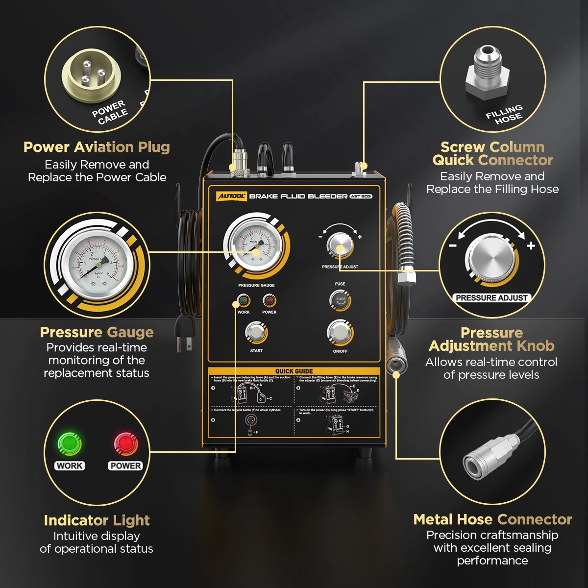
Identify components by their physical name rather than by a letter from an illustration. Exact AST603 diagrams use different letter assignments.
| Component | What it does | What to verify |
|---|---|---|
| Pressure gauge | Shows machine-side pressure | Face is legible, pointer is stable and it returns to zero |
| Pressure-regulation knob | Changes the requested pressure | Turns normally and begins at its lowest position |
| Start control | Starts priming or pressure delivery | Button and indicator behavior match the delivered instructions |
| Mains switch and power lead | Energize and isolate the unit | Delivered voltage, plug, protective earth and cord are intact |
| Suction hose | Draws new fluid from the supply | Clean, undamaged and routed to the bottom of the new-fluid container |
| Pressure-balance hose | Returns/balances the new-fluid supply path | Clean, undamaged and routed to the bottom of the same container |
| Filling hose and quick coupling | Carry fluid to the priming or reservoir adapter | No cut, swelling, kink, loose fitting or contamination |
| Reservoir adapter and seal | Close the vehicle reservoir pressure boundary | Exact profile, clean sealing face and undamaged gasket; no near-fit substitution |
| Used-fluid bottle and clear hose | Capture fluid at a bleeder | Stable, compatible, correctly routed and not configured as an unintended pressure vessel |
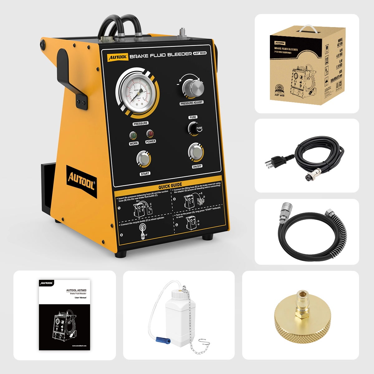
The current standard package shows one brass reservoir adapter. Additional adapter sets are optional. A brass cap that looks close is not proof of fit for a vehicle.
Phase A: qualify and prepare
Step 1: Approve the exact vehicle procedure
Identify the vehicle, brake system and reason for service. Confirm that the hydraulic system is not already blocked by an unresolved leak, wrong fluid, unexplained low level, unsafe pedal or warning. If a master cylinder, ABS unit, caliper, line or hose was replaced—or the circuit ran dry—obtain the complete filling, activation and recovery procedure for that repair.
Write down the fluid, adapter, pressure limit, wheel order, electronic states, bleeder method, endpoint and final checks. Do not begin an ABS, EPB, brake-by-wire, regenerative-braking or electronic-booster procedure from a feature name or a generic scan-tool prompt.
Completion check: The exact procedure expressly supports the planned pressure-bleeding job, every vehicle-dependent decision is available, and the initial hydraulic condition is safe enough to begin.
Stop: Do not open the reservoir for routine exchange while a leak, wrong/unknown fluid, incomplete repair procedure, unsafe pedal or unresolved warning remains.
Step 2: Match the delivered AST603 and mains supply
Confirm AST603 on the actual machine. Treat the 110 V and 220 V versions as separate equipment; do not assume a selector or automatic voltage change. Match the nameplate, frequency, plug and protective-ground connection to the available supply. Keep hands, plug, switch and enclosure dry.
Use the AUTOOL manual download center to locate AST603, then compare the manual’s control layout and warnings with the unit in front of you. If the rating plate, panel, hose arrangement, electrical labels or delivered instructions do not match, stop and identify the correct revision before use.
Completion check: The model and delivered voltage are confirmed, the grounded supply matches, and the applicable AST603 instructions agree with the physical controls and connections.
Step 3: Prepare the work area, fluid and tools
Support and restrain the vehicle exactly as required. Clean and light the work area, establish ventilation, protect paint, put on splash goggles and compatible gloves, and position spill and waste controls. Set out the exact wrench, transparent hose and catch bottle for each bleeder.
Obtain enough unopened vehicle-specification brake fluid for the prescribed service plus the fluid needed to prime the AST603 while keeping both supply hoses submerged. No universal quantity fits every vehicle or repair state.
Place the machine so the filling hose reaches every required service point without twisting or tension. Do not energize it yet.
Completion check: The vehicle is safely supported, every required point is accessible, the operator can see all risk points, and sufficient correct new fluid, PPE, tools and waste capacity are ready.
Step 4: Inspect the AST603 and check the kit
Inspect the enclosure, handle, labels, pressure gauge, pressure knob, Start control, indicators, mains switch, cord/plug/earth, fluid holder, suction and balance hoses, filling hose, quick coupling, adapter/seal and used-fluid bottle/hose.
Keep the machine out of service for a crack, cut, swelling, corrosion, loose or leaking fitting, distorted container, damaged electrical part, unreadable or unstable gauge, sticking control, contaminated hose, missing seal or improvised adapter. Do not open the enclosure, substitute an unspecified fuse or repair a pressure/electrical fault yourself.
Completion check: Every required component is present, clean, intact and identified, and no defect or mismatch remains to be worked around.
Phase B: prime an air-free filling path
Step 5: Position the new-fluid supply
Keep power disconnected. Put the new unopened brake-fluid container securely in the holder. Route both the suction hose and pressure-balance hose to the bottom of the container without crossing, kinking or pulling them. Keep the fluid clean; do not place a dirty hose on a bench and then return it to the supply.
No universal fill line or low-level number is established for this setup. The practical requirement is enough clean fluid to prime and complete the prescribed vehicle procedure while both hose ends remain submerged. Keep the container and hose ends continuously visible.
Completion check: The correct fluid container is stable, both clean supply hoses reach its bottom, the reserve is sufficient and the full route remains visible.
Step 6: Prime the filling hose away from the vehicle
Turn the pressure-regulation knob fully toward its lowest position. Connect the reservoir adapter to the filling-hose quick coupling for the priming setup, but do not install it on the vehicle. Place and hold the adapter outlet inside a stable compatible capture container so discharged fluid cannot spray.
Connect the verified mains supply and switch the AST603 on. Operate the Start control while watching the adapter outlet, supply hoses, container level, filling hose, connections and gauge. Continue only until a steady discharge without bubbles proves that the internal path and filling hose are full of fluid.
Do not use a fixed number of seconds. Time alone cannot prove that the filling path is full; continue only to a steady bubble-free discharge. Stop immediately for no flow, persistent air after the setup has been rechecked, a falling or empty supply, a leak, abnormal noise, an unstable gauge, hose movement, fluid near electrical parts, heat, odor or smoke.
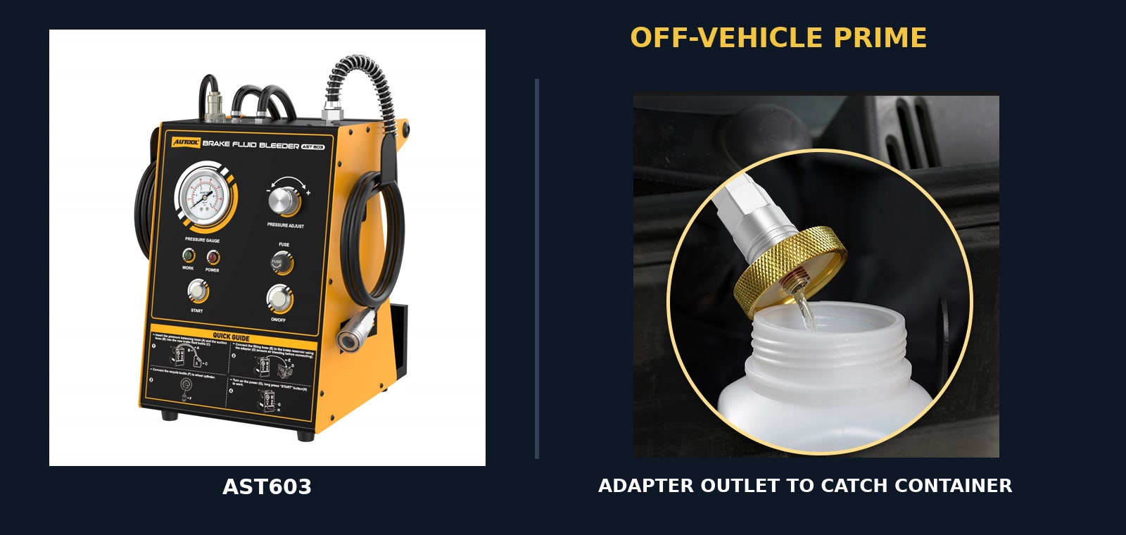
Completion check: Fluid leaves the adapter outlet in a steady bubble-free stream, the supply remains safely above both hose ends, and every machine-side connection stays dry and stable.
Step 7: Stop priming and prove stable zero
Release the Start control, switch the machine off and unplug it with dry hands. Keep the priming assembly intact while the gauge returns to zero. Wait until the pointer remains at zero; do not treat a pointer that only briefly touches zero, or a quiet pump, as proof of depressurization.
Only after stable zero may you release the priming adapter from the filling-hose coupling. Capture drips without letting the hose end touch a dirty surface. If the gauge will not reach or hold zero, leave the pressure-side assembly connected, keep people clear and obtain qualified service.
Completion check: Electrical power is isolated, the gauge is stably at zero and the primed filling hose remains clean and full without a live connection being loosened.
Phase C: seal the reservoir and bleed the prescribed points
Step 8: Prepare the reservoir and install the exact adapter
Protect nearby paint. Clean loose dirt from around the reservoir and cap without allowing water, fibers, cleaner or debris inside. Confirm the fluid specification once more before opening the reservoir. Inspect the cap, diaphragm, neck, threads or bayonet features and sealing surface.
Compare the exact vehicle reservoir with the approved adapter profile and gasket. Align the adapter squarely and install it by the prescribed method. Never force a near fit, cross-thread it, use pressure to pull it into place or add an improvised seal.
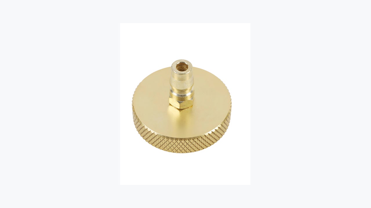
Completion check: The reservoir area is clean, the correct adapter sits squarely on the intended sealing features, and no force, distortion, debris or damaged seal is present.
Step 9: Couple the filling hose and prove the pressure boundary
Keep every vehicle bleeder closed. Connect the primed filling-hose quick coupling fully to the reservoir adapter and verify that its locking mechanism is engaged. Route the filling hose without tension, twisting, heat, moving-part contact or a path that can pull the adapter.
Set the pressure knob at its lowest position, connect power and switch on. Press and hold Start while increasing the knob slowly, stopping the increase as soon as the vehicle-prescribed condition is reached. Release Start only as the delivered AST603 instructions permit normal operation at that stable condition. Watch the gauge, new-fluid reserve, supply hoses, filling hose, quick coupling, adapter, reservoir and surrounding paint.
Do not raise pressure merely to copy an image or cross a machine operating threshold. If the vehicle limit and the delivered unit’s normal operating behavior cannot both be satisfied, the setup is not compatible. Stop for seepage, pressure loss or drift, adapter movement, reservoir distortion, hose expansion, abnormal pump behavior or fluid loss. Release Start and return to stable zero before touching any connection.
Completion check: The exact vehicle-approved condition is stable with all bleeders closed, and the entire machine-to-reservoir pressure boundary remains stationary, dry and leak-free.
Step 10: Prepare the first prescribed bleeder and catch path
Go to the first point named by the vehicle procedure. Identify the exact bleeder, clean around it and inspect it for damage or corrosion. Use the correct-size wrench; do not force a seized or rounded screw. Fit a snug transparent hose and route it into a stable compatible used-fluid bottle where flow and bubbles can be observed without a spill.
Keep the hose away from brakes or suspension parts that may move, and keep the bottle from tipping or being pulled. Do not seal an unqualified bottle so that it becomes pressurized.
Completion check: The correct bleeder is clean and serviceable, the wrench fits, and the transparent hose and bottle are secure, visible and spill-controlled.
Step 11: Bleed and close every required point in order
Open the bleeder only by the amount and method specified for that caliper or component. Observe the clear hose while continuing to watch—or having a second operator watch—the AST603 gauge, new-fluid reserve, both supply hoses, reservoir adapter, filling hose and surrounding leaks.
Maintain enough new fluid to keep both supply hoses submerged. Do not rely on automatic shutdown. If the supply approaches an uncertain level, close the active bleeder, stop output and return safely to stable zero before correcting the setup. If air enters the machine or vehicle, stop the normal cycle and follow the exact recovery or re-bleed procedure before continuing.
Use the vehicle-prescribed endpoint. A stable bubble-free stream may be one required observation, but fluid color alone does not prove the correct chemistry, quantity or absence of air. Bubbles can also enter around loose bleeder threads or a poor clear-hose fit; inspect the external path rather than assuming every bubble came from the brake circuit.
When the endpoint is met, close the bleeder by the exact method before changing position. Apply only the prescribed torque and reinstall its protective cap as required. Check for seepage, then move to the next point in the exact sequence and repeat under the same continuous monitoring.
Completion check: Every completed point met its prescribed endpoint, was closed and verified before moving on, and the machine never lost clean-fluid reserve, stable pressure or a leak-free adapter boundary.
Stop: Close the active bleeder and stop safely for low supply, air entry, no flow, detached clear hose, filling-hose movement, adapter leak, pressure collapse/drift, damaged bleeder, external fluid leak or any electrical abnormality.
If the normal cycle is interrupted
| What happens | Immediate safe action | Before any restart |
|---|---|---|
| New-fluid reserve becomes low or a supply hose uncovers | Close the active bleeder, release Start, isolate power and reach stable zero | Refill only under the exact safe isolation method, then perform the vehicle’s required air-recovery or full re-bleed procedure |
| Bubbles do not clear | Close the bleeder and stop without declaring the circuit complete | Inspect the clear-hose/bleeder path and follow the exact vehicle diagnosis or repeat procedure |
| No fluid flows at the prescribed point | Close the bleeder and return the AST603 to stable zero | Check the exact bleeder, vehicle valve/diagnostic state, adapter boundary and machine setup; do not raise pressure by guess |
| Pressure will not build or hold | Close any open bleeder, release Start and keep every fitting assembled until zero | Inspect visible external connections only after isolation; use qualified service for a machine or gauge fault |
| Adapter, reservoir or filling hose moves, swells or leaks | Close the bleeder if one is open, release Start and keep clear until stable zero | Replace the exact damaged/mismatched part; never tighten or restrain it while live |
| Air entered after a hose detached or the supply emptied | Close, stop and zero; mark the job incomplete | Follow the vehicle manufacturer’s complete brake/ABS recovery sequence before restarting |
| Gauge cannot reach or hold zero | Switch off/unplug if safe and leave the pressure boundary intact | Keep the machine out of service and obtain qualified repair; do not loosen a coupling to vent it |
An interrupted job may require repeating one circuit, every wheel or a diagnostic ABS cycle. The exact vehicle procedure makes that decision; a visually clear hose does not cancel an air-entry event.
Step 12: Close the final bleeder before stopping output
At the last prescribed point, meet the complete vehicle endpoint while maintaining the clean-fluid reserve and stable boundary. Close and tighten the bleeder by the exact service method. Confirm that it is closed and that no fluid seeps around it before releasing the AST603 Start control or switching the machine off.
This order matters: an open bleeder combined with falling supply pressure can draw air back into the hydraulic circuit. Do not reverse the sequence because the catch hose looks clear.
Completion check: The final bleeder is closed, tightened and externally leak-free while the reservoir boundary remains controlled; only then is machine output stopped.
Phase D: return the vehicle and tool to a safe state
Step 13: Reach stable zero before disconnecting the reservoir
After the final bleeder is closed, release Start, turn the AST603 off and unplug it with dry hands. Keep the quick coupling and reservoir adapter assembled while the gauge returns to zero. Wait until zero remains stable and the hoses, coupling and adapter show no remaining pressure effect.
Protect the reservoir and paint against drips. Release the filling-hose coupling by its intended mechanism, then remove the adapter squarely without allowing dirt or air into the reservoir. If zero cannot be proved, do not loosen either connection.
Completion check: Power is isolated, the gauge remains at zero, the filling hose and adapter are removed without spray or contamination, and the reservoir remains clean and controlled.
Step 14: Restore level and verify the brake system
Set the reservoir to the exact vehicle-specified final level using only the correct clean fluid. Inspect the diaphragm, cap, seal and reservoir opening, then install them by the vehicle method. Clean any exterior spill as specified by the fluid label, safety data sheet and vehicle-finish instructions.
Inspect the reservoir area, every disturbed hydraulic joint and every serviced bleeder/caliper for leakage. Complete the exact stationary pedal application/hold check in the required ignition or booster state. Run any required ABS/EPB/brake warning check, scan-tool activation, fault-code check, basic setting or calibration; recheck fluid level afterward when the procedure requires it.
Do not move the vehicle with a soft, sinking or inconsistent pedal, falling level, leak, warning/fault, incomplete diagnostic step, abnormal brake response or uncertainty about an air-entry recovery. A controlled functional or road test is permitted only for a qualified person after every stationary criterion passes and only under the exact service procedure.
Completion check: Final level and cap state are correct, every disturbed point is dry, pedal behavior and all warnings and diagnostics meet the vehicle criteria, and each result and the release decision have been recorded.
Step 15: Record the job, control waste and store the AST603
Treat priming and removed brake fluid as used material. Keep it in compatible closed, labelled containers, separate it from clean fluid and follow the fluid instructions and local hazardous-waste route. Never return captured fluid to the vehicle or supply bottle.
Externally wipe and inspect the holder, accessible hoses, coupling, adapter, used-fluid bottle, cord and enclosure using compatible instructions. Keep liquid away from electrical parts. Do not invent an internal flushing chemical, open the enclosure or adjust/repair the pump, gauge, earth or pressure controls.
Storage instructions can differ by machine revision and fluid. Follow the current instructions for the exact delivered unit and selected fluid; if they do not clearly address residual fluid, obtain manufacturer support. Store the AST603 unplugged, dry and protected from heat, humidity, impact, cable strain and hose damage.
Record:
- the vehicle, hydraulic system and reason for service;
- the fluid specification and container lot, AST603 identity and voltage, and adapter used;
- the prescribed and observed pressure, wheel sequence, quantity and endpoints;
- bubbles or other abnormal events, any recovery or diagnostic cycle, final level, leak, pedal and warning checks, and the release decision.
Completion check: Waste is sealed and traceable, no used fluid has re-entered the clean system, the AST603 is externally clean and safely stored, and the record contains the actual settings, events, checks and release decision.
AST603 troubleshooting and stop rules
| What you observe | Safe check after the bleeder is closed, output stopped, pressure stably zero and power isolated | Do not do |
|---|---|---|
| No power or abnormal startup | Recheck delivered nameplate, matching supply, plug, cord and visible earth condition | Try the other voltage, bypass grounding, substitute a fuse or open the enclosure |
| No bubble-free flow during priming | Check correct fluid, both submerged supply hoses, clean routing, coupling and visible external leaks | Connect the unprimed hose to the vehicle or keep running an empty supply |
| Adapter will not fit squarely | Recheck exact reservoir application, thread/bayonet profile and seal | Force, cross-thread, shim or seal a near-fit adapter |
| Pressure does not build or is unstable | Recheck visible supply, hose, coupling, adapter and leak points under the exact procedure | Exceed the vehicle limit or tighten a live fitting |
| Supply falls unexpectedly | Close the active bleeder, stop and return to zero | Depend on automatic shutdown or continue until air enters |
| Persistent bubbles at one wheel | Inspect the transparent hose and bleeder interface, then follow the exact vehicle repeat/diagnostic procedure | Use fluid color alone or assume every bubble comes from inside the circuit |
| Fluid leaks outside the intended catch path | Close, stop, zero, isolate and control the spill | Wipe, hold or tighten the leaking part while pressurized |
| Gauge will not return to zero | Keep the pressure boundary assembled and isolate power if safe | Crack a fitting, pull the adapter or open the enclosure to release pressure |
| Pedal remains soft, sinks or changes between applications | Keep the vehicle stationary and perform the exact hydraulic diagnosis/re-bleed procedure | Road-test to “see if it improves” or describe the bleed as complete |
| Warning or diagnostic step remains incomplete | Follow the exact vehicle service process or obtain qualified support | Clear/ignore a warning without completing the required cause and verification |
Use qualified service for any internal electrical fault, pump or gauge problem, pressure-control fault, enclosure damage, protective-earth problem or persistent leak. Keep a damaged machine out of use even if it can still build pressure.
Frequently asked questions
What pressure should I set on the AST603?
Use only the current vehicle manufacturer’s prescribed pressure and method, within the verified operating limits of the delivered AST603 and adapter. Do not copy a product-page value, gauge photo or another vehicle’s procedure. If the machine’s operating behavior cannot remain inside the vehicle limit, do not use that setup.
Which brake fluid should I put in it?
Use new, unopened fluid of the exact specification required by the vehicle and compatible with the tool. There is no universal DOT choice. Do not mix families or reuse priming/removed fluid.
What wheel order should I follow?
Follow the exact vehicle service procedure. A generic nearest-first, farthest-first or diagonal order can be wrong, and some calipers have more than one bleeder.
Can one person use the AST603?
Only when one qualified operator can continuously observe the machine, clean-fluid reserve, adapter, hose and active wheel point. Use a second observer when the lift, vehicle or hose route hides any risk point. One-person capability never means unattended operation.
Can I use it on ABS, EPB or brake-by-wire systems?
Only when the complete exact vehicle procedure expressly supports pressure bleeding and supplies every ignition, pump, valve, scan-tool, sequence and final-verification step. Do not use the AST603 product description as approval for an electronic brake procedure.
What if bubbles never stop?
Close the bleeder, stop and return to stable zero. Check the clear-hose/bleeder interface and external pressure boundary, then follow the exact vehicle diagnosis and repeat or recovery procedure. Do not simply increase pressure or keep consuming fluid.
Is the exchange complete when the fluid looks clean?
No. Color is only an observation. Meet the vehicle-prescribed quantity, condition, sequence, diagnostic cycle or other endpoint and the required bubble-free observation. Then complete the final leak, pedal, level and warning checks.
Can captured brake fluid be reused?
No. Priming and removed fluid may contain moisture or contamination and must not return to the vehicle or new-fluid container. Store and dispose of it under the fluid instructions and local rules.
Can brake fluid stay in the AST603 between jobs?
Do not assume one rule for every machine revision or fluid. Follow the current exact AST603 storage instruction and the fluid’s compatibility limits. If they do not clearly answer the question, isolate the tool and ask manufacturer support rather than improvising an internal flush.
What if the pedal is still soft after bleeding?
Keep the vehicle stationary. A soft, sinking or inconsistent pedal can indicate remaining air, leakage, a procedure/activation issue or another hydraulic/mechanical fault. Complete the exact diagnosis and re-bleed process; do not road-test an uncertain brake result.
The job ends with a verified vehicle and a zero-pressure tool
A proper AST603 workflow does more than move fresh-looking fluid. It begins with the exact vehicle procedure and correct unopened fluid, primes the machine before vehicle connection, proves the reservoir boundary leak-free and keeps the clean-fluid supply under continuous observation. Every bleeder meets a prescribed endpoint and closes before the machine stops.
The service is complete only after the AST603 is unplugged and stably at zero, and the reservoir and every disturbed point are sealed and dry. The vehicle must also pass its exact pedal, warning and diagnostic checks; used fluid must be controlled; and the recorded results must support a safe release decision. If any one of those conditions is uncertain, the vehicle stays stationary and the job remains open.











Comments 0
Questions, fixes, and real-world diagnostic notes from readers.
Be the first to share a diagnostic result or ask a follow-up question.