
How to Use the AUTOOL HTS728 Walnut Blasting Machine

Use the AUTOOL HTS728 only after you have selected one approved cleaning path, isolated every unintended engine opening, and proved that its recovery path is stable. For an intake port, the target intake valve must be fully closed. For combustion-chamber work through a spark-plug hole, the valve and recovery arrangement must follow the exact vehicle procedure; do not copy an intake-port valve position or a demonstration engine by sight.
HTS728 combines external-air walnut blasting with powered recovery, dedicated Recovery and Filling modes, pressure regulation, and nozzles for intake-port and supported combustion-chamber work. A successful job ends with visible deposit removal, complete walnut-media recovery, a borescope or lighted residual check, correct reassembly, and vehicle validation—not simply when a timer expires.
In this guide
Decide whether HTS728 is appropriate for the job
The AUTOOL HTS728 uses 0.4–0.6 mm walnut-shell abrasive and an external compressed-air source. Its recovery system draws spent media and loosened carbon back through a hose and filter path. The machine can clean accessible intake-port and intake-valve deposits and can support combustion-chamber cleaning through a spark-plug opening only where the specific vehicle procedure permits that method.
Start with diagnosis. Carbon may contribute to airflow restriction, rough running, misfire, or combustion-quality complaints, but those symptoms can also come from ignition, injection, compression, timing, air leaks, sensors, controls, oil entry, or mechanical wear. Record fault codes, misfire counters, fuel trims, compression or leak-down findings where relevant, and comparable before images. Cleaning is appropriate only when the diagnosis and inspection point to an accessible deposit that the vehicle maker allows you to treat.
Do not infer compatibility from nozzle reach. A threaded nozzle may physically enter a spark-plug hole and an adapter may appear to cover an intake port, yet the method can still be wrong for that engine, coating, valve state, thread, piston position, or recovery route. If the vehicle information does not support the intended path, stop.
Before you start
Use the AUTOOL manual download center to obtain the manual that matches the delivered HTS728 revision. Also obtain the vehicle procedure for intake access, ignition and fuel isolation, manual crank rotation, valve and piston positioning, spark-plug removal and installation, protected surfaces, replacement seals, tightening sequence, torque, adaptations, and final checks.
Prepare:
- new, dry 0.4–0.6 mm walnut-shell abrasive in sealed packaging;
- a dry, filtered external air source capable of meeting the delivered HTS728 requirements under flow, with correctly rated hose and couplers;
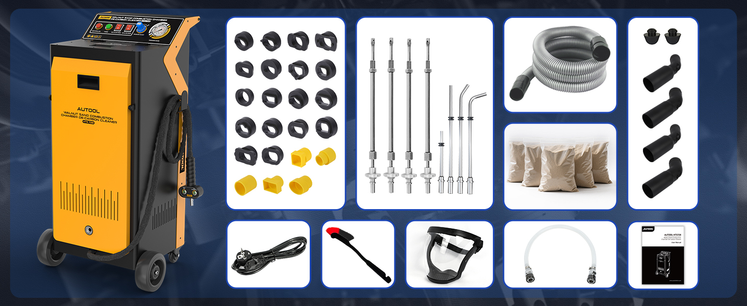
- the recovery hose, recovery elbow or connector, blasting handle, correct intake adapter or correct M12/M14 threaded nozzle for the actual application;
- eye or face protection, gloves, hearing protection, respiratory protection selected from the abrasive SDS and risk assessment, and effective workshop ventilation;
- port plugs, lint-free covers, suitable vacuum equipment, controlled air-cleaning equipment where approved, strong lighting, and a borescope;
- labeled storage for removed parts, new gaskets and seals, and vehicle-specific service tools.
The current exact manual specifies external air above 0.7 MPa with airflow above 0.4 m³/min, measured for the machine supply. Verify those requirements against the delivered nameplate and instructions, confirm the compressor can sustain the demand under flow, and never exceed the lowest pressure rating of the machine, hose, coupler, adapter, nozzle, or workpiece. Do not substitute a static tank-gauge reading for delivered airflow at the machine.
Place the HTS728 on a stable, dry, ventilated workshop floor. Confirm its nameplate voltage matches a grounded supply. Inspect the power cord, plug, switches, gauge, regulator, filter, cover, media tank, hoses, handle, nozzles, threads, seals, couplers, wheels, and brakes or chocks. Keep heat, flame, standing water, flammable vapor, and bystanders away.
Stop: Do not operate with a damaged electrical lead, missing ground, leaking air connection, blocked or missing filter, split recovery hose, wet or contaminated media, damaged nozzle thread, uncertain engine position, unprotected opening, or a recovery path you cannot prove.
Understand the HTS728 before loading media
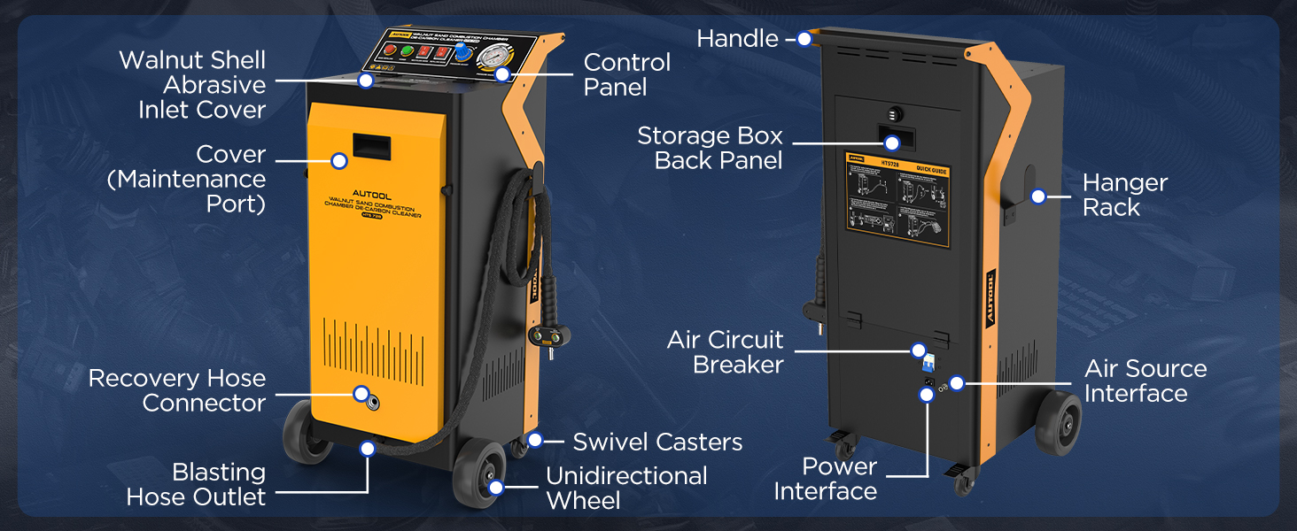
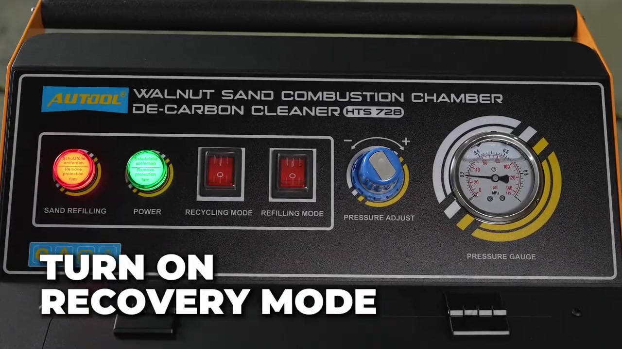
Identify the walnut-media inlet and top cover, pressurized blasting tank, recovery-hose connection, blasting-hose outlet, external-air interface, power inlet, maintenance cover, handle, wheels, and accessory storage. On the control panel, locate the Power indicator, Recovery mode switch, Filling mode switch, filling indicator, pressure regulator, and pressure gauge. On the hand control, identify the abrasive-blasting and air-only functions before either is connected to an engine.
The two machine switches do different jobs. Filling mode draws media from the lower storage area into the pressurized tank. Recovery mode powers the collection path used at the engine. The external compressor supplies the blasting energy. The hand control determines whether the selected nozzle delivers abrasive or air. Treat these as separate energy paths and confirm their state aloud during setup.
Trace the complete circuit with power and air isolated: compressor to machine and blasting handle; nozzle to the target area; target area to the sealed recovery adapter or connector; recovery hose back to the machine and filter. No amount of suction sound can compensate for an open route into the engine.
HTS728 step-by-step operating procedure
Step 1: Record the baseline and choose one cleaning path
Inspect the target with adequate light or a borescope and record the complaint, relevant diagnostic data, deposit location, engine condition, and intended path:
- Intake path: clean one exposed intake port and its closed intake valve while recovering at the same sealed port.
- Combustion-chamber path: clean through a spark-plug opening only with a vehicle-approved valve, piston, nozzle, and recovery arrangement.
Do not switch between these paths casually. Each has a different access method and contamination route. Define the required completion test before removing components.
Completion check: The diagnosis supports cleaning, the vehicle procedure permits the selected method, and the pre-cleaning condition and acceptance criteria are documented.
Step 2: Isolate the vehicle and protect every opening
Bring the engine to the condition specified by the vehicle procedure, usually fully cooled for this work. Disable ignition and fuel delivery as required and prevent unintended cranking. Remove the intake manifold for the intake path, or remove the approved spark plug for the combustion path, using the prescribed sequence. Keep dirt away from exposed threads, ports, connectors, lines, and sealing faces.
Count and label every removed fastener, connector, hose, seal, coil, and spark plug. Cover all openings that are not part of the active blast-and-recovery circuit. Do not use loose rags that can be drawn into a runner, and do not leave tools or abrasive containers above the engine.
Completion check: The engine cannot start unexpectedly, the active target is accessible, and every unintended opening is positively protected.
Step 3: Connect the recovery, blast, air, and power paths
With the HTS728 switched off, unplugged, and disconnected from compressed air, connect the recovery hose securely to the machine. Fit the appropriate recovery elbow or vehicle-specific connector at the work end. Assemble the blasting handle and the nozzle chosen for the exact path. Check that each seal seats squarely and that no hose is kinked or placed under strain.
Connect the dry, filtered air supply with the machine regulator backed down. Connect grounded power only after the air, blast, and recovery paths are mechanically secure. Keep both machine mode switches off and both hand-control functions released.
Common mistake: Selecting by vehicle badge or nozzle length. Match the actual port shape, thread, reach, seal, and recovery route; included parts are not universal.
Completion check: Every connection is secure, correctly rated, strain-free, and traceable from compressor to nozzle and from engine opening back to the filter.
Step 4: Load the specified walnut media
Confirm Recovery mode is off. With the blasting handle released, switch Filling mode on and open the top cover as the manual directs. Add only new, dry 0.4–0.6 mm walnut-shell abrasive. Brush remaining media from the lower storage area toward the inlet without putting a hand into a moving or pressurized system.
The exact HTS728 manual limits the load to no more than 3.5 kg. Close the top cover fully, remove the filling tool, then switch Filling mode off. Allow the storage opening to close and the pressurized tank to reach its required state before proceeding. Never open the cover while the tank is pressurized.
Stop: Do not mix particle sizes, add wet or oily media, exceed 3.5 kg, defeat a cover or interlock, or reach into the media path while the machine is energized.
Completion check: The correct dry media is loaded within the limit, the cover is closed, Filling mode is off, and the tank and filter path are ready.
Step 5: Prove recovery before enabling abrasive
Seat the recovery adapter or connector on a safe test arrangement or the prepared engine opening without enabling abrasive. Switch Recovery mode on and confirm stable suction. Check the entire hose, filter path, machine connection, adapter perimeter, and every protected opening for leakage, collapse, or movement.
Set the external-air supply and machine regulator only within the delivered instructions and the lowest component limit. The exact manual calls for supply pressure above 0.7 MPa; this is an inlet requirement, not permission to maximize nozzle pressure. Begin conservatively and confirm stable delivery under flow.
Pass condition: Recovery stays stable, the connector remains sealed, the hose does not collapse, neighboring covers remain secure, and no abrasive function is active.
Step 6: Choose one vehicle-supported cleaning path
Do not combine the intake and combustion sequences. Complete one target and pass its residual-media inspection before repositioning the crankshaft, opening another valve, moving to another cylinder, or changing adapters.
Path A — intake port and valve cleaning
Use vehicle timing information and direct observation to rotate the engine by the approved manual method until the exact target intake valve is fully closed. Do not use the starter motor. Confirm closure with the method specified for that engine; do not infer it from another cylinder or from vacuum sound.
Seal every other intake port. Seat the matched recovery adapter over the target port, insert the blasting nozzle through its intended opening, and support both hoses so the seal cannot lift. With Recovery mode already stable, enable abrasive in short, controlled passes. Sweep the nozzle across approved surfaces without striking the valve, seat, stem, guide, runner wall, or sealing face.
Release abrasive before changing angle or adapter position. Inspect after each pass. The manual’s approximate two-minute example is an inspection point, not a universal duration; deposit hardness, access, airflow, media condition, and vehicle limits differ.
Stop: Stop immediately if the valve position becomes uncertain, the adapter leaks, recovery weakens, media escapes, the nozzle contacts metal, liquid appears, or the engine opening changes.
Completion check: The approved deposit is removed without visible surface damage, the valve remained closed, and blast and recovery stayed controlled.
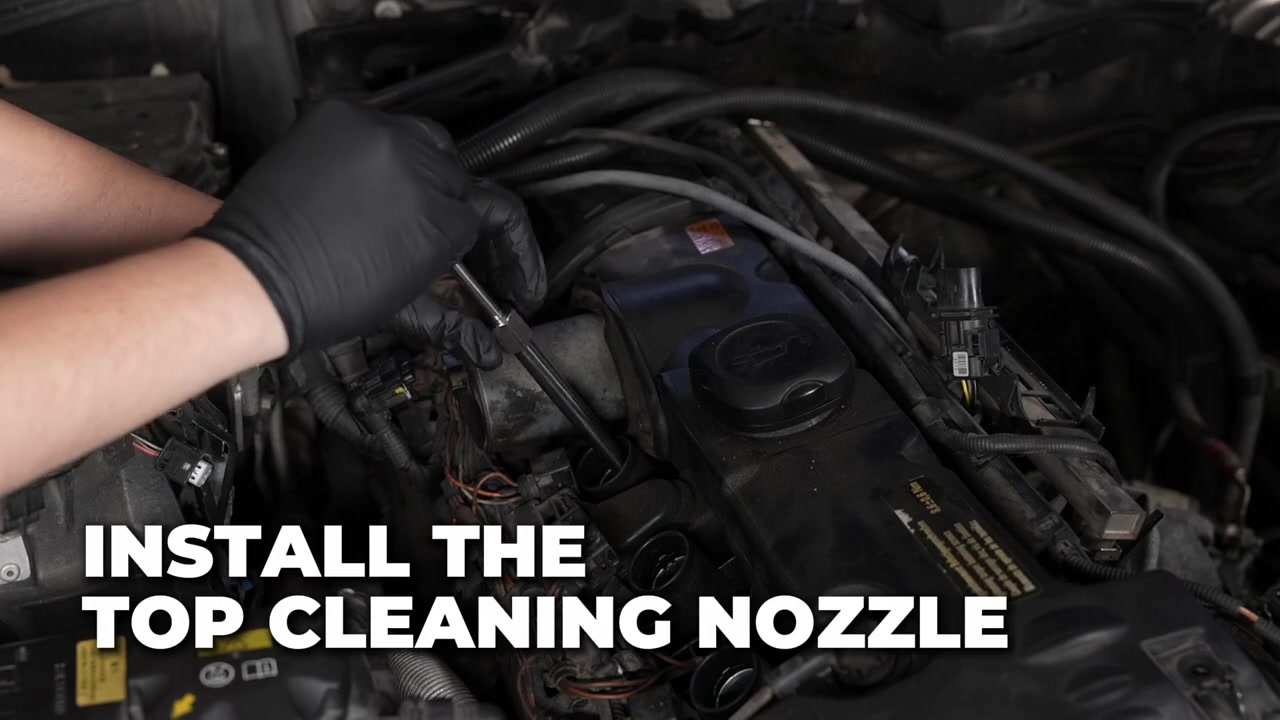
Path B — combustion chamber through a spark-plug opening
Use this path only when the vehicle service information explicitly supports abrasive cleaning through the spark-plug hole and defines a safe route for recovering the media. Confirm the target cylinder, piston position, valve state, and crankshaft restraint from that procedure. The intake-port rule of “intake valve fully closed” must not be copied here; the required valve state depends on the approved recovery route through the chamber.
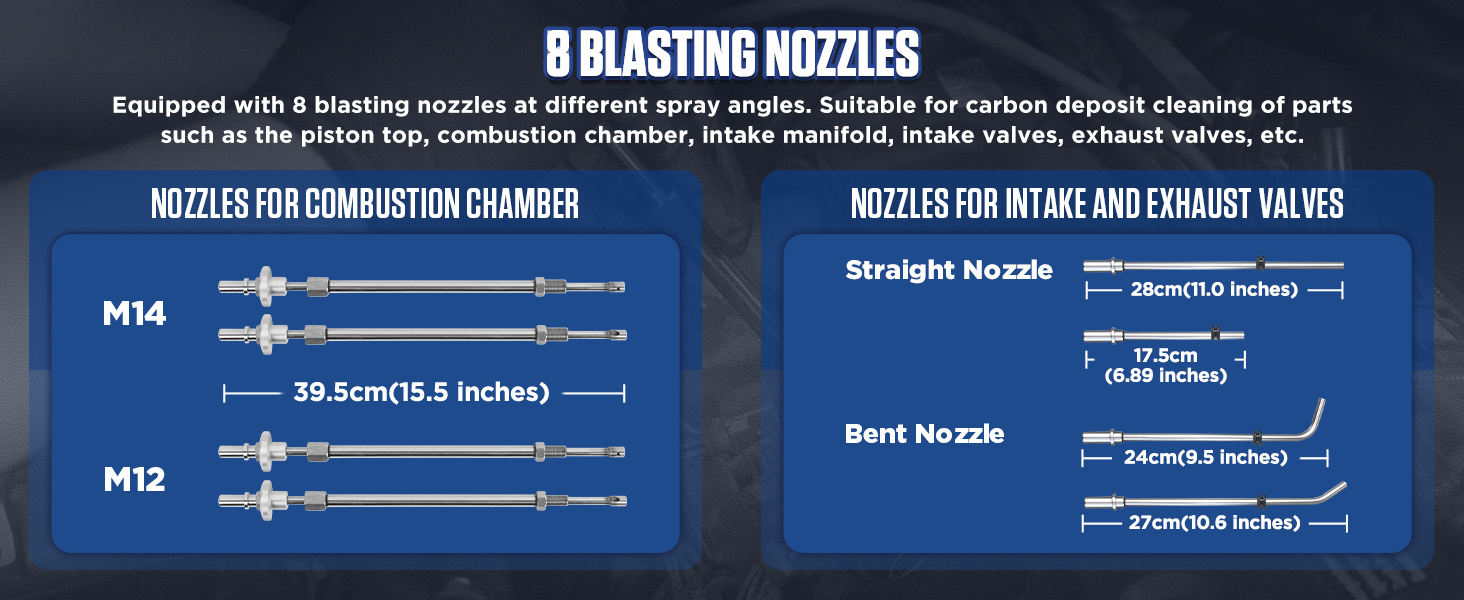
Inspect the plug well and threads, then select the correct M12 or M14 nozzle by the actual spark-plug thread and reach. Start the threaded adapter by hand, keep it square, and stop for resistance. Never force, cross-thread, bottom, or improvise a seal. Attach the recovery hose to the exact port or connector specified for the chamber-cleaning circuit and protect all other openings.
Prove stable recovery through the intended chamber route before abrasive flow. With Recovery mode on, use short blasting cycles and controlled nozzle depth. Release abrasive before repositioning. Where the exact setup and vehicle procedure permit the hand control’s air-only function, use it only after abrasive flow stops and while recovery remains established. Never rotate the engine, change valve position, or move to another cylinder while loose media may remain.
One demonstrated HTS728 sequence uses recovery, short blasting, air-only clearing, and a borescope check on a specific engine. Treat that sequence as control orientation only: nozzle depth, valve position, cycle time, and recovery connection must come from the procedure for the engine in front of you.
Stop: Stop for uncertain piston or valve position, a poor thread seal, weak recovery, nozzle contact, escaping media, unexpected liquid, inability to see the result, or any vehicle procedure that does not authorize this path.
Completion check: The supported chamber surfaces meet the visible cleaning criterion, the nozzle and threads are undamaged, and the full recovery route remained controlled.
Step 7: Control the hand-piece functions deliberately
Keep a firm two-hand position that does not load the adapter or spark-plug thread. Confirm the abrasive and air-only controls by touch and label before use. Enable only the intended function, release it before changing nozzle depth or direction, and keep Recovery mode running throughout the cleaning cycle.
Use the lowest effective controlled setting. Increasing pressure is not a cure for wet media, a blockage, bad seal, full filter, kinked hose, wrong nozzle, or unsuitable deposit. If flow pulses or stops, release the control, isolate air and power, depressurize according to the manual, and troubleshoot away from the open engine.
Completion check: Abrasive and air-only functions respond separately, the nozzle moves without contact, and recovery remains stable through every short pass.
Step 8: Inspect after each short cycle
Release abrasive, keep recovery active, and inspect the same target under consistent light and angle. Use a borescope where direct sight is limited. Look for remaining deposit, exposed surface condition, fluid, damage, loose debris, and walnut media in recesses.
Do not chase cosmetic perfection at the cost of a coating, valve edge, thread, seat, guide, piston crown, or cylinder wall. Stop when the vehicle-approved surface condition is reached. If the deposit does not respond, reassess the diagnosis, media delivery, access, and whether this is the correct method.
Completion check: The result is visible and documented, underlying surfaces remain intact, and another pass is justified by evidence rather than elapsed time.
Step 9: Repeat one opening at a time
Finish and protect the current opening before moving to the next. For intake work, recover all loose media before rotating the crankshaft, then prove the next target valve fully closed. For chamber work, pass the complete residual check before changing piston or valve position or transferring the nozzle to another plug hole.
Recheck the adapter or thread fit, recovery seal, filter airflow, media condition, pressure behavior, and neighboring protection at every move. Use comparable before/after views for each target.
Completion check: Every serviced port or cylinder has its own setup confirmation, cleaning record, residual-media check, and final image.
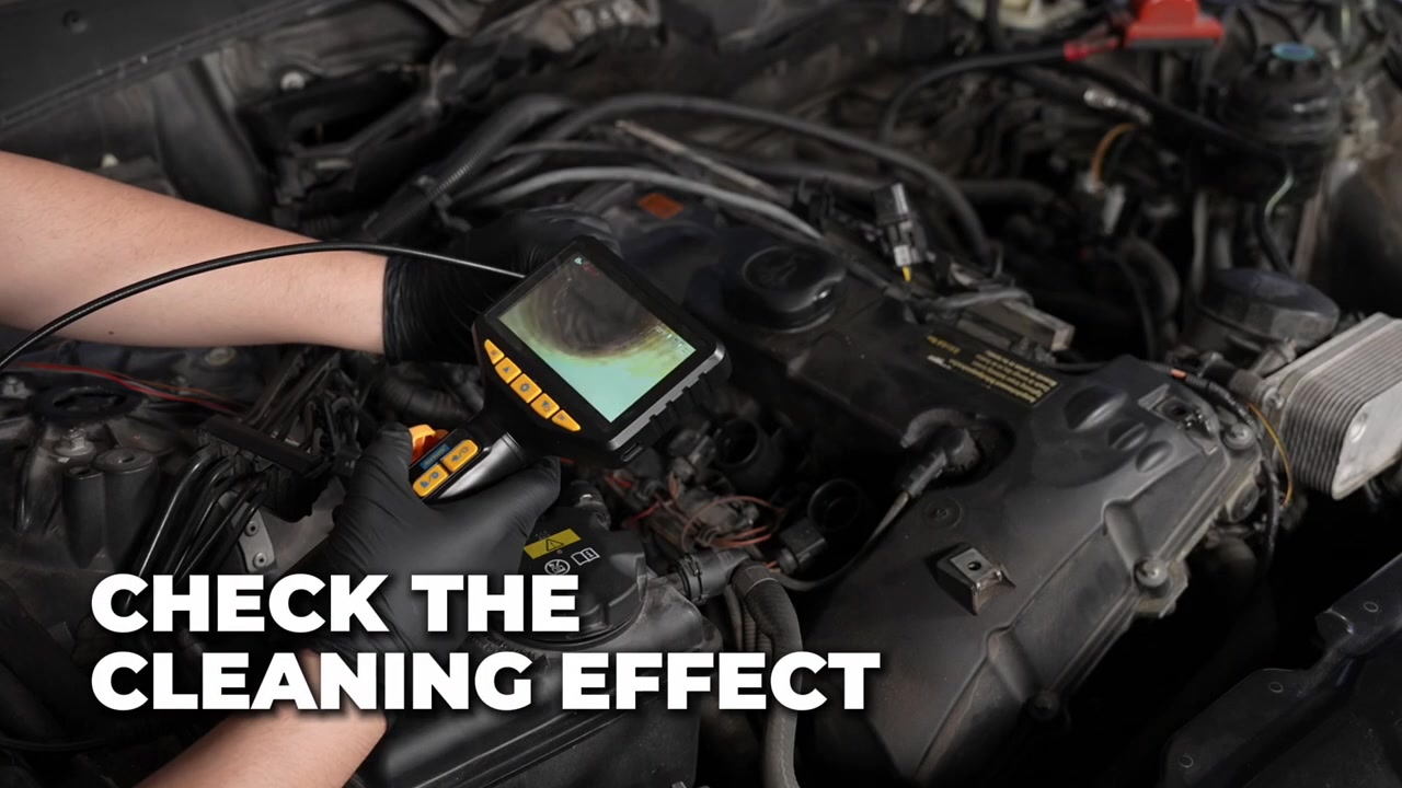
Step 10: Recover every particle and inspect
Release abrasive and any air-only control while keeping Recovery mode on. Sweep the recovery connection through the approved positions, then use suitable vacuum equipment, controlled air only where permitted, strong light, and a borescope to inspect the target, edges, recesses, neighboring openings, plug threads, and sealing faces.
Do not rely on walnut media burning harmlessly after restart. Visible particles must be removed. If you cannot see or reach an area where media may be trapped, do not rotate or start the engine; restore access or use an approved recovery method until the residual check passes.
For combustion-chamber work, inspect the piston crown, accessible cylinder wall, valve area, and plug opening through a full viewing sweep. Follow the vehicle procedure for any approved hand rotation and repeat the inspection afterward. For intake work, inspect the runner, valve pocket, valve face and perimeter, and adjoining ports.
Pass condition: No visible loose abrasive or carbon debris remains in any serviced or neighboring opening, and the result is documented before reassembly.
Step 11: Shut down and depressurize the HTS728
With both hand controls released, switch Recovery mode off. Close the external air supply, safely bleed trapped pressure, verify the gauge and system are depressurized, then disconnect the air line. Switch off and unplug the machine. Do not open the media cover, filter area, hose, or nozzle path while pressure or electrical energy remains.
If the pressurized tank needs more media during a job, follow the manual’s sequence: stop the blasting control, switch Filling mode on so the tank automatically depressurizes, wait until depressurization is complete, switch Recovery mode off, then open and refill only after verifying zero pressure. Never use the cover as a pressure-release device.
Completion check: Abrasive, air, pressure, recovery, and electrical energy are all isolated before the machine or vehicle is opened further.
Step 12: Reassemble and validate the vehicle
Account for every plug, cover, tool, fastener, coil, connector, and seal. Clean mating surfaces only by the approved method. Install new gaskets, seals, and spark plugs where required, applying the specified sequence and torque. Reconnect fuel, ignition, vacuum, crankcase-ventilation, coolant, electrical, and intake components exactly as documented.
Restore power and fuel only after the residual-media and tool counts pass. Perform the required scan, adaptations, leak checks, compression or leak-down check where specified, idle check, live-data review, and functional or road test. Compare the result with the baseline; do not promise power, fuel economy, or fault correction from appearance alone.
Completion check: Reassembly is leak-free, no new fault is present, required data meet the vehicle procedure, and the service record links the outcome to the original complaint.
How to judge the result
Use four gates:
- Surface gate: the specified deposit is removed without visible damage to the valve, seat, guide, port, plug thread, piston, cylinder, coating, wiring, hose, or sealing face.
- Recovery gate: no visible walnut media or loosened carbon remains in the target, neighboring openings, intake tract, plug well, or engine bay.
- Assembly gate: every protection item and tool is accounted for, required seals are renewed, and fasteners and plugs are installed to specification.
- Vehicle gate: leak, scan, live-data, idle, and other required checks pass without a new fault.
A clean borescope image proves only what that view shows. It does not prove valve sealing, ring condition, injector performance, compression, or the cause of every symptom. Continue diagnosis when the original complaint remains.
Common HTS728 mistakes
Using one valve-position rule for both cleaning paths
An intake port requires its target intake valve closed. A combustion-chamber recovery route may require a different, vehicle-specific valve arrangement. Define the path from the vehicle procedure before abrasive is loaded.
Treating the inlet-pressure figure as a target to maximize
The manual’s external-air requirement describes supply capability. Use the regulator conservatively and stay within every component and vehicle limit. Fix restrictions and leaks instead of compensating with pressure.
Loading the wrong media or too much media
HTS728 specifies dry 0.4–0.6 mm walnut abrasive and no more than 3.5 kg. Different HTS models use different media specifications; do not copy a bag or fill amount from another machine.
Forcing a threaded chamber nozzle
Confirm M12 or M14 thread, reach, seat, and vehicle approval. Start by hand and stop at resistance. A nozzle that reaches the chamber can still damage a plug thread or contact a piston or valve.
Using a fixed two-minute timer as the acceptance test
The manual gives approximately two minutes before inspection, not a guarantee. Work in controlled passes and stop when the approved visible result is reached.
Restarting because walnut shell is combustible
Combustibility is not a recovery method. Continue vacuum recovery and visual or borescope inspection until no visible particle remains.
HTS728 maintenance after the job
After pressure and power are isolated:
- manage used abrasive according to its contamination, SDS, vehicle procedure, and local rules;
- inspect and service the filter and lower screen without contaminating the clean side;
- clear the blasting handle, air-only passage, nozzles, recovery connector, hose, adapters, and couplers by the approved method;
- inspect plug-nozzle threads, seals, hose walls, cable, switches, regulator, gauge, cover, latches, wheels, and handle;
- keep corrosive liquid away from the machine and never wash electrical or pressure components by immersion;
- store the HTS728 dry, unplugged, depressurized, and protected from heat, moisture, impact, and unauthorized use.
Never operate the recovery system without its filter. Have damaged electrical, pressure, or threaded parts repaired or replaced by qualified service; do not tape, splice, grind, or improvise a safety-critical part.
Frequently asked questions
Does HTS728 include an air compressor?
No. The machine powers its recovery and media-handling functions, but walnut blasting requires a compatible external source of dry, filtered compressed air.
What walnut media does HTS728 use?
Use new, dry 0.4–0.6 mm walnut-shell abrasive. Do not substitute the larger media specified for some other HTS models.
How much walnut media can I load?
The exact manual states no more than 3.5 kg. Keep the correct particle size dry, close the cover fully, and never open the tank while it is pressurized.
What air supply does the manual require?
The exact manual specifies external air above 0.7 MPa and airflow above 0.4 m³/min. Verify this at the machine under flow, follow the delivered nameplate and instructions, and never exceed the lowest-rated component or vehicle limit.
Can HTS728 clean through a spark-plug hole?
It supports that configuration, but only use it when the exact vehicle procedure authorizes abrasive chamber cleaning and defines the piston, valve, nozzle, and recovery arrangement. Physical access alone is not approval.
Should the intake valve be open or closed?
For intake-port cleaning, the target intake valve must be fully closed. For combustion-chamber cleaning, follow the exact valve arrangement required to establish the approved chamber recovery route; do not copy the intake rule.
How do Recovery mode and Filling mode differ?
Recovery mode powers the collection path at the engine. Filling mode transfers walnut media into the pressurized tank and is also part of the manual’s depressurization-and-refill sequence. Do not treat them as interchangeable operating modes.
Can the included nozzles fit every engine?
No. Confirm the port geometry or spark-plug thread, reach, sealing method, component clearance, and vehicle approval for the actual engine.
Can recovered walnut abrasive be reused?
Do not assume it is suitable. Recovered media may contain carbon, oil, metal, moisture, or other debris. Use fresh dry media as the controlled default unless the current instructions, media condition, vehicle procedure, and local handling rules all permit reuse.
What must happen before the engine turns or starts?
No visible abrasive can remain; all protection and tools must be accounted for; the approved inspection must pass; and reassembly, torque, leak, scan, and functional checks must be complete. Never rotate or start an engine to dispose of media you could not recover.
The reliable HTS728 workflow
The dependable sequence is: diagnose, choose one approved path, isolate the vehicle, protect every unintended opening, connect and prove recovery, load the correct media, blast in short controlled passes, inspect, recover every visible particle, depressurize, reassemble, and validate. HTS728 provides flexible intake and supported chamber-cleaning hardware; safe results depend on never confusing those two paths and never allowing a shortcut around the residual-media gate.











Comments 0
Questions, fixes, and real-world diagnostic notes from readers.
Be the first to share a diagnostic result or ask a follow-up question.