
How to Assemble and Commission the AUTOOL XC505 3D Wheel Aligner

A precise wheel alignment begins before any vehicle reaches the turntables. The AUTOOL XC505 3D wheel aligner must be installed on a suitable bay, assembled without stressing its camera beam, connected correctly and checked for an unobstructed view of all four targets. This guide takes a new owner from unopened crates to a controlled commissioning check.
Quick answer: Match both crate serial numbers, approve the lift and installation environment, assemble the cart and target storage, erect and anchor the column, connect the beam’s USB and power cables with power isolated, then confirm that the software can see all four correctly labelled targets. Do not open or adjust the cameras to correct a setup problem.
In this guide
What this commissioning guide covers
Commissioning means proving that the workstation is mechanically stable, electrically safe and able to acquire all four target images. It is not the same as performing an alignment, and it does not include modifying factory camera settings.
The XC505 is precision measuring equipment. The column, beam and cameras must not be treated like ordinary shop furniture: a twisted enclosure, unstable base, blocked target or poor lighting condition can make good software data impossible. Plan the bay first and assemble the hardware once.
| Commissioning item | Source-controlled requirement | Pass condition |
|---|---|---|
| Power | Grounded three-pin AC 110–240 V, 50/60 Hz | Stable supply and intact earth connection |
| Lift | Installed, fixed and level; front-to-end platform difference under 5 mm | No rocking, obstruction or excessive height difference |
| Environment | No vibration, moisture, direct sun or direct infrared light on targets | Clean sightline from both cameras to all targets |
| Beam links | USB data cable plus power-supply cable | Both secured without pinch, strain or loose routing |
| Targets | Four position-labelled targets | Correct FL, FR, RL and RR identity and clean surfaces |
After this commissioning check passes, use the complete XC505 wheel-alignment operating guide for vehicle preparation, rolling compensation, measurement and adjustment workflow.
Before you start
- Arrange a qualified installer and a second person or suitable lifting equipment for the column and camera beam.
- Isolate mains power while mechanical parts and internal cables are being fitted.
- Confirm that the alignment lift is installed, fixed, level and clear on every side.
- Prepare the packing list, installation hardware and correct tools; do not substitute anchors or fasteners by guesswork.
- Check that the bay has a grounded three-pin outlet and stable AC supply within the rated range.
- Control direct sunlight and infrared sources, and keep water, grinding dust and impact work away from the targets and cameras.
If the floor, lift, supply or lifting plan is not ready, stop here. Assembly should not be used to discover whether the bay can support the machine.
XC505 assembly and commissioning steps
Step 1: Match the two crates and inspect the delivery
Read the factory serial number on each wooden crate before removing parts. The official assembly sequence starts by confirming that the two numbers match, because the column/beam and workstation components belong to the same delivered system.
Open the crates without dragging tools across painted panels, target faces or camera filters. Compare every part with the packing list and record shipping damage before assembly. Set precision parts on a clean, padded surface rather than on the alignment rack or bare floor.
Step 2: Approve the bay and lift geometry
Verify the lift is securely installed and level before locating the aligner. The manual specifies a front-to-end lift-platform height difference of less than 5 mm. Clear the operating space so the cart, clamps and technician can move without crossing the vehicle path.
Look from the proposed beam position toward all four target locations. Direct sunlight, direct infrared light, posts, open hoods and stored equipment must not interrupt that view. Do not place the column on a vibrating machine base, a sloping surface or a wet area.
Step 3: Build the mobile workstation
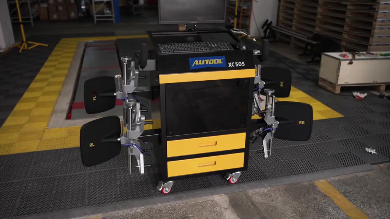
Fit the wheel-clamp holders to the cart, then install the cart handle and monitor holder in the orientation shown by the supplied hardware. Seat the monitor securely before routing its cable; a cable should reach its port without supporting the monitor’s weight or rubbing a drawer edge.
Place the computer, keyboard, mouse and printer in their intended positions. Route peripheral leads through the provided openings and leave enough service loop for the cart to move, but no loose loop that can catch a clamp or caster. Keep mains power disconnected during this work.
Step 4: Mount and identify the four clamp-and-target sets
Mount each wheel clamp on its holder and store its target with the correct position label facing outward. The four positions are front left, front right, rear left and rear right. Keeping this identity visible now prevents a rushed technician from swapping targets at the vehicle.
Handle a target by its frame. Do not press, scratch or place tools against the patterned face. Leave shipping or dust protection in place while column work is underway, and clean only with the method permitted by the manual.
Step 5: Assemble the column cap and lateral beam
Support the beam throughout installation. Fit the column cap and beam components squarely, starting fasteners by hand before final tightening. If holes do not align, reposition the supported parts instead of forcing the extrusion or using bolts to pull a twisted assembly together.
Protect both cameras from contact while the beam is being handled. The camera housings and filters are precision parts, so they are not lifting points, handles or surfaces on which to rest the beam.
Step 6: Erect and secure the column
Use the planned lifting method to raise the assembled column without allowing the beam to swing. Position the base on the approved floor geometry, confirm that the column is upright and install the specified anchoring hardware. Use the installation documentation or qualified site engineer for anchor type, drilling depth and torque rather than generic values.
Recheck clearance to the lift and the camera sightline before finalizing the base. Once the commissioned position is established, do not move the column as a shortcut for solving a target-view problem.
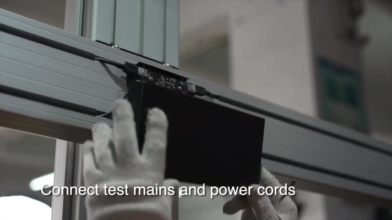
Step 7: Connect beam data and power with mains isolated
Open the rear cover at the center of the lateral beam. Identify the USB data cable and the beam power-supply cable, connect each to its matching interface and inspect the connector seating. These are separate functions; a powered beam does not prove that the computer has a data link.
Route the cables so raising, lowering or normal shop movement cannot pinch, pull or abrade them. Close the cover only after a second visual check. Connect the workstation to a grounded three-pin supply only when all mechanical and internal connection work is complete.
Step 8: Remove protection and inspect the optical path
Remove target and camera dust protection only after drilling, anchoring and assembly debris have been cleared. Inspect the camera filters and target faces under clean light. Dust, fingerprints and reflective contamination can affect image acquisition even when no part looks physically damaged.
Place the four labelled targets where both cameras have an unobstructed view. Eliminate direct infrared or sunlight at the target plane. Do not open a camera housing or turn an internal adjustment to compensate for poor bay conditions.
Step 9: Power up and verify every workstation device
Switch on the protected supply, computer and XC505 in the prescribed order. Confirm normal startup of the monitor, keyboard, mouse and printer before opening a customer job. A peripheral fault is easier to isolate now than while a vehicle is occupying the rack.
Open the alignment software and use its target-monitor view. Confirm that all four position-labelled targets appear consistently and that no blocked-target warning remains. If a target is missing, check identity, lighting, obstruction, cleanliness, USB connection and cable condition first.
Step 10: Perform a controlled dry commissioning check
With the bay empty or under the controlled procedure specified for the shop, move around the rack and verify that the column, cart and cables remain stable and clear of travel paths. Confirm that turntables, passing bridges, steering-wheel holder and brake-pedal depressor are present and stored safely.
Record the serial number, installation date, supply check, lift-level check, four-target visibility and peripheral results. Release the XC505 for alignment work only when every item passes. If geometry or image acquisition still fails, stop and obtain installation support rather than changing camera alignment.
How to judge the commissioning result
A finished-looking workstation is not enough. Use observable pass conditions so the first alignment is not also the installation test.
| Check | Pass | Stop and correct |
|---|---|---|
| Mechanical | Column and beam stable; cart rolls and parks safely | Movement, distortion, loose hardware or obstructed vehicle path |
| Electrical | Stable startup from grounded supply | Intermittent power, damaged earth, hot connector or repeated restart |
| Data | Computer communicates with beam | Powered cameras but no data or recurring disconnect |
| Optical | All four labelled targets remain visible | Blocked warning, glare, dirty target or missing position |
| Peripheral | Monitor, input devices and printer respond | Any device prevents job selection, control or report output |
The XC505 is factory calibrated, but factory calibration does not correct an unsuitable floor, moving column, blocked target or damaged cable. Never open or adjust a camera to make an installation pass; isolate the fault and use qualified service support.
Common mistakes
- Uncrating both boxes without first matching their factory serial numbers.
- Anchoring the column before the lift, sightline and service clearances are approved.
- Using camera housings or the beam extrusion as lifting handles.
- Mixing FL, FR, RL and RR targets because position labels were hidden in storage.
- Treating electrical power as proof that the USB data link is working.
- Removing optical dust protection before drilling and cleanup are finished.
- Trying to solve sunlight, obstruction or poor lift geometry by moving the column or adjusting a camera.
Frequently asked questions
Does the AUTOOL XC505 need on-site camera calibration after assembly?
The manual states that the system is accurately calibrated during manufacturing and does not require on-site calibration at installation. Install it to specification and verify target visibility; do not open or adjust the cameras.
Which cables connect the computer and camera beam?
The manual identifies two links: a USB data cable and a power-supply cable. Both must be connected and protected from strain or damage.
Why can all four targets be clean but still show as blocked?
Check the complete optical path. A vehicle panel, lift post, tool cart, direct sunlight or infrared source can prevent reliable capture. The target-monitor screen helps identify the affected position.
Can I install the XC505 beside any existing alignment lift?
Only after confirming the lift is fixed, level and compatible with the required sightline and working space. The XC505 manual specifies less than 5 mm front-to-end platform height difference.
What should be recorded at handover?
Record the paired serial number, installation date, lift and power checks, cable inspection, four-target visibility, peripheral operation and the person who accepted the system.
XC505 handover checklist
- Both crate serial numbers match and the packing list is complete.
- Lift, bay, lighting and grounded power meet the installation conditions.
- Column, beam, cart, monitor and holders are secure with no distortion.
- USB data and beam power cables are seated, protected and covered.
- Targets are clean, position-labelled and visible to both cameras.
- Computer, monitor, keyboard, mouse, printer and target monitor all pass.
- Installation results are recorded before the first customer alignment.
A disciplined XC505 installation creates a repeatable reference for every job that follows: a stable lift, a fixed camera relationship, clean labelled targets and a verified data path. Once these commissioning checks pass, the normal vehicle-alignment workflow can begin with confidence.









Comments 0
Questions, fixes, and real-world diagnostic notes from readers.
Be the first to share a diagnostic result or ask a follow-up question.