
How to Install and Use the MRCARTOOL M95 GPS Inclinometer

The MRCARTOOL M95 GPS slope meter combines a round color display, multi-axis angle sensing and satellite-derived driving information. Its exact product material shows speed, clock, course angle, altitude, coordinates, compass, mileage, satellite count, driving time, voltage, pitch and roll. The installation succeeds only when power, GPS reception and the physical angle reference are checked separately.
Quick answer: Start with normal tire pressures, ride height and vehicle load, then park on a surface verified level in both directions. Dry-fit the M95 on a rigid dashboard area, square with the vehicle centerline and below the normal road view. Use the supplied cigarette-lighter power cable for an initial reversible installation; reserve the supplied retrofit lead for a qualified installer. Route all wiring away from pedals, steering, seats and airbags. Power on outdoors, wait for stable satellite time, position, direction and speed, then establish the pitch-and-roll reference using only the exact instructions supplied with the unit. Review alarms and units while parked and verify mount, baseline and shutdown behavior after a short controlled drive.

In this guide
What the M95 measures—and what it does not
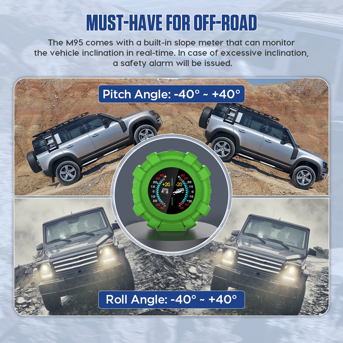
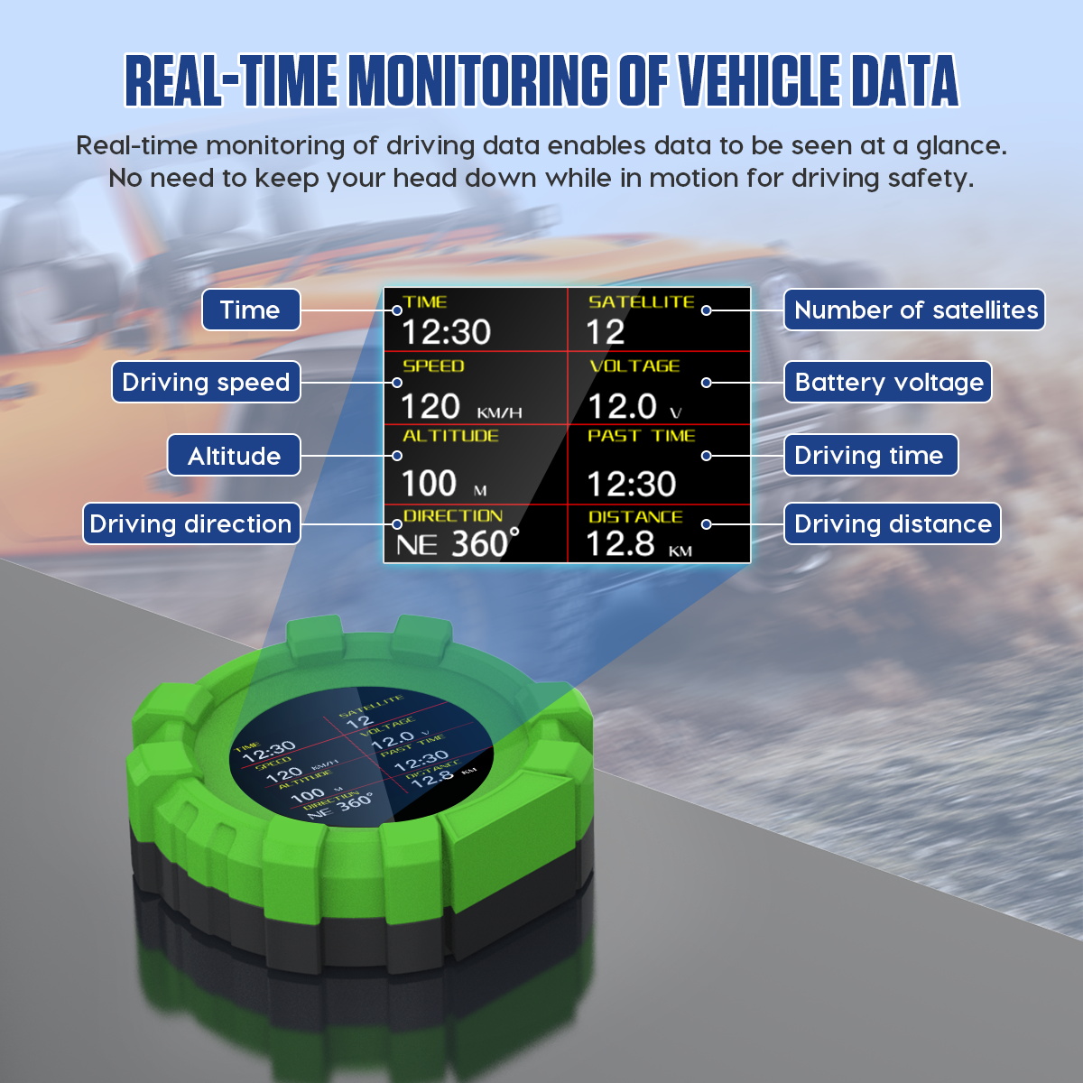
The M95 contains two distinct measurement systems. Its GPS receiver supplies location-dependent information such as speed, time, altitude, longitude, latitude, compass/course direction, satellite count and trip distance. Its internal multi-axis sensor supplies pitch and roll. Accessory-circuit voltage can also appear on the interface. This separation matters: a lost GPS fix can stop speed or coordinates while the angle graphic still moves, and a shifted dashboard mount can corrupt angles while satellite fields remain normal.
The product text includes an engine-RPM item, yet the retained exact package list shows cigarette-lighter and retrofit power leads rather than an OBD data cable, and the official interface graphics do not identify RPM. This guide therefore does not promise an RPM reading. The page also markets broad vehicle suitability, but practical compatibility still depends on a safe electrical connection, acceptable mounting location and correct local rules for dashboard accessories.
Do not use an angle number as permission to continue. The M95 cannot measure tire grip, soil strength, side-slip, suspension travel, load movement or dynamic rollover risk. Its overspeed, fatigue and excessive-inclination alarms are prompts only. Vehicle limits, road conditions, regulations and driver judgment remain controlling.
Prepare the vehicle
1. Establish a repeatable vehicle condition
Set tire pressures to the vehicle specification and inspect for a visibly low tire, altered ride height or suspension fault. Remove temporary uneven loads unless they represent the normal operating configuration. Close doors and settle the suspension. Record the load state because moving tools, passengers, roof cargo or a trailer can change the vehicle body angle even when the ground has not changed. The angle baseline is meaningful only when the installation condition is reproducible.
2. Find ground that is level in both axes
A parking bay that looks flat may include drainage fall. Check both longitudinal and lateral level with a suitable reference or use a verified workshop surface. Do not create the zero point with one wheel on a curb, soft ground or a ramp. Pointing the vehicle in the opposite direction on the same surface is a useful reasonableness check: a large change suggests the ground, vehicle or mounting reference needs attention.
Mount and power the display
3. Dry-fit the round housing
Sit in the normal driving position and place the M95 low on a rigid dashboard section. Its distinctive round body can make visual alignment deceptive, so use the display axes or a straight case reference rather than judging from the outer green ring alone. Align it square with the vehicle centerline. Check the windshield view, instrument cluster, warning lamps, vents and automatic-light sensor, then inspect all nearby airbag seams before removing the tape liner.
4. Choose reversible or fixed power
The package list identifies a cigarette-lighter power cable and a mini retrofit power cable. Begin with the cigarette-lighter connection when possible because it lets you verify position, reception, startup and shutdown without altering vehicle wiring. Connect only while parked and keep the plug accessible. If the socket is constant-power, the unit may remain energized after key-off; actual sleep behavior must be observed rather than assumed.
A fixed ACC installation requires verified switched power, correct polarity, suitable circuit protection and a route that does not interfere with vehicle systems. Have a qualified installer use vehicle wiring information and appropriate test equipment. Do not tap restraint, safety, communication or unidentified wiring. The retained exact product page does not publish an input-voltage range, fuse value or pinout, so none should be guessed from another M-series product.
5. Route and secure the cable
Follow fixed trim and preserve a gentle bend at the device connector. Keep wiring out of pedal travel, steering-column movement, knee space, airbag deployment paths, seat tracks, parking-brake mechanisms, hot ducts and sharp metal edges. Leave controlled service slack without a hanging loop. Cycle pedals, steering, seat and column through their ranges while stationary. Only then clean the mounting surface with a material-safe method, apply the supplied tape and hold the base without twisting it.
Verify GPS reception
6. Power on in open sky
Move outdoors away from garages, metal roofs, dense trees and tall buildings. Wait stationary while the receiver establishes a fix. Do not treat a displayed zero speed as proof of acquisition. Instead, confirm several independent signs: satellite count becomes populated, satellite time is plausible, coordinates settle, altitude stops making large jumps and direction behaves logically once the vehicle moves. A cold acquisition can take longer than a recent restart, and the exact page does not promise a fixed acquisition time.
GPS course direction often requires motion, so a compass arrow that wanders while stationary is not necessarily a defect. Tunnels, covered parking, steep valleys and urban canyons can interrupt or reflect signals. Coordinates and altitude are suitable for orientation and trends, not survey work or emergency-grade positioning. When reception degrades, continue to use required vehicle instruments and appropriate navigation instead of chasing the display while driving.
Reference pitch and roll
7. Set the reference only with exact instructions
With the vehicle stationary on the verified level surface and the housing square, follow the user manual supplied with this exact M95 to establish its angle reference. No downloadable exact manual or exact official tutorial video was available in the retained sources, so this guide does not invent a button, menu or press duration. Keep your hand from rotating or tilting the housing during the command, then release it and allow both axes to settle.
8. Verify direction and repeatability
Under a mild controlled condition, confirm that left-versus-right body movement changes roll in the expected direction and uphill-versus-downhill movement changes pitch. Return to level ground and compare the baseline. Repeat once after repositioning the vehicle. If the value does not return, inspect the tape, dashboard flex, housing rotation, tire pressures, suspension and load before zeroing again. Repeatedly removing an offset can hide a moving mount.
Interpret the driving information
9. Compare speed under stable conditions
Wait for stable reception, then compare GPS speed on a straight open road at a steady legal speed. A passenger should record values so the driver stays focused. Avoid acceleration, braking, curves and moments immediately after signal recovery because update timing can make two valid displays differ briefly. If the M95 provides a speed-adjust option, record the original value and change it only after a repeatable offset is proven. The vehicle’s required speedometer remains controlling.
10. Treat trip fields as convenience records
Driving time, current distance and total mileage depend on the unit’s start, sleep and reset behavior. They may not match the odometer, service interval or legal distance record. Establish a known short route to learn when a trip starts and stops, then observe what remains after key-off. Do not clear a total or restore settings without recording the current values and understanding what data will be lost.
11. Read voltage at the accessory path
The M95 interface graphic labels battery voltage, but the display is electrically connected through its accessory power path. Connector resistance, wiring length, circuit load and a retrofit connection can make that value differ from a calibrated battery-terminal measurement. Use it to notice trends or gross changes. Diagnose charging, starting or battery health with suitable equipment at the vehicle’s specified test points.
12. Check automatic brightness
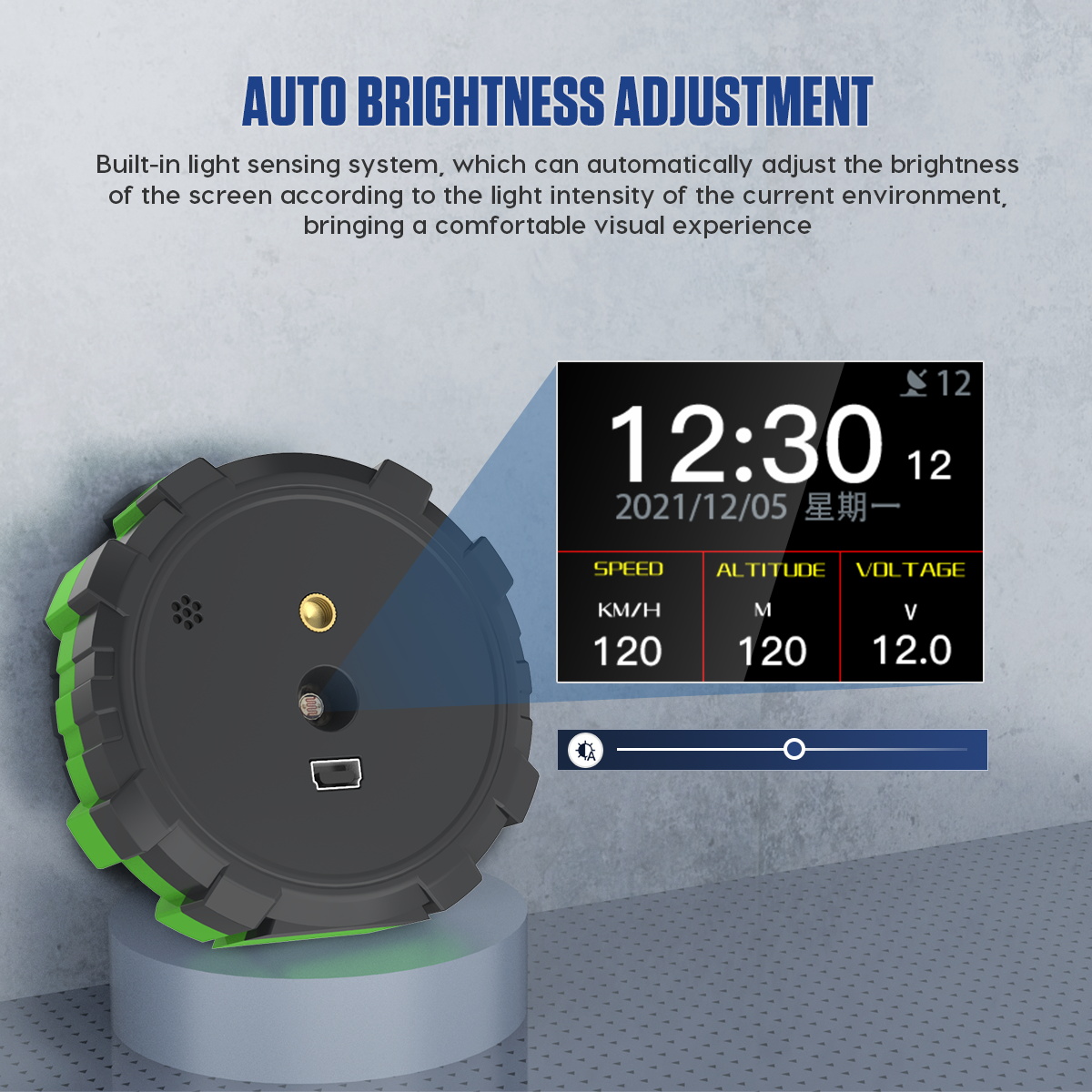
The page says the built-in light sensor adjusts screen brightness to current light. Shade and expose the sensor while parked and look for a controlled change. If it does not respond, first check that the mounting position, hand, cable or trim is not covering the sensor. At night, choose a position and brightness that remain readable without reflecting in the windshield or drawing attention away from the road.
Configure alarms conservatively
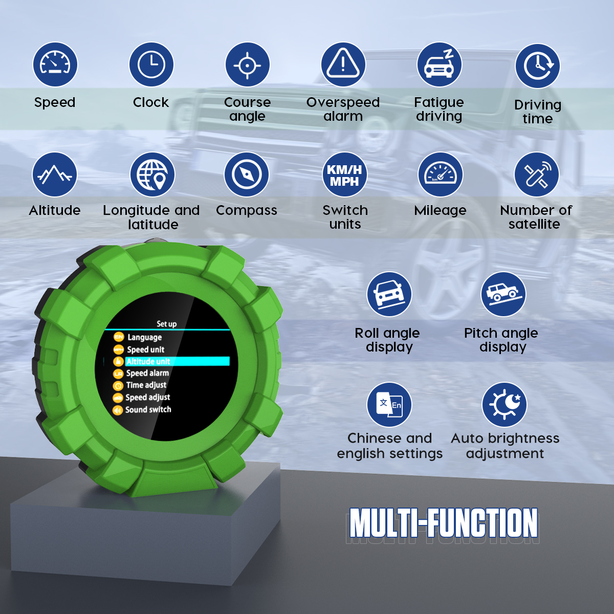
The exact page lists overspeed, fatigue-driving and excessive-inclination alerts but does not provide their full button sequence or safe threshold guidance. Configure speed units before entering an alarm value, and choose a threshold consistent with applicable law and operating policy. Treat the fatigue alert as a reminder to stop, never as evidence that continued driving is safe. Never approach a steep side slope merely to trigger the inclination alarm.
Review language and units before adjusting any numerical value. Record the original settings with a photo or written note, change one item, exit the menu and verify the result. If the interface differs from a product graphic, follow the exact firmware and printed manual supplied with the unit. Avoid a factory restore unless necessary because it can clear calibration, trip data or preferences.
Recheck after the first drive
After a short controlled drive, park safely and inspect the complete installation. Confirm the base has not rotated, the cable has not migrated toward controls, the power plug remains cool and secure and the screen still has a clear sky view. Return to verified level ground and compare the angle baseline. Switch the vehicle off and observe whether M95 follows the expected shutdown or hibernation behavior. Disconnect it if a constant-power circuit keeps it awake or creates battery concern.
Troubleshoot the M95
| Symptom | Check first |
|---|---|
| No power | Accessory socket or protected ACC circuit, fuse, polarity and cable seating |
| Repeated restarts | Loose plug, pinched wire, voltage drop or unsuitable fixed connection |
| Speed and coordinates blank | Open-sky reception, satellite count and acquisition time |
| Direction wanders while stopped | Verify after stable reception and safe vehicle movement |
| Pitch and roll are mixed | Housing rotation relative to the vehicle centerline |
| Zero will not repeat | Mount movement, dashboard flex, ground slope, tire pressure or load shift |
| Voltage seems wrong | Accessory-path contact and wiring drop; compare at specified test points |
| Screen too bright or dim | Light-sensor obstruction, glare and the documented brightness setting |
| Unit remains awake | Constant-power socket, retrofit circuit and actual hibernation behavior |
Final M95 checklist
- Normal tire pressure, ride height and load established
- Ground verified level longitudinally and laterally
- Round housing aligned square with the vehicle centerline
- Display clear of road view, warnings, vents and airbags
- Power method identified and fixed wiring properly protected
- Cable clear of every control, moving part, heat source and edge
- Satellite count, time, coordinates and direction plausible
- Angle reference created only with exact supplied instructions
- Pitch and roll direction and baseline repeatability verified
- Speed checked only with stable GPS and steady legal motion
- Voltage treated as an accessory-circuit trend
- Original menu values recorded before adjustment
- Alarms treated as prompts rather than safe limits
- Mount, wiring, zero and shutdown rechecked after the first drive
The M95 is most useful when its three evidence paths stay separate: satellite fields require reception, angle fields require a stable physical reference and voltage reflects the connected accessory path. Mount it square, verify each source under controlled conditions and stop to investigate any unexpected value. That approach produces dependable information without asking a dashboard accessory to make decisions that belong to the vehicle, terrain and driver.











Comments 0
Questions, fixes, and real-world diagnostic notes from readers.
Be the first to share a diagnostic result or ask a follow-up question.