
How to Use the AUTOOL ATF705 Transmission Fluid Exchanger

Start by identifying which ATF705 is in front of you. Current units use a rear AC power inlet and a screen with Smart Exchange and utility menus; earlier exact-model units use a DC 12 V clamp lead and an older menu. Use only the voltage, connector, screen labels, and manual that match the delivered nameplate. Never combine the two power procedures.
After that revision check, the safe workflow is consistent: identify the exact ATF, confirm an approved cooler-line connection, load and measure clean fluid, build a leak-free circuit, let the machine identify flow direction, supervise equal-volume exchange, restore the vehicle circuit, and set the final level at the vehicle-specified temperature.
In this guide
- What the ATF705 automates—and what it does not
- Before you start
- Identify your ATF705 revision before setup
- ATF705 step-by-step operating procedure
- Cycle cleaning is optional
- Use the utility functions deliberately
- Three completion gates
- Common problems and corrections
- Scale care, maintenance, and storage
- ATF705 FAQ
- The reliable ATF705 workflow
What the ATF705 automates—and what it does not
The AUTOOL ATF705 is a screen-guided, single-pump transmission fluid exchanger. Current software provides Smart Exchange, Equal Exchange, Recycle Used Oil, Add New Oil, Line Clean or Pipe Self-Clean, and Drain Used Oil functions. The machine reads its new and used tank scales, recognizes inlet/outlet flow direction, tracks quantities, and controls an equal-volume exchange.
Those functions do not select the correct ATF, approve a cooler-line location, diagnose a failing transmission, determine a vehicle-safe operating state, or set the final level. Automatic balance also cannot protect against a wrong fluid, loose adapter, blocked circuit, incorrect voltage, unstable vehicle, full waste tank, or ignored warning.
Do not use exchange as a repair for severe slipping, loss of drive, heavy debris, coolant contamination, an active internal fault, or a leak that requires diagnosis. Stop before connection when the transmission manufacturer prohibits this service method.
Before you start
Open the AUTOOL manual download center and match the manual to the machine’s nameplate, power inlet, control panel, and software. Obtain current vehicle service information for ATF specification, cooler-line access, operating state, gear sequence, capacity, fluid-temperature monitoring, final level, torque, adaptation, and road testing.
Prepare the exact sealed ATF, clean dedicated transfer equipment, approved cooler-line seals and retainers, the matching adapter set, caps, catch pans, spill control, labelled waste containers, a scan tool for transmission temperature, and task-appropriate eye and hand protection. Use approved vehicle support and wheel chocks when access requires lifting.
Place the cabinet upright on a level, dry floor. Keep hoses and power leads away from exhaust parts, fans, belts, axles, wheels, lift arms, and sharp edges. Keep people clear of the vehicle operating zone.
Stop: Do not proceed with an unreadable nameplate, uncertain voltage, damaged inlet or clamp lead, split hose, contaminated tank, scale error, stuck button, unreadable screen, blocked filter, loose fitting, unknown ATF, insufficient new fluid, or inadequate waste capacity.
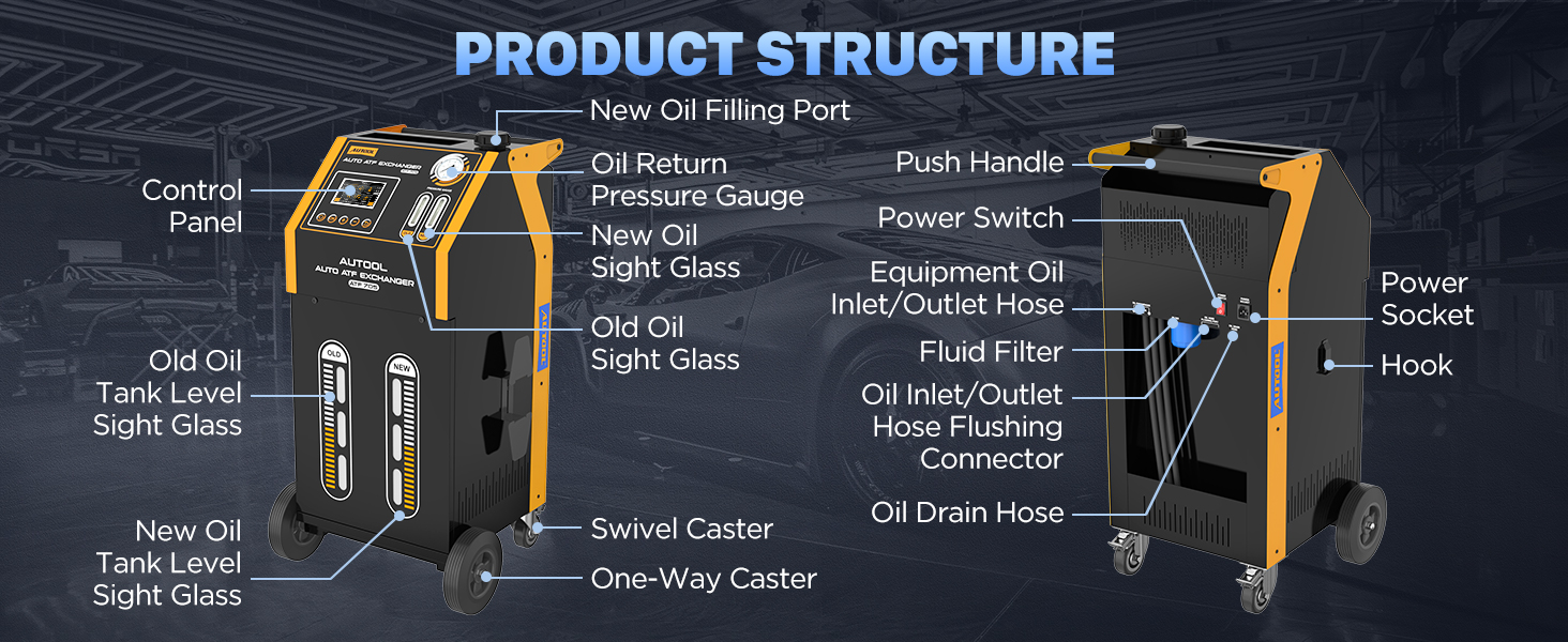
Identify your ATF705 revision before setup
Current AC-layout units have a rear power socket and switch, a five-inch screen, one mechanical pressure gauge, new and used fluid windows, tank-level windows, exchange hoses, a drain hose, filter, and hose-flushing connector. Confirm whether your regional nameplate calls for 110 V or 220 V; the connector shape alone is not a voltage test.
Legacy ATF705 units use a DC 12 V lead with battery clamps and an older screen flow. On those machines, follow the clamp markings and the matched manual. Do not connect a legacy 12 V unit to mains, do not power an AC unit from battery clamps, and do not improvise an adapter between them.
The delivered screen wording controls. If your menu differs from this guide, stop and use its matching manual instead of assuming that a similarly positioned icon performs the same function.
ATF705 step-by-step operating procedure
Step 1: Confirm that exchange is appropriate
Record the driver’s concern, service history, previous fluid, leaks, warning lamps, shift quality, and any additives. Scan the transmission and related modules. Inspect accessible fluid, pan evidence, cooler lines, connectors, and external leakage.
Diagnose severe slipping, delayed engagement, loss of drive, burnt fluid with heavy debris, coolant contamination, hydraulic faults, and active electrical or mechanical codes before connecting an exchanger. Establish a baseline for codes, temperature, and operation.
Completion check: The transmission is a suitable maintenance candidate and no fault must be repaired or inspected first.
Step 2: Define the exact fluid and finish procedure
Use vehicle identification, transmission code, build data, and current manufacturer information to choose the exact ATF. Never choose by color or a broad “multi-vehicle” statement alone.
Record the planned exchange quantity, target level-temperature window, engine and selector state, dipstick or overflow method, required scan data, fill hardware, torque, adaptation, and road-test criteria. Leave contingency fluid for priming and final adjustment without exceeding the machine’s safe capacity.
Completion check: The job card contains one verified ATF specification and the complete vehicle-specific level method.
Step 3: Confirm hardware, software, and power revision
Photograph the ATF705 nameplate and note serial or revision information. Match the physical power inlet, rated voltage, current menu, fill/drain plumbing, and supplied manual. Inspect the correct power cable or DC clamp lead from end to end.
For an AC-layout unit, verify the regional supply, grounding, cable rating, and outlet protection. For a legacy DC unit, verify a suitable 12 V source and the delivered clamp markings. Keep power disconnected during fluid-path setup.
Stop: Any mismatch among nameplate, plug, manual, or menu must be resolved before use.
Completion check: The machine revision and its single approved power method are positively identified.
Step 4: Inspect, empty, and zero the machine correctly
Inspect exchange hoses, drain hose, filter, fittings, seals, screen, buttons, pressure gauge, tank windows, cable, switches, wheels, and cabinet. Both internal tanks must sit correctly on their scale platforms, and the cabinet must be level.
Drain used fluid before it reaches capacity. Remove incompatible new fluid to a clean labelled container rather than using the customer’s transmission to purge the machine. The manual permits one-key scale zeroing only after both tanks are empty. Never zero a loaded tank; that destroys the reference used for equal exchange.
Completion check: The paths are clean and segregated, tanks have capacity, scale readings are plausible, and zeroing—if required—was performed empty.
Step 5: Load the exact new ATF
With power off, clean the fill area and add the planned exact-specification ATF using dedicated equipment. Prevent water, dirt, lint, old fluid, cleaner, and mixed ATF from entering the new tank.
Confirm the screen and physical level indication change plausibly. Do not exceed the tank limit, and do not begin a programmed exchange with less new fluid than the selected quantity plus the required reserve.
Common mistake: Planning to top up the machine mid-exchange. The manual prohibits adding new ATF while equal exchange is running because the scale reference and balance can be upset. Stop and finish the function before adding fluid.
Completion check: The correct fluid is loaded, identified, within capacity, and sufficient for the selected program.
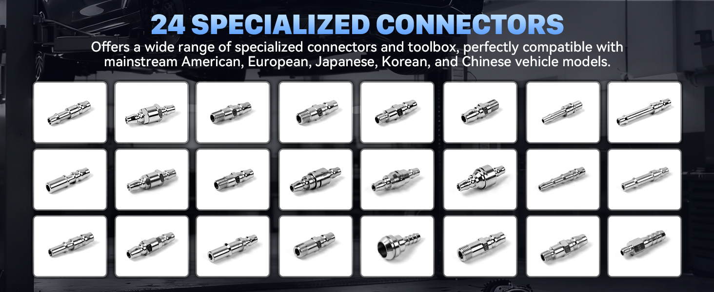
Step 6: Select adapters and open the approved connection
Use the vehicle procedure to locate a serviceable point in the transmission cooler circuit. Let the system reach its specified safe condition, clean the area, provide containment, and release pressure as instructed before opening it.
Match adapters by thread, flare, seal, diameter, insertion depth, locking method, and flow area. Inspect O-rings and sealing faces. Never force a fitting, omit a retainer, stack improvised parts, or reduce the circuit with an undersized passage.
Cap open ends and retain or replace vehicle seals and clips exactly as required.
Completion check: Both vehicle ends and both machine fittings lock securely, seal, and preserve flow without side load.
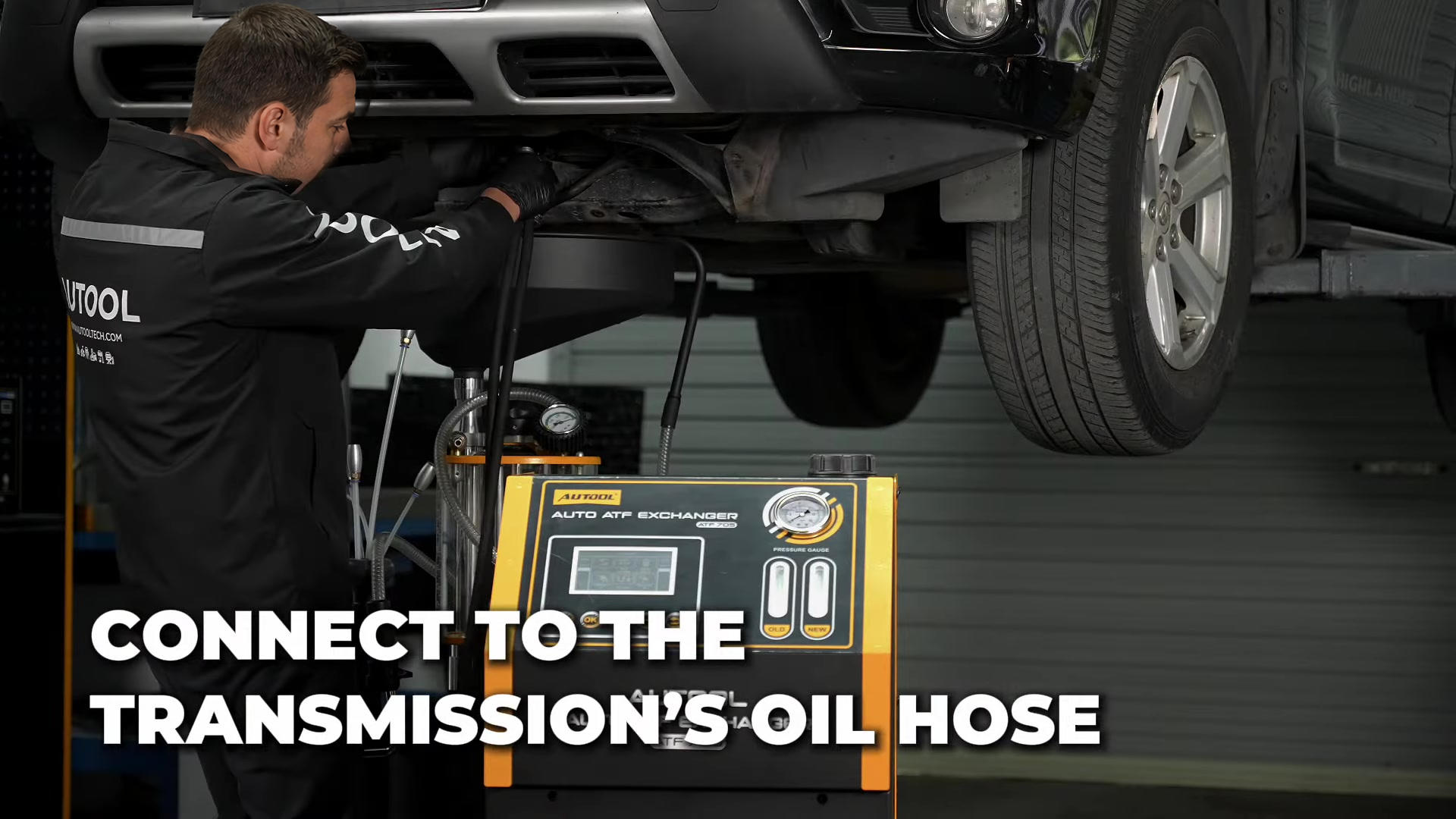
Step 7: Build and inspect the closed circuit
Connect the two ATF705 exchange hoses to the separated vehicle circuit. Current ATF705 software can recognize inlet and outlet direction, so the hoses may be connected without manually assigning direction when the matching manual permits it. That feature does not excuse an incomplete connector or unsafe route.
Pull-test each lock. Support hoses with broad bends and enough slack for engine movement. Keep them clear of heat, fans, belts, shafts, wheels, lift hardware, and sharp edges. Verify that the drain hose is closed and secured.
Completion check: The circuit is closed, both fittings are retained, hoses are protected, and the drain path cannot open accidentally.
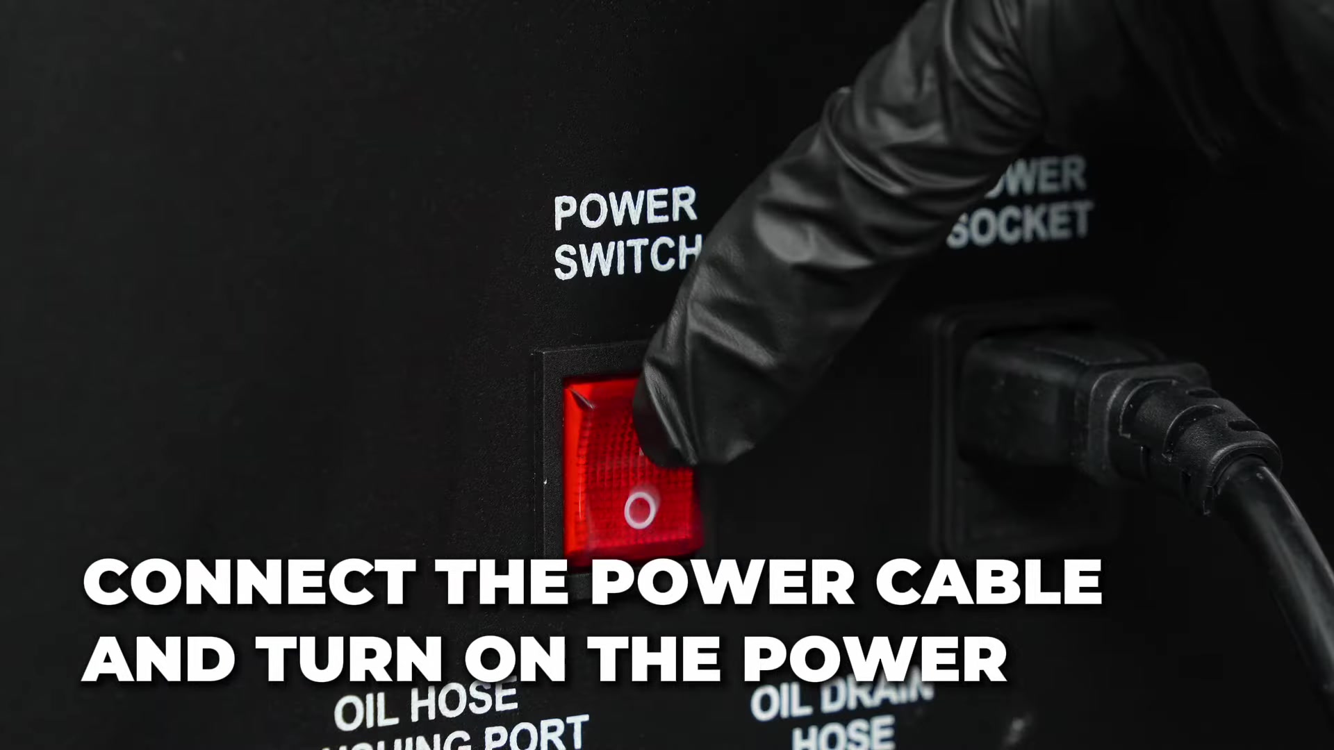
Step 8: Apply only the nameplate-matched power
On a current AC-layout machine, leave its switch off, connect the matched power cable fully, then energize only a grounded supply at the exact nameplate voltage. Do not use an extension or voltage converter unless it is specifically rated and approved for the machine and workshop.
On a legacy DC 12 V machine, keep the device off, follow the delivered red/black clamp markings, connect only to a suitable 12 V system, and route the lead away from vehicle movement. Do not infer polarity behavior from another revision.
Power on and confirm that the screen starts normally, the tank values are plausible, and no fault appears.
Completion check: Exactly one approved power method is in use and startup data passes a plausibility check.
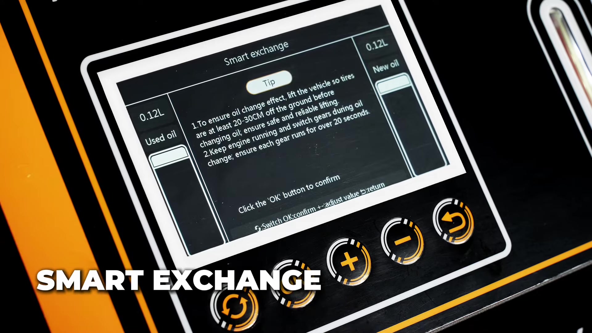
Step 9: Choose the correct screen function and quantity
Use Smart Exchange or Equal Exchange only when its on-screen description matches the planned job and the delivered manual. Current Smart Exchange displays new/used quantities while managing the process; Equal Exchange allows a selected quantity. Do not assume those names have identical logic on every software revision.
Enter the vehicle-approved planned quantity, never a generic capacity or an automatic extra amount. Confirm the new-tank reading is at least the selected quantity and the used tank has more than enough free capacity. Read every prompt before pressing OK or Start.
Completion check: The selected function, quantity, tank values, and vehicle plan agree before the engine or machine begins exchange.
Step 10: Let the machine identify flow and prove leak-free operation
Operate the vehicle only in the state specified by its service procedure. Keep the brake applied and driven wheels stationary unless an explicit manufacturer procedure requires controlled rotation on suitable equipment.
Allow the ATF705 to identify flow direction. Watch the pressure gauge, physical fluid windows, tank values, hoses, adapters, and underside of the vehicle. Confirm that used fluid moves to the used side and new fluid is available without air.
Stop: Shut down for a direction-recognition fault, no flow, reversed screen behavior, leakage, hose movement, aeration, abrupt pressure change, unstable vehicle, or unexpected tank movement.
Completion check: Direction recognition completes, the circuit remains dry, and all readings behave consistently.
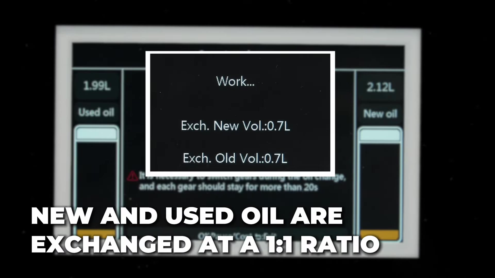
Step 11: Run the supervised equal-volume exchange
Start the selected program and remain at the machine. The screen may control delivery and recovery, but continuously compare its new/used quantities with physical windows and tank levels. Watch pressure, flow continuity, connections, hose routing, and vehicle behavior.
Follow only the vehicle-approved gear sequence and dwell. Do not reproduce a generic speed or lift-wheel instruction. If driven-wheel operation is explicitly required, use trained personnel and a lift or dynamometer rated for that condition, with exclusion zones and all vehicle-maker controls.
Never add ATF to the machine mid-program. Do not bypass a warning, increase speed to force flow, or leave the machine unattended.
Completion check: The exchange remains balanced and stable, the selected quantity advances normally, and no safety, pressure, tank, fluid, or vehicle limit is approached.
Step 12: Respond to prompts and stop by controlled gates
Read each gear, progress, low-fluid, tank, or completion prompt in context. A completion screen means the selected machine program ended; it does not prove final vehicle level or a repaired transmission.
Stop before the new supply runs low, the used tank fills, air enters either path, the planned quantity is exceeded, or an abnormality develops. Do not chase perfectly clear return fluid or a marketing percentage with unlimited ATF.
When the planned exchange ends, follow the screen’s stop sequence, then shut down the vehicle and isolate power as required before touching a fluid connector.
Completion check: The planned quantity completed without imbalance, overflow, air, leakage, abnormal pressure, or ignored warning.
Step 13: Restore the vehicle cooler circuit
Allow pressure and temperature to reach the vehicle’s service condition. Place containment below the connection, release machine fittings carefully, and cap the machine hoses. Restore the original cooler path with specified new seals, clips, retainers, and torque.
Clean spilled ATF from the case, lines, undertray, exhaust area, and nearby parts. Verify that no temporary cap, plug, adapter, or tool remains and that no hose or wiring was displaced.
Completion check: The original circuit is fully retained and torqued, and the area is clean enough for a reliable leak check.
Step 14: Set final level and verify the vehicle
Use the exact transmission temperature, engine state, selector position, and dipstick or overflow procedure. An equal-volume screen cannot replace this step. Add or drain only the correct ATF, renew the level-plug seal when specified, and torque the hardware.
Inspect the cooler circuit, level point, pan, and disturbed parts under the required static and running states. Confirm normal selector engagement and scan data. Perform adaptation only when specified. Road-test only after level, retention, underbody clearance, and leak checks pass, using the manufacturer’s drive cycle rather than a fixed distance.
Record machine revision, power type, ATF specification and batch, selected and actual quantities, final level temperature, adjustment, codes, adaptation, and leak-check result.
Completion check: Level, sealing, operation, diagnostics, and documentation all pass.
Cycle cleaning is optional
Do not add a cleaner or run a flush by default. Chemical cleaning requires written approval from the transmission manufacturer, chemical supplier, and instructions for the delivered ATF705 revision. If any one is missing, perform only the approved fluid exchange.
When circulation is authorized, use the delivered Cycle Cleaning function and exact introduction method. The amount, time, temperature, selector sequence, and subsequent exchange quantity come from the approved procedures. Ignore generic time, extra-fluid, or high-speed examples that conflict with the vehicle plan.
Maintain the same leak, hose, wheel, pressure, tank, power, and supervision controls. Stop for foam, air, leakage, pressure anomalies, shift faults, warning messages, or unusual noise.
Use the utility functions deliberately
Add New Oil
Use this only when the vehicle procedure calls for a measured addition and the delivered menu confirms the connection state. The legacy manual says not to start the engine during this function. Set no more than the verified new-tank amount, then finish with the vehicle-specific level procedure.
Recycle Used Oil
Use this only when recovering a measured quantity from a correctly connected vehicle is part of the service plan. Confirm free waste capacity and the engine/selector state required by the matched manual and vehicle procedure.
Line Clean or Pipe Self-Clean
This cleans the machine’s fluid path after the vehicle has been disconnected and the exchange hose is attached to the labelled flushing connector on current units. Confirm the screen diagram and physical port before starting. Never connect the wrong hose or discharge to an open floor container.
Drain New Oil
Use only with machine hoses disconnected from the vehicle, as the delivered instructions require. Transfer clean compatible fluid to a dedicated labelled container or manage contaminated fluid as waste.
Drain Used Oil
Connect the drain path to a compatible waste container with enough capacity, open only the indicated manual valve when prompted, and supervise the entire transfer. Close the valve, cap the hose, and manage waste ATF under local rules.
Three completion gates
| Gate | Evidence required |
|---|---|
| Machine | Correct revision and power, plausible scales, planned quantity, stable equal exchange, no warning, air, pressure anomaly, leak, or tank overrun |
| Vehicle circuit | Correct adapters removed, original cooler path restored with specified seals, retention and torque, no static or running leak |
| Transmission | Exact ATF, temperature-correct final level, normal engagement and scan status, required adaptation and post-drive checks complete |
The screen’s “completed” message passes only the machine program gate. The job is not complete until all three gates pass.
Common problems and corrections
The screen or power inlet does not match this guide
Stop. Identify the machine’s nameplate and obtain the matching manual. Do not translate an icon from another revision or try both power methods.
Direction recognition does not complete
Stop the vehicle and machine. Check the approved operating state, fluid level, adapter engagement, kinks, closed drain valve, blocked filter or cooler, and actual flow. Do not rev the engine to force recognition.
New and used quantities separate unexpectedly
Stop before the transmission level moves outside control. Check scale loading, cabinet level, mid-process fluid addition, tank contact, air entry, leakage, line restriction, and incorrect function selection. Empty both tanks before any approved zeroing.
Flow pulses or bubbles appear
Stop before air enters the transmission. Check new-fluid supply, tank pickup, fittings, filter, fluid compatibility, and leaks. Correct the cause and reprime only as the matched revision directs.
Pressure changes sharply
Stop and inspect for a kink, wrong adapter, blocked cooler, closed path, incorrect vehicle state, cold/high-viscosity fluid, or connection fault. The gauge indicates a condition; it does not supply one universal target.
Scale care, maintenance, and storage
After each job, drain used ATF promptly and store reusable new ATF in a clean labelled container. The exact manual requires both machine tanks empty during storage so the scales remain unloaded. Keep the new side uncontaminated.
Inspect hoses, seals, filter, drain valve, fittings, gauge, screen, buttons, power cable or clamp lead, inlet, fuse, casters, fasteners, and cabinet. Replace damaged or aged parts before use. Keep fluid away from electrical connections and treat corrosion without contaminating the fluid path.
If empty tanks do not read correctly, place the cabinet level and use the delivered one-key zero function only with both tanks empty. If the error remains, stop and have the scales calibrated; do not compensate by entering a false exchange quantity.
Store the ATF705 upright in a dry, ventilated place away from heat, moisture, weather, and ignition sources, with power disconnected and hoses capped.
ATF705 FAQ
Is every ATF705 powered the same way?
No. Current materials show regional AC 110/220 V units, while earlier exact-model units use DC 12 V clamps. The delivered nameplate and matching manual control.
Does automatic flow recognition remove the need to check connections?
No. It identifies direction after a correct closed circuit exists. You still must match, lock, route, and leak-check every fitting.
What is the difference between Smart Exchange and Equal Exchange?
On the current screen, Smart Exchange visibly tracks new and used movement while managing the process, and Equal Exchange accepts a selected quantity. Software revisions can differ, so use the delivered on-screen description and manual rather than assuming identical logic.
Can I add new ATF while exchange is running?
No. The exact instructions prohibit mid-process addition during equal exchange because it can upset the measured balance. Stop and finish the function first.
Must I lift the drive wheels and run them at speed?
No universal instruction is safe. Default to stationary wheels. Use driven-wheel operation only when the exact vehicle procedure requires it and controlled equipment, trained staff, and exclusion zones are in place.
Is a “completed” screen the end of the job?
No. Restore the cooler circuit, set final level at the specified temperature and state, inspect for leaks, verify operation and scan status, and complete any required adaptation or post-drive check.
The reliable ATF705 workflow
First match the hardware, software, and power revision. Then verify the transmission is a suitable candidate, define the exact ATF and final-level method, inspect and empty the machine, load clean fluid, choose correct adapters, build a protected closed circuit, and apply only nameplate-matched power.
Select the correct screen function and planned quantity, prove automatic flow recognition and leak-free operation, supervise equal-volume exchange, and stop by tank, quantity, pressure, air, and vehicle gates. Restore the cooler circuit, set level at the exact temperature, verify the vehicle, drain and clean the machine, and store both tanks empty.











Comments 0
Questions, fixes, and real-world diagnostic notes from readers.
Be the first to share a diagnostic result or ask a follow-up question.