
How to Choose and Use AUTOOL 48-, 68- and 92-Piece Automotive Test Lead Kits

Automotive test leads let you reach a terminal without turning the wiring harness into the test point. The useful question is not simply whether a kit contains 48, 68 or 92 pieces; it is whether the case contains the terminal shapes, probes, extensions and clips needed for the circuits you service—and whether every component is suitable for the planned measurement. This guide shows how to select among the three current AUTOOL kits and use a lead chain without cutting wires or spreading connector terminals.
Quick answer: Start with the vehicle wiring diagram and the measurement you need. Choose the smallest kit that covers the connector families you actually encounter, inventory every lead before use, and treat the meter, leads, adapters and circuit as one rated system governed by its weakest component. Back-probe only where the service procedure allows it, keep test tips from bridging adjacent pins, use the correct meter socket and function, capture the expected value and actual value, then power down and restore seals, locks and connector tension.
In this guide
Choose 48, 68 or 92 pieces by connector coverage
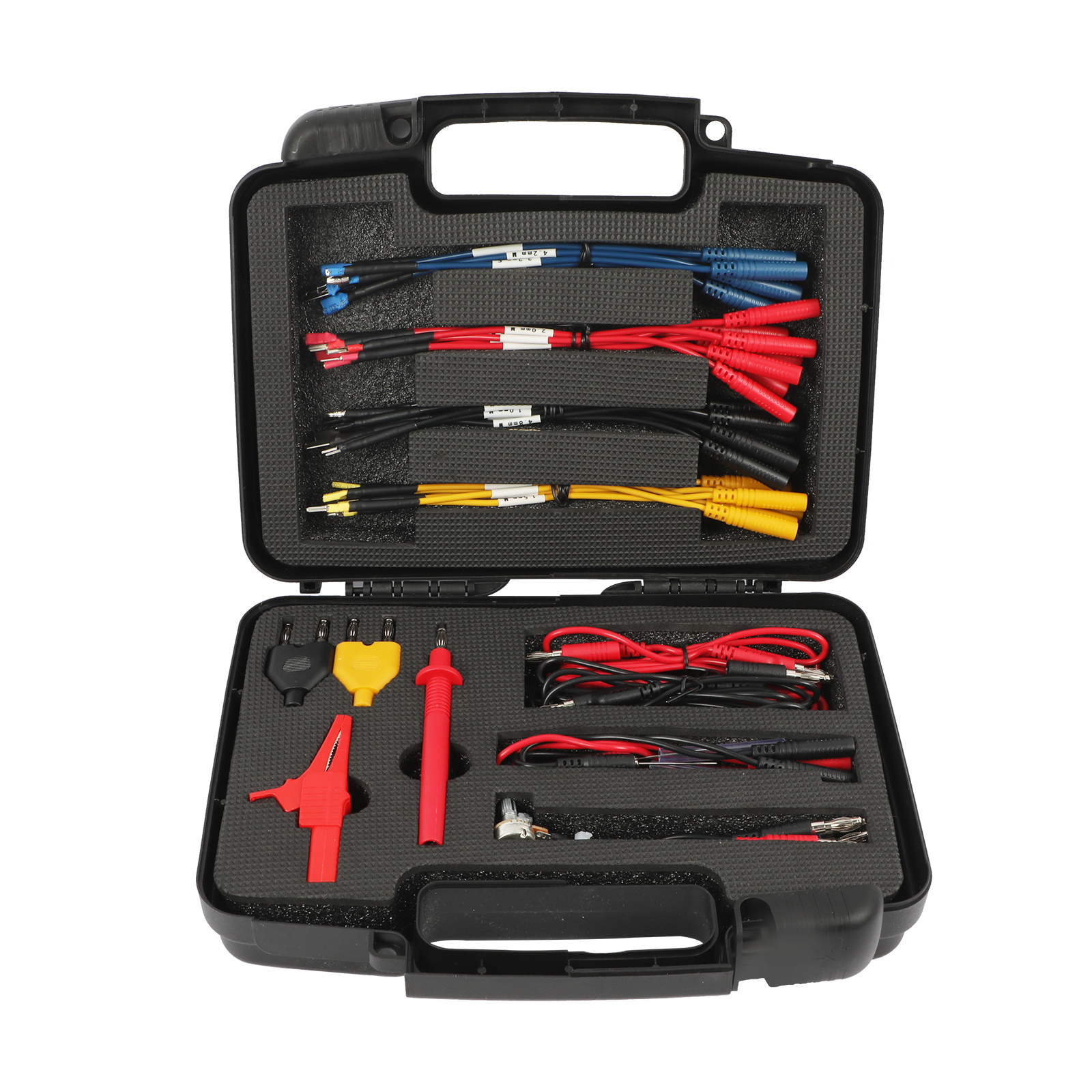
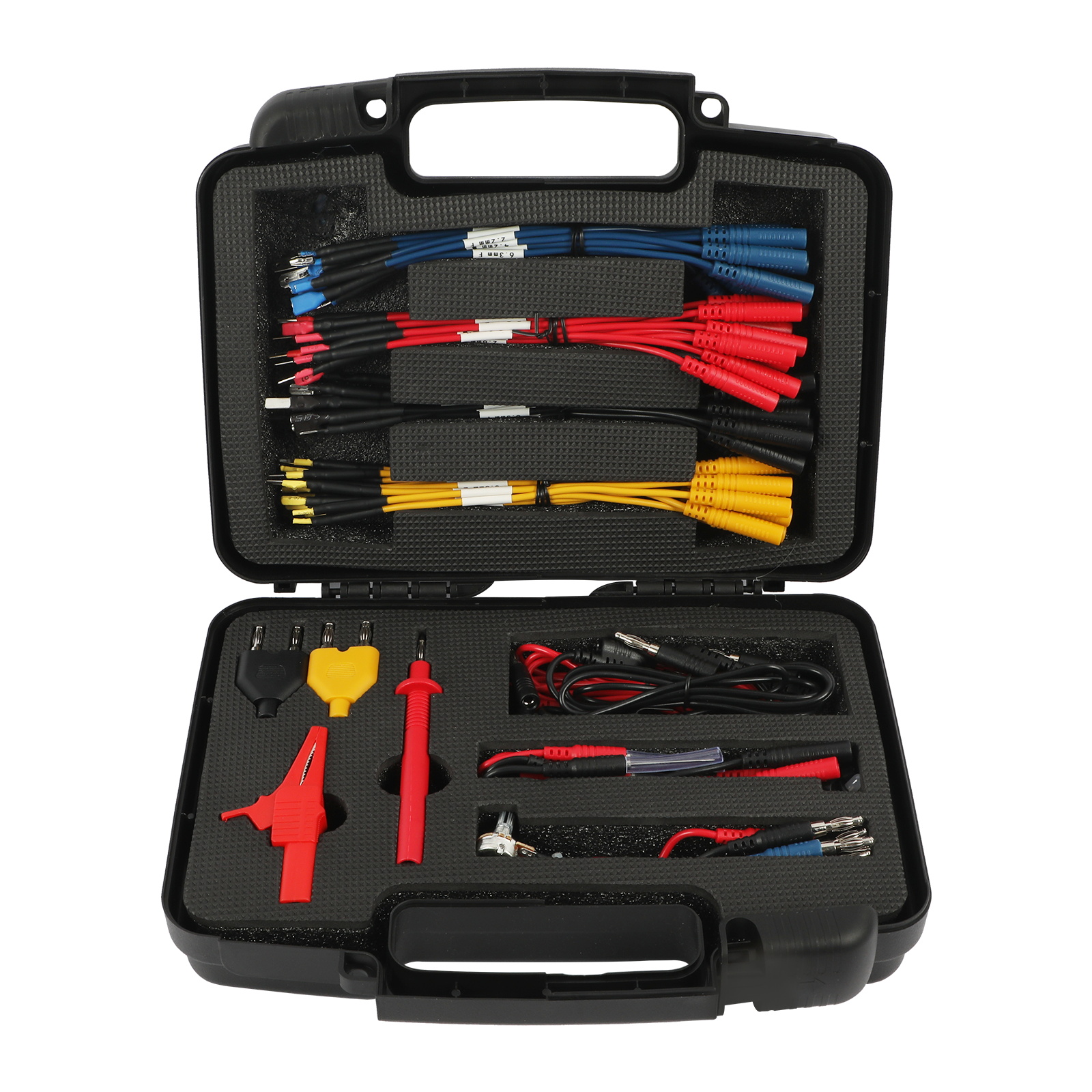
All three current sets are presented for automotive circuit work and organized in carrying cases. The 48- and 68-piece pages describe probes, banana adapters, extension leads, clips, signal or potentiometer-style leads and color-coded terminal jumpers; the 92-piece set expands the terminal-lead groups and accessory coverage. Those descriptions help identify what is in the case, but they do not replace an exact inventory or establish that every piece has the same electrical rating.
| Current kit | Best selection logic | Final check |
|---|---|---|
| AUTOOL 48-piece kit | A compact starting set for common back-probing, meter extension, clips and several color-coded terminal jumper groups. Choose it when its exact packing list covers the connector families in your workload. | Match the current packing list to your terminals and instruments. |
| AUTOOL 68-piece kit | Adds broader probe, adapter and jumper-wire coverage while retaining the organized case format. Compare the exact terminal groups with the 48-piece list rather than assuming the extra count solves every connector. | Match the current packing list to your terminals and instruments. |
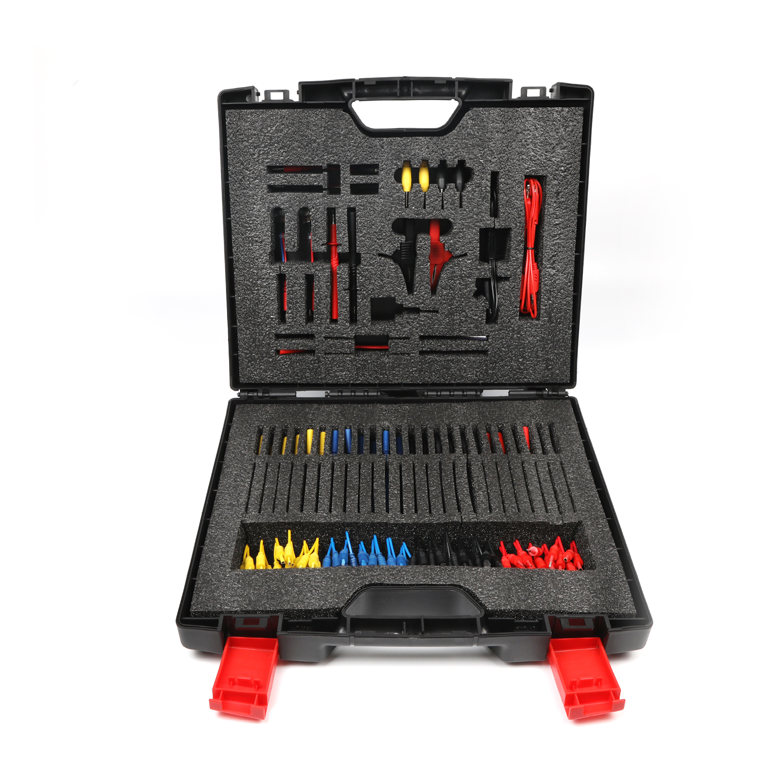
| AUTOOL 92-piece kit | The broadest current case, with multiple terminal-lead groups and a wider organized layout shown in the official video. Choose it for repeat workshop use only when you will identify and maintain the extra adapters. | Match the current packing list to your terminals and instruments. |
More pieces are useful only when they are identifiable. A case full of unlabeled jumpers makes it easier to select a terminal that is merely close in size, which can spread or deform the vehicle connector. Keep the molded case layout, create an internal position map if necessary, and replace missing pairs deliberately. Do not mix anonymous leads from another kit unless their dimensions, construction and ratings are known.
Know what each lead can—and cannot—do
- Terminal jumper: mates with a compatible connector terminal so the circuit can remain assembled through a controlled breakout. It must match blade width, thickness, contact style and gender without force.
- Back-probe: reaches the conductor side of a connected terminal only when the connector design and service procedure allow it. It should not pierce seals, enlarge cavities or push the terminal forward.
- Banana adapter or extension: links the selected automotive lead to a compatible meter or oscilloscope input. A 4 mm plug shape alone does not prove rating or instrument compatibility.
- Alligator clip: provides a stable temporary connection on an approved exposed point. Keep the jaws from touching adjacent conductors or moving parts.
- LED or variable/potentiometer-style lead: is a specialized accessory, not a universal signal generator. Use it only when the exact circuit procedure defines the connection and permitted electrical behavior.
A marking on one clip—such as the 32 A / 1000 V wording shown on current 48- and 68-piece product pages—describes that named component, not the complete assembled chain and not a blanket permission to test a 1000 V system. The meter input, fuse, probe, adapter, jumper, insulation, connector environment and circuit category all matter. These general automotive kits should not be treated as high-voltage EV, hybrid traction-battery or mains test equipment.
Before touching the circuit: Confirm the expected voltage or signal, meter function, input sockets, circuit energy, ground reference and whether the circuit must be powered, loaded or disconnected. If the circuit is part of an airbag, pyrotechnic device, high-voltage system, safety controller or another manufacturer-restricted system, stop and use the specified procedure and approved equipment.
How to use an automotive test lead kit
Step 1: Define one electrical question
Write the symptom and the single value needed next: supply voltage under load, ground voltage drop, signal level, resistance with power removed, continuity of an isolated conductor, or current through a specifically opened path. Copy the expected condition from reliable service information, including key position, connector state, load and reference point. Avoid broad instructions such as “check the wiring,” because they encourage random probing and make the result hard to interpret.
Check: The worksheet contains one circuit, one expected value, one operating condition and two named test points.
Step 2: Choose the meter function and input sockets
Inspect the instrument, leads and internal fuse status. For voltage or resistance, place the common lead in COM and the measurement lead in the input specified by the meter. Current measurement normally requires opening the circuit and using a current-rated input and fuse; never move the lead into a current jack merely to look for voltage. Set a safe range or verified auto-range before connecting to the vehicle.
Check: The selected function, range and sockets match the planned measurement, and the meter is suitable for the circuit.
Step 3: Select the exact terminal lead
Compare a candidate adapter with an approved mating terminal or the dimensions in the service procedure. Match blade width, thickness, contact orientation and male/female form. Do not test-fit multiple sizes in the vehicle connector. The official 92-piece demonstration shows the color groups stored separately; color is an organization aid, not proof that a lead matches a particular vehicle terminal.
Check: The selected lead mates without force and its identity is recorded before the case is closed.

Step 4: Inspect the complete measurement chain
Check the meter leads, banana plugs, extension, automotive adapter, probe and clips for cuts, heat damage, corrosion, loose boots, exposed conductor or bent tips. Verify that shrouds and insulation remain intact and that the assembled chain does not expose more metal than the test point requires. Replace a suspect part instead of holding it at an angle to maintain contact.
Check: Every component is clean, intact, known and suitable for the planned circuit.
Step 5: Make the circuit safe for connection
Secure the vehicle, keep jewelry and loose clothing away from moving parts, and arrange the meter where it cannot fall into belts or fans. For resistance or continuity, de-energize and isolate the circuit as directed and allow stored energy to discharge. For a powered voltage or signal test, make the physical connections in the state specified by service information before switching to the required operating condition.
Check: The circuit is in the documented connection state and the workspace controls accidental shorts and movement.
Step 6: Connect without cutting, piercing or spreading terminals
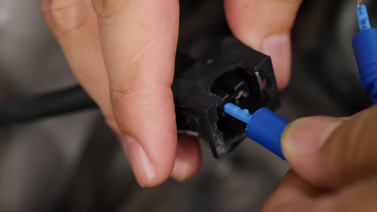
Back-probe from the wire side only when allowed, following the existing wire path without puncturing insulation or damaging a seal. For an in-line breakout, connect the correct male and female terminal leads to preserve the circuit path. Hold insulated housings rather than bare metal. The official demonstration shows a selected lead inserted into a matching connector shell; it does not authorize forcing the same lead into every connector.
Check: The terminal remains locked, sealed and mechanically unchanged, with no adjacent pins bridged.
Step 7: Establish a stable reference connection
Attach the common lead to the exact ground or reference point required for the test. An easy-to-reach body bolt is not automatically the correct reference for a sensor or voltage-drop measurement. Use an insulated clip where appropriate so both hands can remain clear of moving components, and route the lead so vibration cannot move the jaws into another conductor.
Check: The reference point is electrically correct, mechanically secure and clear of moving or hot parts.
Step 8: Power the circuit and read under the specified condition
Move the ignition, load or actuator only to the documented state. Observe the measurement without changing probe pressure or moving the harness unless the procedure calls for a controlled wiggle test. Record units, polarity, range, operating condition and whether the value is steady or intermittent. A screenshot or note should show enough context to distinguish 0.05 V from 0.05 A or 0.05 kΩ.
Check: The actual value is captured with units and conditions and can be compared directly with the expected value.
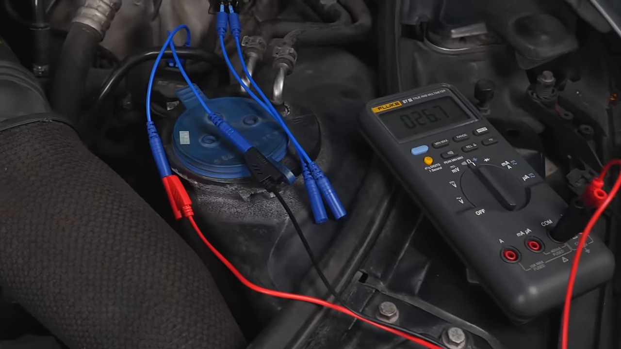
Step 9: Validate an implausible result before diagnosing a part
If the value is impossible, first recheck meter function, jack selection, range, reference point, terminal contact and lead continuity. Use a known source or lead self-check appropriate to the instrument. Then repeat the test without changing several variables at once. A perfect zero, overload indication or reversed polarity may describe the setup rather than the vehicle fault.
Check: The test chain has been verified independently enough that the result can support the next diagnostic decision.
Step 10: Power down, disconnect and restore the connector
Return the circuit to the specified safe state. Remove clips and probes by their insulated housings, then separate breakout leads without pulling wires. Inspect the vehicle terminals for spreading or push-back, confirm seals and secondary locks are correctly seated, refit covers and erase temporary lead labels only after the result is recorded. Clean and return every adapter to its case position.
Check: The original harness is intact, locked and sealed; no test lead or exposed terminal remains in the vehicle.
What to check when a measurement makes no sense
Treat the test setup as a circuit of its own. A high-resistance adapter, wrong reference point, current-jack mistake or terminal that only touches when pushed can create a believable but false result. Restore the last known-good arrangement and work from the instrument toward the vehicle one connection at a time.
- Confirm the display unit, multiplier and sign, then confirm the rotary function and input sockets.
- Short the meter leads only when the meter procedure permits it and record their resistance before a low-resistance test.
- Check the selected automotive adapter against a known mating terminal; do not improve contact by forcing a larger blade.
- Repeat the measurement at a verified reference point and compare loaded and unloaded conditions only when the diagnostic plan calls for both.
- If moving the lead changes the value, remove the lead from service until the intermittent connector, conductor or strain relief is identified.
Stop: Stop immediately if a lead, adapter or meter becomes warm; insulation softens; a fuse opens; arcing occurs; a control unit behaves unexpectedly; a probe can bridge adjacent pins; or the circuit voltage, current or energy is outside the verified capability of every component. Do not bypass a fuse, hold a loose terminal by hand or substitute an unrated lead.
Frequently asked questions
Is the 92-piece kit automatically better than the 48-piece kit?
No. The better kit is the one whose exact terminal and accessory inventory matches your workload and can be kept identified. More pieces add coverage only when you know which lead fits, how it is rated and where it belongs after use.
Can I choose an automotive terminal lead by color?
No. Color helps organize groups, but it does not prove blade dimensions, contact style, gender, pin assignment or electrical suitability. Match the actual terminal and the service procedure.
Can these leads be used on high-voltage EV or hybrid systems?
Do not assume so. General 12 V and 24 V automotive accessory descriptions and a marking on one clip do not qualify the complete kit for a traction-battery or other high-energy system. Use the vehicle manufacturer’s procedure, trained personnel and equipment specifically rated for that work.
Should I pierce wire insulation if I cannot reach the terminal?
Avoid it unless the manufacturer’s exact procedure specifically permits a piercing method and defines how to seal the wire afterward. Prefer an approved back-probe or breakout connection that preserves insulation, seals and terminal tension.
Why does resistance change when I move the probe?
The contact may be unstable, the terminal may be mismatched, or the lead may have an intermittent conductor or strain relief. Stop interpreting the vehicle circuit until the measurement chain gives a stable known-source or self-check result.
Final test-lead checklist
- One circuit question, expected value, condition and test points are defined
- Meter function, range, input sockets, fuses and circuit rating are verified
- Selected terminal adapter matches by dimensions and contact form—not color alone
- Every lead, clip, probe and extension is clean, intact and identified
- Connection method preserves wire insulation, seals, locks and terminal tension
- Reference point, route and working area are mechanically safe
- Actual value is recorded with units, polarity and operating condition
- Result is validated before a component is condemned
- Circuit powers down and the original connector is inspected and restored
- Every adapter returns to its labeled case position
A good test-lead kit reduces damage only when selection and measurement discipline remain stronger than convenience. Choose coverage you can identify, build the shortest suitable measurement chain, verify the instrument before touching the circuit, and leave the connector exactly as you found it.











Comments 0
Questions, fixes, and real-world diagnostic notes from readers.
Be the first to share a diagnostic result or ask a follow-up question.