
How to Install and Use the MRCARTOOL M85 GPS Inclinometer

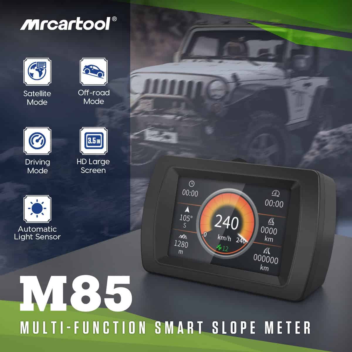
The MRCARTOOL M85 GPS inclinometer is a satellite-based dashboard display for speed, direction, position, trip information, voltage, pitch and roll. It does not need an OBD data connection: the official demonstration powers it from a vehicle accessory socket, then cycles through Driving, Satellite, Off-road and Slope Meter displays. A useful installation depends on three separate checks—safe power, a stable GPS fix and a level angle reference.
Quick answer: Park on verified level ground, choose a rigid dashboard position that does not block the road, instruments, airbags or vents, and dry-fit the M85 square with the vehicle centerline. Use the supplied car-charger cable for a reversible installation; have a qualified installer handle the included ACC retrofit lead. Route the cable away from controls, connect the rear mini-USB plug and power the unit. Wait outdoors until satellite time, direction, position and speed behave plausibly. With the vehicle still level and stationary, use the exact M85 control indicated in its printed instructions to set the slope reference to zero. Cycle through all four displays while parked, adjust only settings you understand, then verify the installation on a short controlled drive.
In this guide
Understand the M85 before installation
M85 is a GPS inclinometer rather than an ECU scanner. Its exact product page lists altitude, satellite time, travel speed, driving time, compass direction, current and total distance, latitude and longitude, satellite count, pitch, roll, automatic brightness and a fatigue warning. The page also mentions voltage and current, but the official interface material clearly labels voltage only; treat displayed voltage as an accessory-circuit trend and do not claim that the unit measures battery current.
The specified electrical range is DC 5–35 V, working current is below 80 mA, sleep current is below 10 mA and operating temperature is -20°C to 75°C. Those ratings describe the device, not permission to connect to any convenient wire. The vehicle circuit, fuse, grounding, polarity and accessory-socket rules still control. The page lists a car-charger cable and an ACC retrofit lead, so decide between reversible and fixed power before routing anything.
Complete setup only while parked. Keep the screen below the normal road view, keep its cable away from pedals and steering, and keep both outside every airbag deployment zone. Pitch and roll numbers, alarms and GPS speed are supplementary information. They cannot determine traction, rollover margin, safe terrain, legal speed or whether a route is passable.
Mount and power the M85
1. Choose a level reference and viewing position
Set normal tire pressures, normal ride height and the usual load before creating an angle baseline. Park on a surface known to be level in both directions; a visually flat driveway can still have drainage slope. Place the M85 low on a rigid portion of the dashboard and sit in the normal driving position. Confirm that the housing does not hide warning lamps, gauges, the hood line, pedestrians or nearby road surface. Leave clearance around its automatic-light sensor.
2. Dry-fit the base square with the vehicle
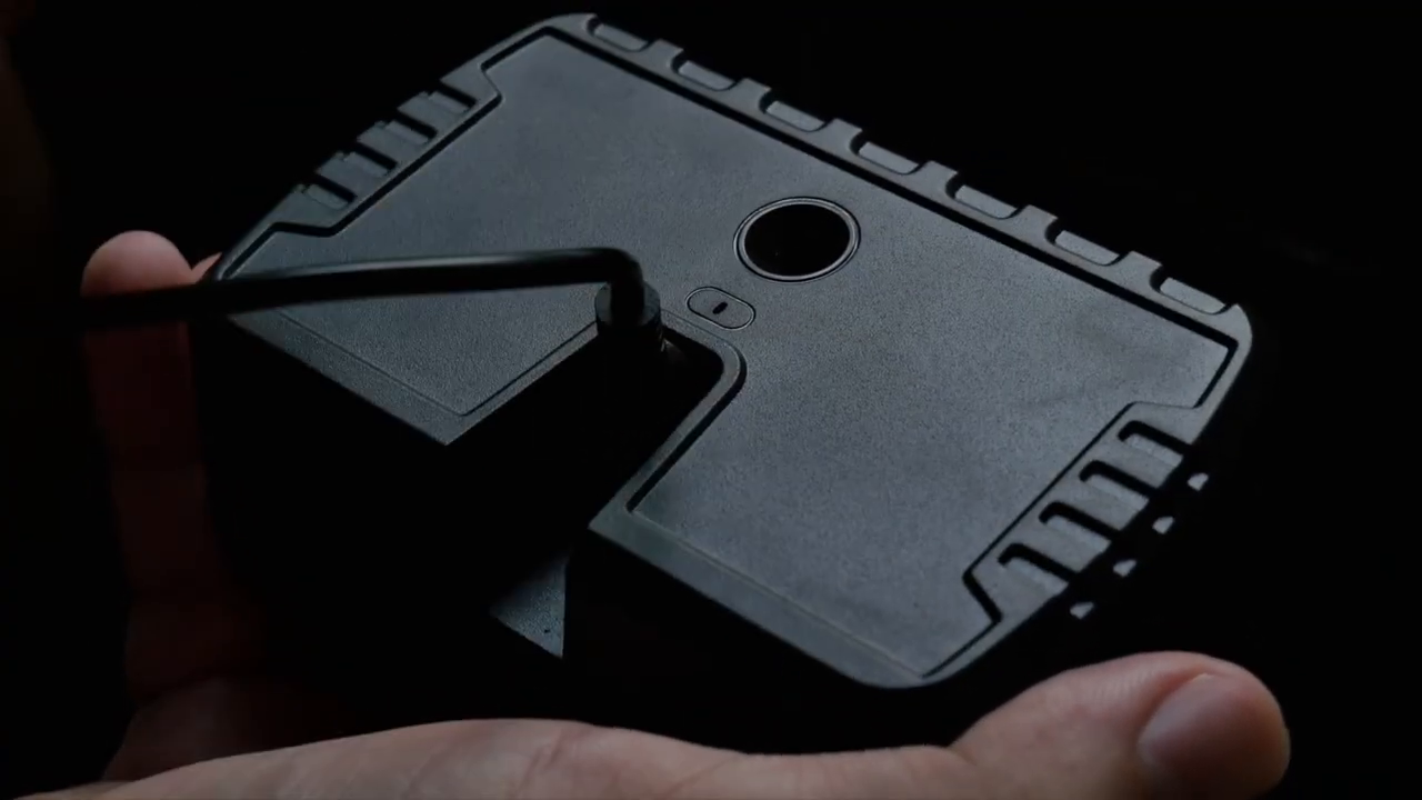
The product page instructs the user to attach double-sided tape to the base and select a suitable dashboard position. Before removing the liner, align the display face perpendicular to the vehicle centerline. A case rotated left or right mixes vehicle pitch into the roll indication. Press on the proposed surface to confirm it does not flex, then check that the rear mini-USB cable can leave without a sharp bend. Clean the surface with a material-safe method and let it dry before applying the tape.
3. Choose the supplied power method
For the simplest installation, keep the ignition off, insert the supplied car charger into the vehicle accessory socket, connect the rear mini-USB plug and secure excess cable. The official M85 video shows this exact sequence. Do not pull the cable tight across a console, leave a loop near a gear selector or route it over an airbag seam. If the socket stays live after key-off, unplug the unit when parked until actual sleep and battery behavior have been verified.
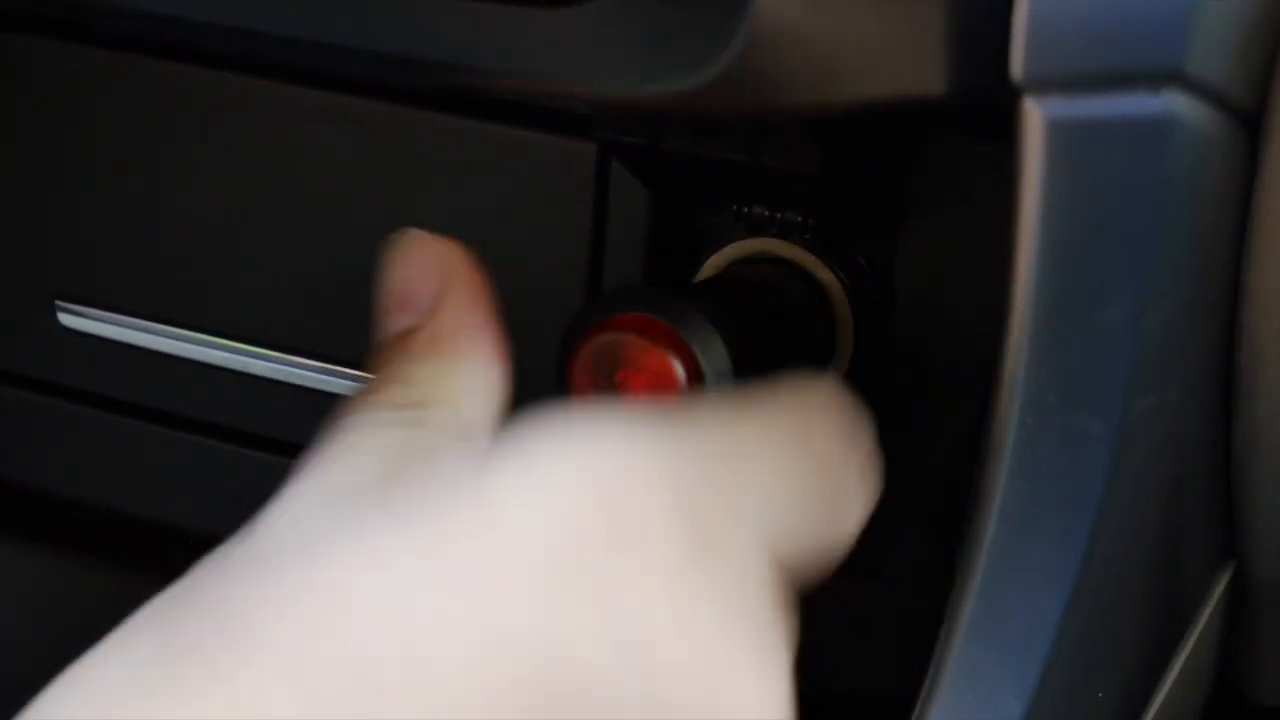
The included retrofit lead can connect to a vehicle ACC circuit so the display follows vehicle power. Fixed wiring should be performed by someone who can identify a genuine switched circuit, verify polarity with appropriate instruments, select correct circuit protection and restore trim without pinching wiring. Do not probe or tap safety, restraint, communication or unknown circuits. The device’s wide input rating is not a substitute for vehicle wiring information.
4. Secure the installation and power on
Apply the base only after the location and cable path pass every check. Hold it according to the tape instructions, allow the bond to develop and do not use the display as a handle. Cycle steering, pedals, seat and adjustable column through their ranges while stationary. Power the unit and watch for a normal startup rather than repeatedly disconnecting it. If the plug becomes hot, fits loosely, resets with vibration or causes another circuit symptom, switch off and correct the power path.
Acquire and verify satellite data
5. Wait for a fix in open sky
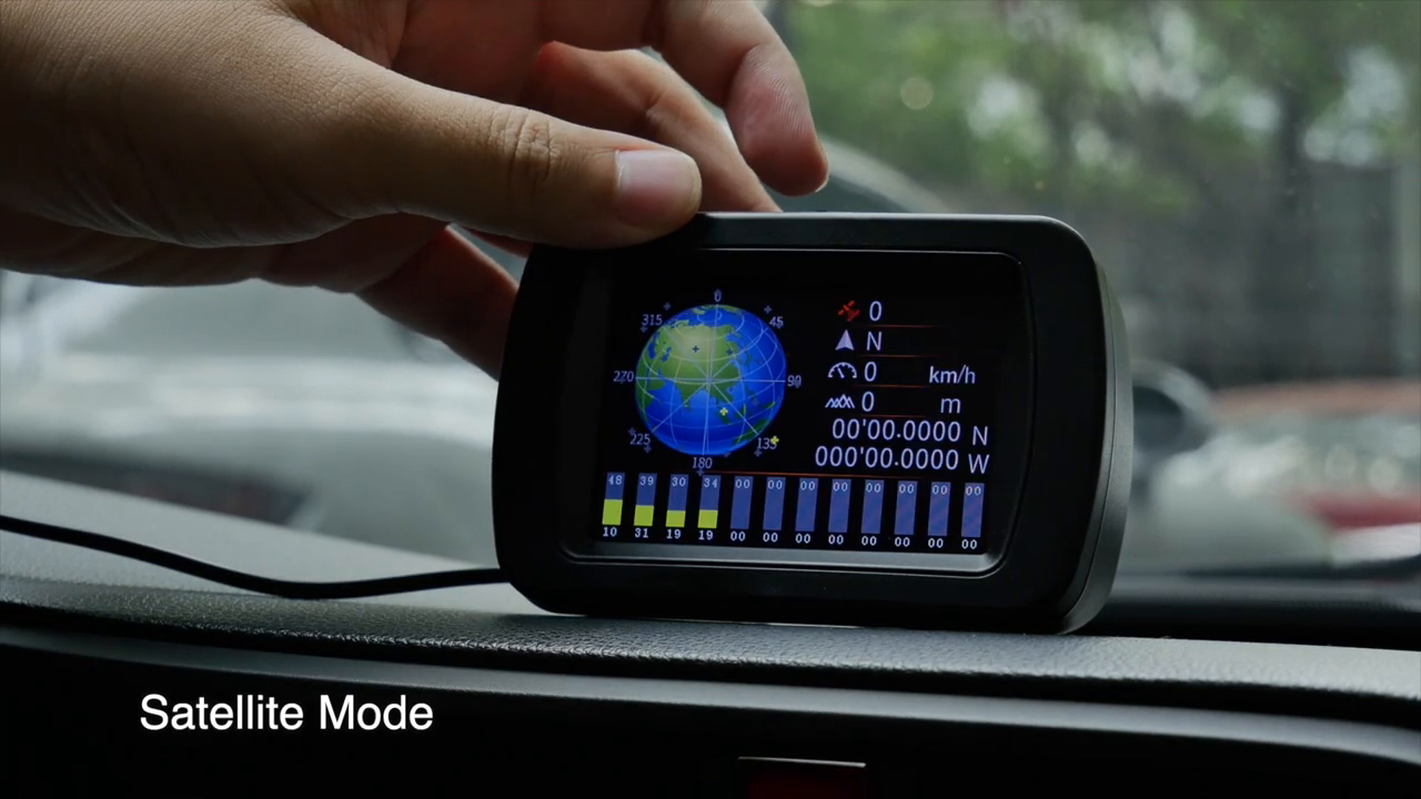
Start outdoors away from garages, metal roofs, dense tree cover and tall buildings. Leave the vehicle stationary while the receiver establishes a position. A zero speed reading by itself does not prove a good fix. Look for several mutually consistent fields: satellite count should populate, satellite time should become plausible, coordinates should settle, direction should respond once the vehicle moves and altitude should stop making large jumps. The official video shows a dedicated Satellite display for this check.
GPS performance changes with sky view. Tunnels, covered parking, steep valleys and dense urban streets can delay or interrupt reception. Direction may be unstable while stationary because satellite course commonly depends on motion. Coordinates and altitude are useful for orientation and trends, not survey work or emergency-grade positioning. Continue to use required vehicle instruments and appropriate navigation.
Use the four M85 displays
6. Learn the top control while parked
The official demonstration shows the operator using the top control to move between Driving Mode, Satellite Mode, Off-road Mode, Slope Meter Display and the settings screen. It does not clearly document every press duration or every firmware variant, so use the label and sequence in the printed manual supplied with the exact unit. Make all page changes while parked; touching a small dashboard control while moving creates needless distraction.
7. Read Driving Mode as GPS trip information
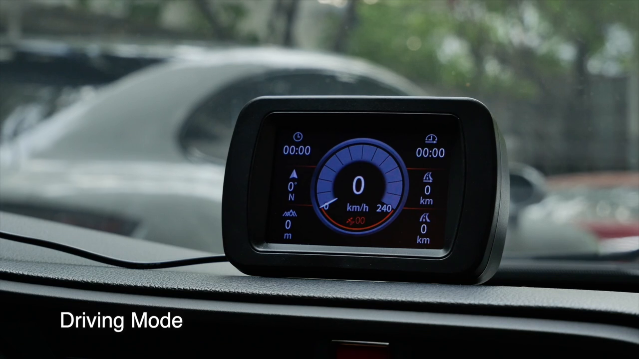
Driving Mode centers GPS speed and surrounds it with trip fields such as time and distance. After a stable fix, compare speed only on a straight, open road at a steady legal speed, ideally with a passenger recording the values. Do not calibrate during acceleration, braking, a curve or satellite reacquisition. Current distance and total distance can differ from the vehicle odometer because their source, update behavior and reset rules differ. They are convenience records unless independently validated.
8. Use Off-road Mode for direction and angle trends
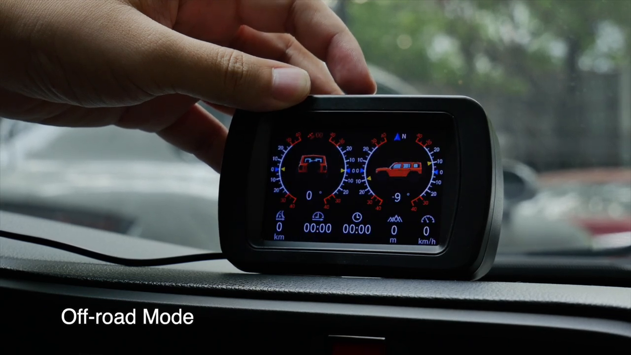
Off-road Mode combines roll and pitch graphics with compass and trip information. First verify direction response on level ground: a mild left-right body movement should affect roll in the expected direction, while a mild uphill-downhill change should affect pitch. The gallery says an alarm can activate above 30 degrees, but that value is not a safe operating limit. Vehicle geometry, load shift, tire grip, surface collapse and dynamic motion can create danger far below a displayed threshold.
Set and verify the slope reference
9. Zero only on a trustworthy level surface
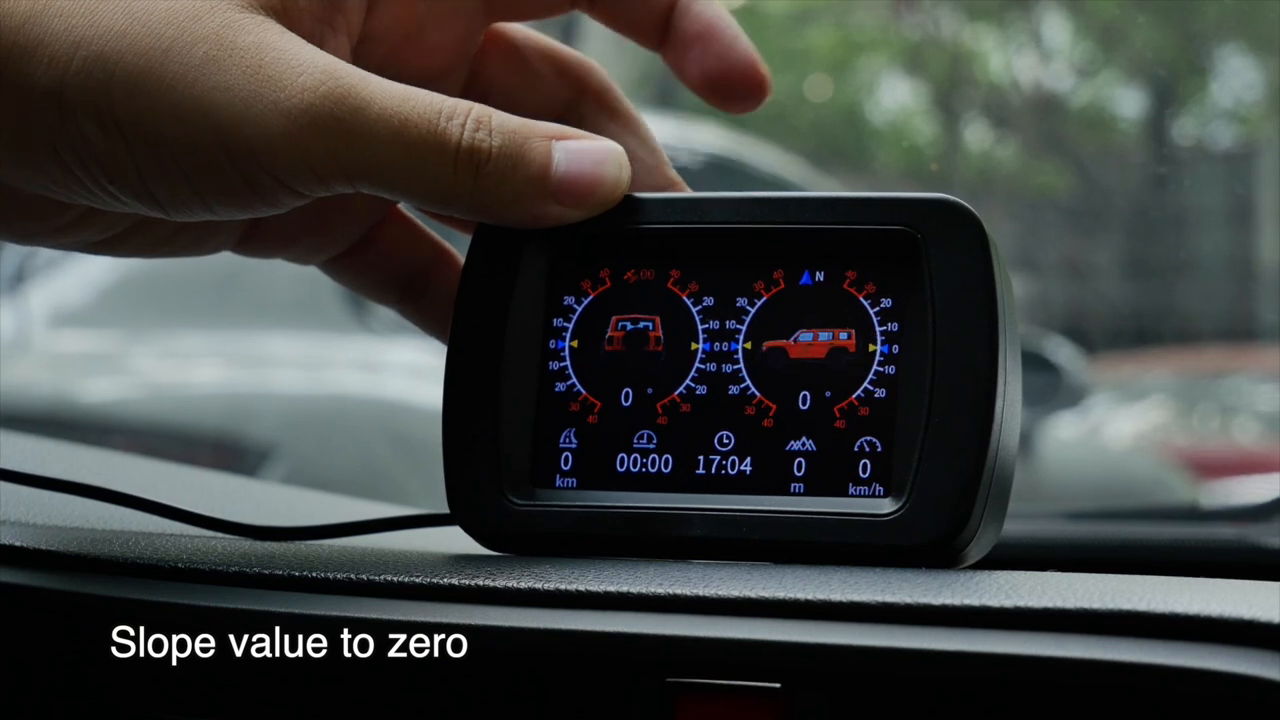
The official M85 video explicitly demonstrates a slope-value-to-zero operation from the off-road screen. Before using it, make sure the tires, suspension, load and mounting base are in the condition you intend to reference. Keep the vehicle stationary on verified level ground. Use the exact control action in the unit’s printed instructions, confirm both angle values settle at the intended baseline, then release the display without pushing the bracket out of position. Do not copy the zero gesture from M50, M60 or another firmware.
10. Verify the baseline instead of assuming it
Move the vehicle to a second known level position and compare the result. Return to the original position and look for repeatability. If the baseline changes, inspect adhesive movement, bracket flex, dashboard contour, tire pressure and cargo shift before attempting another zero. A zero command removes the current offset; it does not prove the surface is level or calibrate the sensor against a traceable angle reference.
11. Read the Slope Meter display conservatively
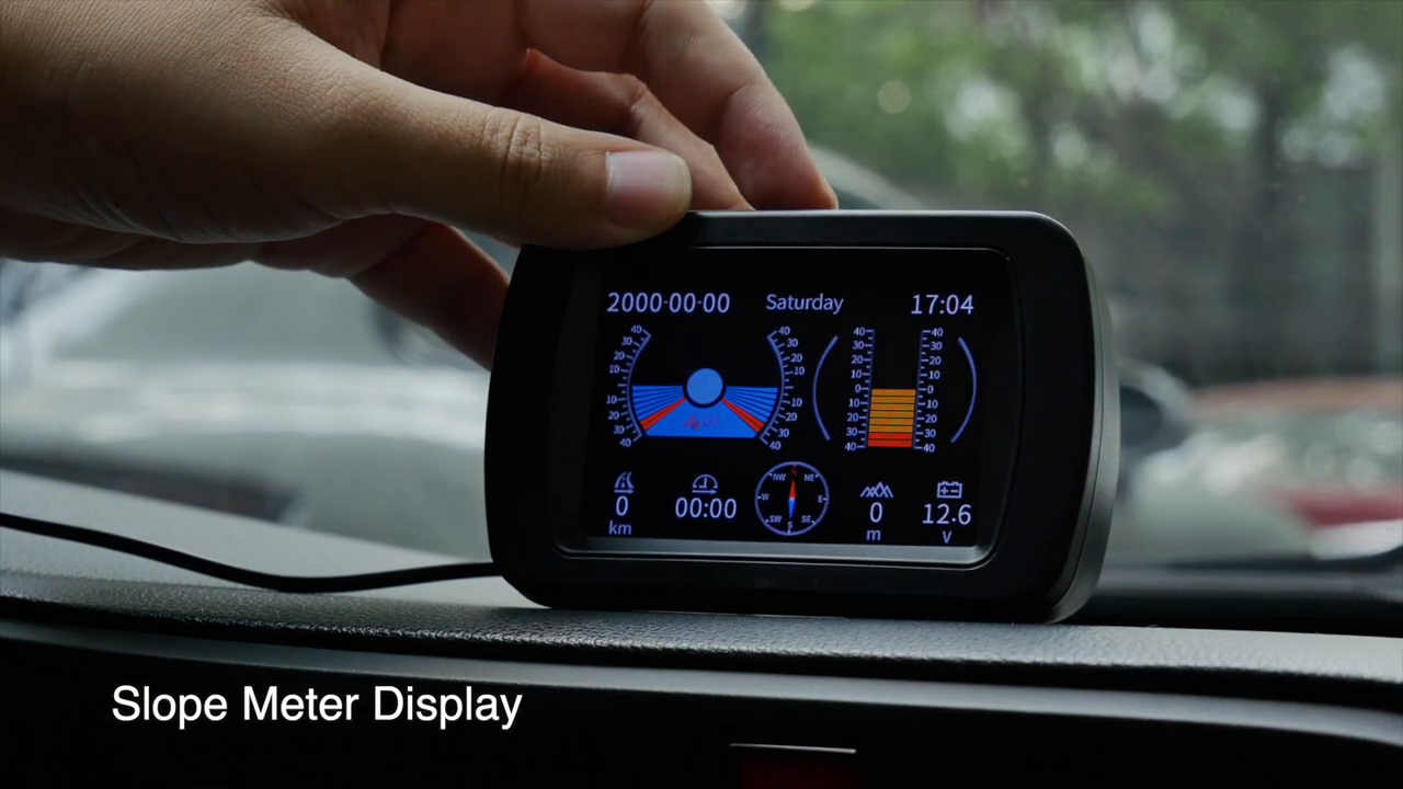
The fourth display adds graphical attitude information, date and time, compass, voltage and related fields. Use it to observe gradual changes while a qualified driver concentrates on the route. Never drive toward a threshold to test the display or alarm. Stop before interpreting an unexpected value, and compare the housing with the vehicle body: a loose display can show a real sensor change that is unrelated to vehicle angle.
Review settings carefully
12. Change one setting at a time
The settings screen shown in the official video includes Language, Unit, Speed alarm, Speed adjust, Adjust time and Theme style. A second page shows System sound, LCD brightness, Standby delay, Set ODO and Restore. Record the original values before changing anything. Verify the units first so a speed-alarm number is not interpreted in the wrong system, and set time against the local time zone rather than changing the clock repeatedly while GPS is still acquiring.
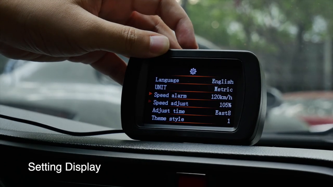
Leave Speed adjust at its baseline until a repeatable comparison proves an offset under stable GPS conditions. Brightness should keep information legible without producing glare; automatic brightness still needs a clear light sensor. Standby delay affects shutdown behavior and should be checked against the actual vehicle power circuit. Set ODO and Restore can change stored information or configuration, so do not select them casually. If the menu wording or available options differ, the screen on the exact device takes priority.
Verify the M85 after installation
Take a short controlled drive, then park and recheck the complete system. Confirm the base has not rotated, the cable has not moved toward controls, the accessory plug remains cool and secure, satellite fields reacquire normally and the angle baseline returns on level ground. Switch the vehicle off and observe whether the unit shuts down as expected. If it remains awake on a constant-power socket or after the configured delay, disconnect it rather than risking battery discharge.
Troubleshoot by symptom
| Symptom | Check first |
|---|---|
| No power | Accessory socket or ACC circuit, fuse, polarity, cable seating and the 5–35 V device range |
| Repeated restarts | Loose charger, pinched cable, voltage drop or unsuitable retrofit connection |
| Speed stays at zero | Open-sky reception, satellite count and sufficient movement after acquisition |
| Direction unstable while stopped | Move safely after a stable fix; GPS course may require motion |
| Pitch and roll appear reversed | Housing rotation relative to the vehicle centerline |
| Zero changes between drives | Mount movement, flex, tire pressure, load or an unreliable level surface |
| Voltage differs from a meter | Accessory-circuit wiring and contact drop; verify at the specified test point |
| Display remains on after key-off | Constant-power socket, ACC choice and standby-delay setting |
| Menu differs from the video | Follow the exact unit firmware and supplied printed instructions |
Final M85 checklist
- Vehicle circuit and power method identified before connection
- Display mounted rigidly, low and square with the centerline
- Road view, warnings, instruments, vents and airbags unobstructed
- Cable clear of pedals, steering, seats, sharp edges and moving trim
- Rear mini-USB and car charger or protected ACC connection secure
- Satellite count, time, coordinates and direction plausible
- Four displays reviewed while parked
- Slope reference set only on verified level ground
- Pitch and roll directions checked under mild controlled conditions
- Speed compared only with a stable fix and steady legal motion
- Original settings recorded before adjustment
- Angle alarm never treated as a safe terrain limit
- Key-off shutdown, standby and battery behavior verified
- Mount, cable and baseline rechecked after the first drive
A dependable M85 setup is less about displaying every available number and more about knowing which reference supports it. Give the receiver a clear sky view, mount the sensor square, establish zero on genuinely level ground and keep power wiring out of the driver’s workspace. When GPS, angle or voltage information becomes uncertain, stop and verify that source before changing settings or drawing a vehicle conclusion.











Comments 0
Questions, fixes, and real-world diagnostic notes from readers.
Be the first to share a diagnostic result or ask a follow-up question.