
How to Use the FXTUL M7 Motorcycle Diagnostic Tool

The FXTUL M7 motorcycle diagnostic tool can scan supported motorcycle control units, preserve a whole-vehicle report, read fault and freeze-frame data, graph live values, record screen events and capture a support log. The useful workflow is not “connect and clear.” It is scan, record, repair and verify.
The M7 does not make one cable, identity route, normal value or service-reset sequence universal. Connector location, key state, available modules, test prerequisites and requested service values change by motorcycle. Use current exact vehicle/system/function coverage and the motorcycle’s service information whenever a step becomes vehicle-specific.
Updated August 28, 2026.
In this guide
- Know what each evidence tool preserves
- Prepare the motorcycle, kit and job record
- FXTUL M7 step-by-step diagnostic workflow
- Use Battery as a voltage-trend and connection check
- Update M7 software by one controlled route
- Capture a clean support log
- Troubleshoot without destroying evidence
- What a complete M7 diagnostic job looks like
Know what each evidence tool preserves
The M7 provides several recording tools because they solve different problems:
| Tool | What it preserves | Best time to use it |
|---|---|---|
| Report | Whole-vehicle module and fault status from Quick Test or Control Unit | Immediately after the first complete scan |
| Long-press F1 screenshot | One visible screen, such as a code, data list, waveform or result | At a decisive state that must be shown exactly |
| Long-press F2 event recording | A sequence on supported module, fault-code or data-stream screens | When an intermittent value or menu sequence must be replayed |
| Log | Diagnostic-session data written for technical support | When reproducing one defined communication or software problem |
Use the smallest tool that preserves the evidence you need. A screenshot does not replace a complete report, and a support log should not remain enabled for every routine job.
Prepare the motorcycle, kit and job record
Have the exact motorcycle service information, current M7 vehicle/system/function coverage, the required labeled adapter, a stable power plan permitted for that motorcycle and a job record ready. Record the make, model, year, VIN when applicable, odometer, complaint, warning lamps, recent repairs, battery condition and the conditions that reproduce the symptom.
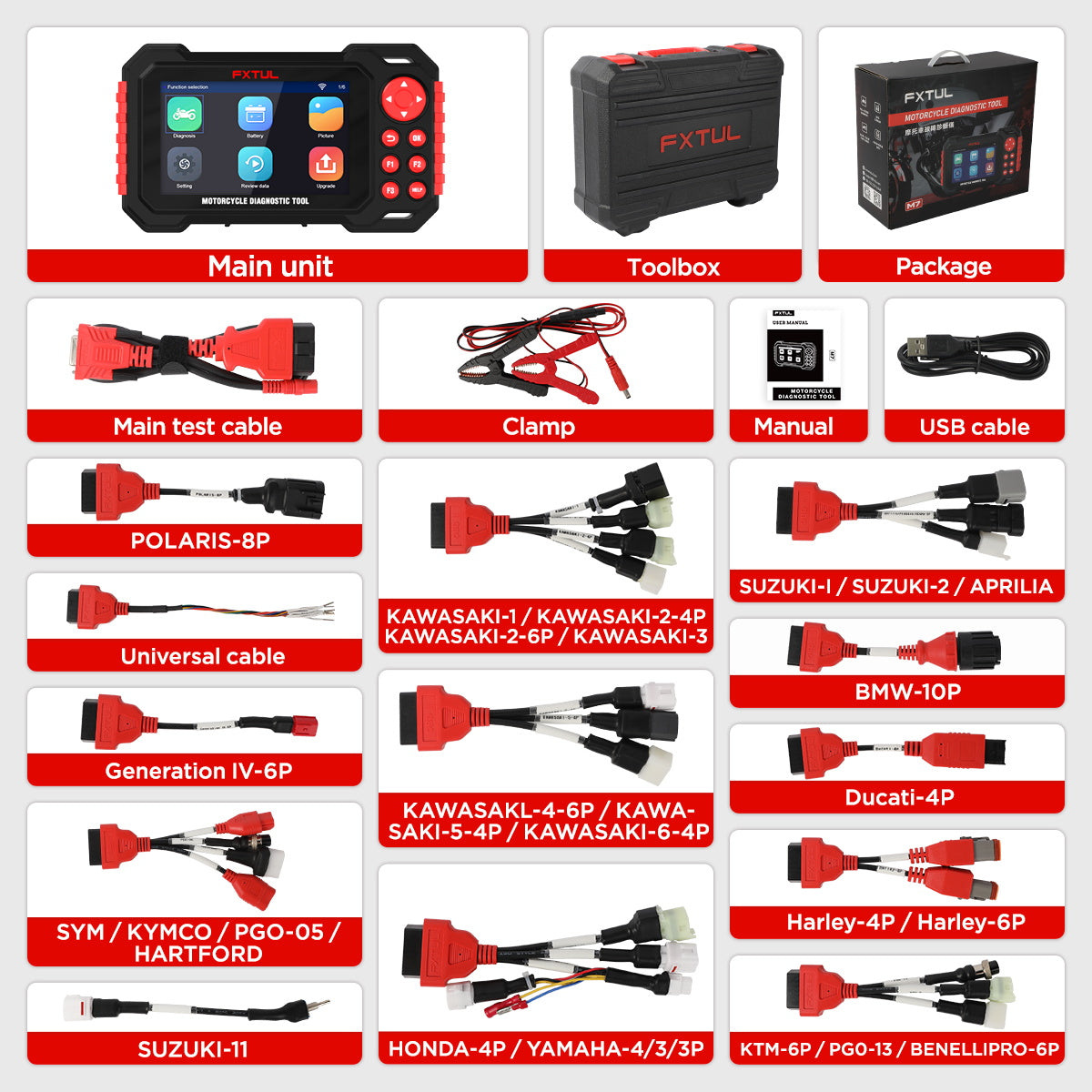
Inspect the M7 housing, main cable, adapter branches, battery clamp when the exact adapter requires it, USB cable and connector terminals. Inspect the motorcycle connector for corrosion, water, contamination, bent pins, pushed-back terminals and earlier probing damage. A connector that looks similar but requires force is wrong or damaged.
Stabilize the motorcycle through its exact service procedure. Control fuel vapor, exhaust, hot surfaces, fans, chains, belts, wheels and unintended movement. Decide who controls the ignition and engine before anyone works near moving or heated parts.
FXTUL M7 step-by-step diagnostic workflow
Step 1: Record the exact M7 and installed versions
Confirm that the case, device label and current product identity all describe M7. Inventory the actual adapters by their printed labels; do not identify a lead only by color, pin count or apparent connector shape. If cables from multiple kits have been mixed, isolate uncertain items before the job.
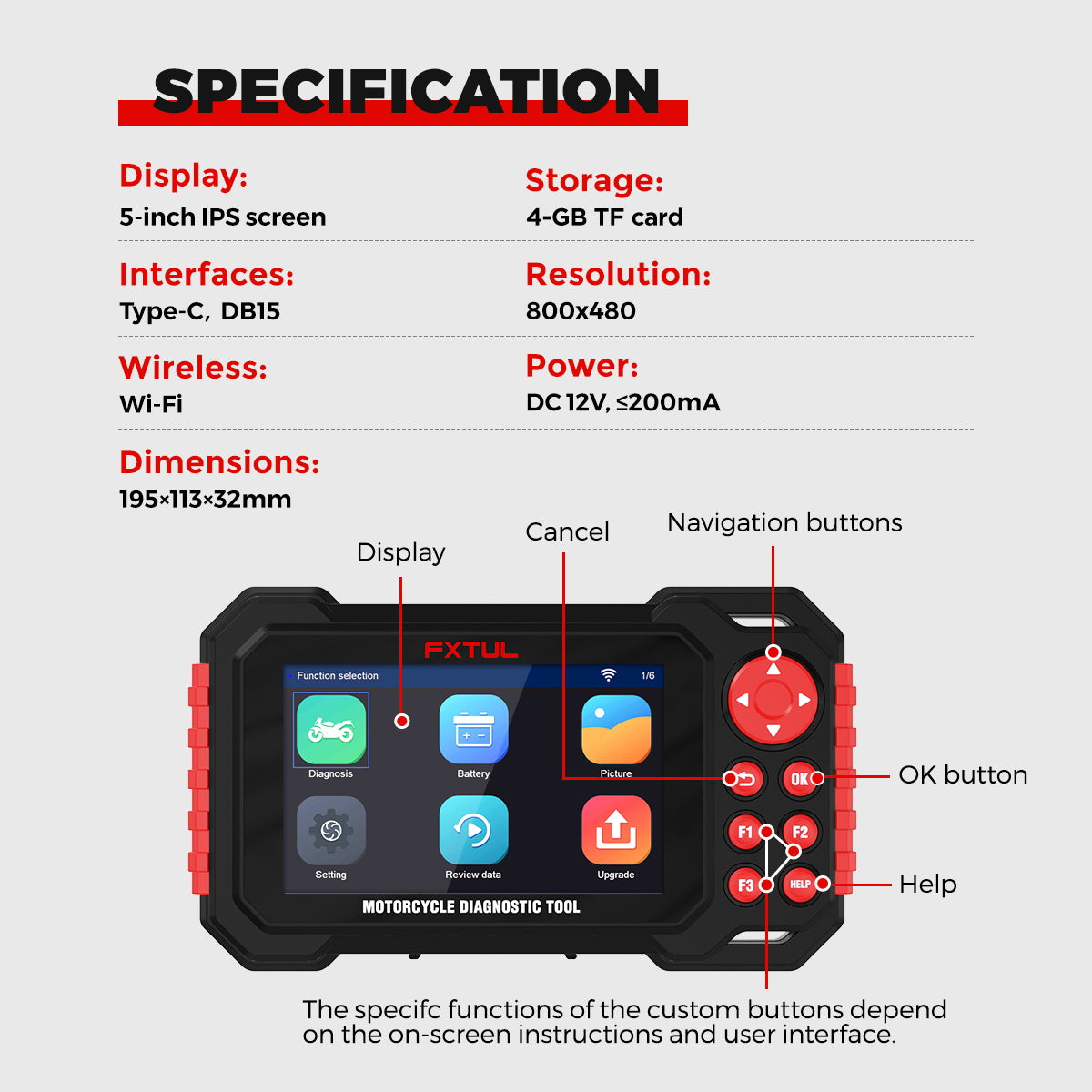
Power the M7 through an approved diagnostic connection or the update connection described later. Open Upgrade → About and record Menu Version, App Version and Software Package Version. These identifiers make a later coverage, update or support question reproducible.
Completion check: The job record identifies the exact M7, every relevant displayed version and the physical labeled adapter set.
Step 2: Confirm exact vehicle, system, function and adapter coverage
Check current coverage for the exact make, model, year and target control unit—not only the motorcycle brand. Confirm that the function you need is covered as a separate decision. A scanner may communicate with the engine controller yet not expose a particular ABS bleed, adaptation or maintenance routine on the same motorcycle.
Match the required adapter name to the label on the cable in your hand. The M7 manual notes that most interfaces do not require the battery clamp, while some special interfaces do. Use the clamp only when the exact labeled adapter and current procedure require that power route.
Stop: Do not continue if the only match is a similar model, an assumed pinout, an unlabeled adapter or a function shown only in a generic promotional list.
Step 3: Stabilize the motorcycle and inspect the exact connector
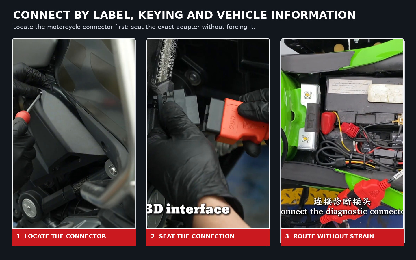
Use the motorcycle service information to locate the diagnostic connector and determine whether a seat, side cover, footrest panel or front panel must be removed. Identify the connector keying and pin orientation from the approved procedure; do not probe unknown terminals to discover a diagnostic socket.
Support removed trim and route the future cable path away from the exhaust, steering stops, fan, chain, belt and wheel. Follow the exact procedure for ignition, engine state and battery support. If the engine will run, use effective exhaust extraction and control the driven wheel.
Completion check: The motorcycle is stable, the exact connector is serviceable and the complete scan can be powered without loading the harness.
Step 4: Connect the labeled adapter without forcing it
Keep the ignition in the state required by the motorcycle procedure. Join the M7 main lead to the exact labeled adapter, align all keyed features and seat connectors by their housings. If the exact interface needs the supplied battery clamp, confirm polarity and approved connection points before attaching it.
Connect to the motorcycle only after checking the full cable path. Support the M7 so its weight does not hang from the vehicle connector. If a latch will not seat, a terminal moves or the connection must be twisted, disconnect and resolve the mismatch. Never file a key, bridge pins or improvise an external supply.
Completion check: Every connection is fully seated, correctly powered, strain-free and clear of heat and movement.
Step 5: Set language and units; leave Log off unless needed
From Setting, select the installed language and metric or imperial units that make the job record unambiguous. Confirm the Wi-Fi state but do not begin an update during a vehicle diagnosis.
Keep Log off during normal scanning unless you are reproducing a defined problem for support. Log creates a separate diagnostic record and should be enabled immediately before the controlled reproduction described later. Return to Upgrade → About and confirm the versions still match Step 1.
Completion check: Language, units and versions are recorded, and Log has a stated purpose rather than being left on by habit.
Step 6: Select only the identity route shown for the exact motorcycle
Open Diagnosis, select the correct brand and follow the identity method the installed package presents. Depending on the exact brand and software, the route may use system selection, specific model information or supported VIN identification.
Verify that the resulting model, year, engine or system identity agrees with the motorcycle and service record. Do not select a nearby year or different motorcycle just to make a module appear. If VIN identification returns an unexpected vehicle or fails, return to exact coverage and connector checks instead of forcing the result.
Completion check: The M7 reaches an exact vehicle identity or a service-information-supported system route without guessing.
Step 7: Choose Quick Test or Control Unit by interface layout
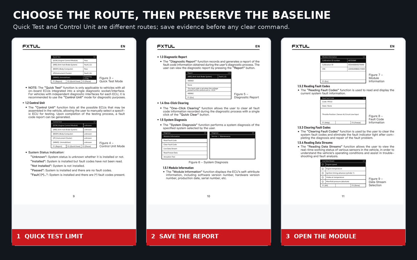
Use Quick Test when the motorcycle’s assembled ECUs are integrated into one diagnostic socket. Let it retrieve the available system and fault status across that shared interface.
Use Control Unit when the motorcycle has independent diagnostic interfaces for different ECUs, or when the exact procedure directs you to one known system. The list can include systems that are unknown or not installed, so treat its status labels as scan results rather than proof that every listed module exists.
Completion check: The selected mode matches the motorcycle’s physical diagnostic architecture, not merely the shorter menu path.
Step 8: Run the baseline scan without Quick Erase
Allow Quick Test—or the required Control Unit checks—to finish unless an unsafe condition or the motorcycle procedure requires a stop. Record every system shown as passed, faulted, installed, not installed, unknown or not communicating. A missing communication path can be as important as a stored code.
Do not press Quick Erase during the baseline. One-click clearing can remove the original fault information across scanned systems before you understand the pattern.
Completion check: The initial scan is complete, all status results are visible and no clear command has been accepted.
Step 9: Save Report and capture the decisive screen
Open Report and preserve the complete pre-clear result according to workshop policy. Include vehicle identity, modules, communication states, code numbers/descriptions and test conditions. Then long-press F1 on a decisive screen to create a screenshot. Use Picture later to confirm the file exists and is readable.
A code description names a monitored condition or circuit; it does not prove which component failed. Compare the whole-vehicle pattern with low-voltage history, recent work and the original complaint before forming a theory.
Completion check: The baseline report and at least one necessary screen state can be reconstructed without repeating or clearing the first scan.
Step 10: Enter the affected module and preserve identity, DTC and freeze data
Select the affected Control Unit, then open Module Information and record identifiers the controller provides, such as software, hardware, calibration, serial or VIN information. If module identity conflicts with the vehicle record, stop and resolve the selected route, installed controller or software coverage.
Open Read Fault Code and capture every displayed code and status. Save Read Freeze Data before clearing when it is available. Freeze data records conditions associated with a fault event; it does not prove that each value was valid or remains present now.
Completion check: Module identity, all displayed DTC states and available freeze data are preserved with their test conditions.
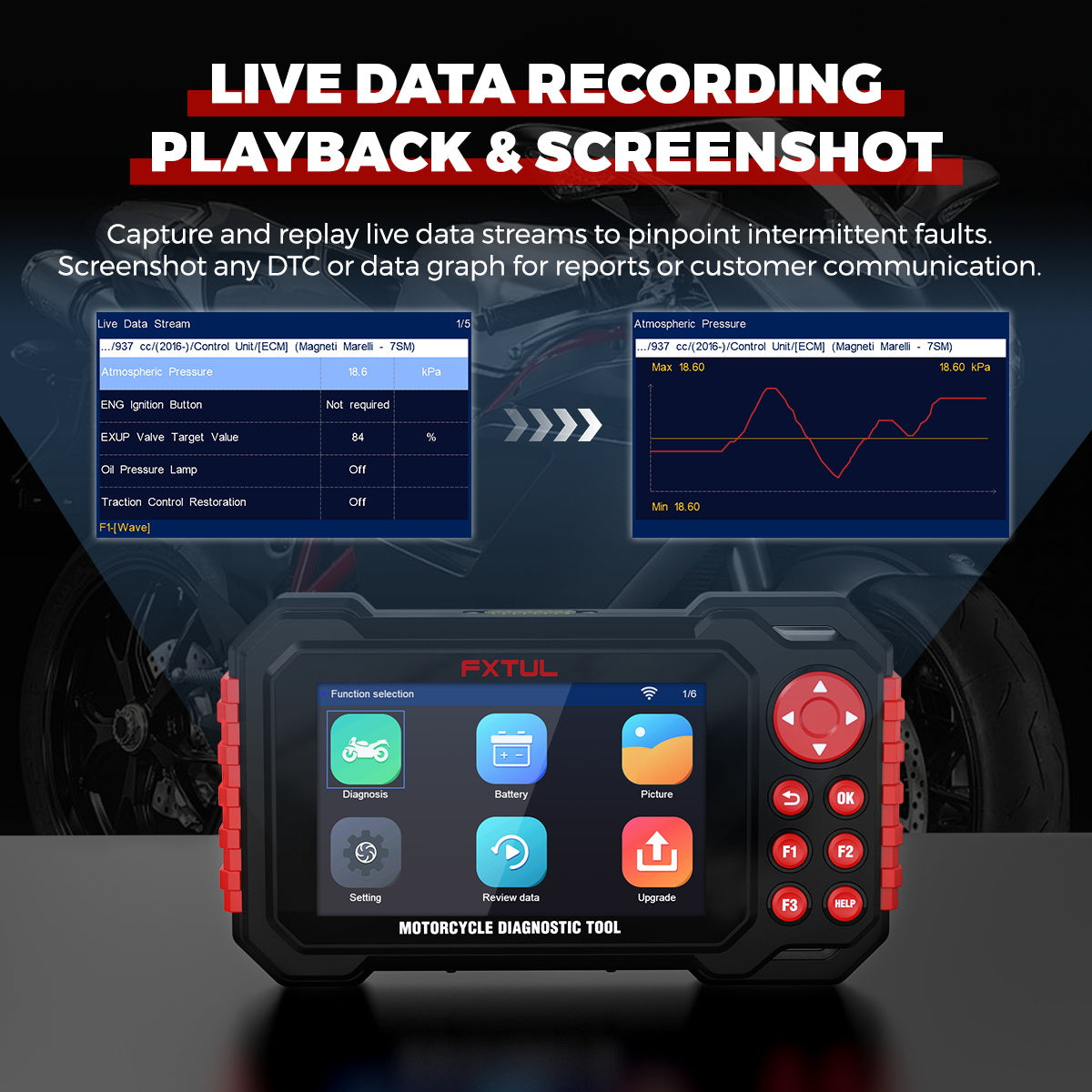
Step 11: Select a compact live-data set that tests one theory
Open Live Data Stream and select only parameters needed to answer a written diagnostic question. A compact group—such as engine speed, supply voltage, one command and its feedback—is easier to time-align than every available value.
Define the expected range and operating condition from the motorcycle procedure before calling a value abnormal. Compare important values with a direct measurement or another independent signal. If the engine must run or a control must move, assign one person to the motorcycle and one to the M7. Never read the scanner while riding.
Completion check: The live-data capture tests one stated theory under known conditions and includes units and supporting evidence.
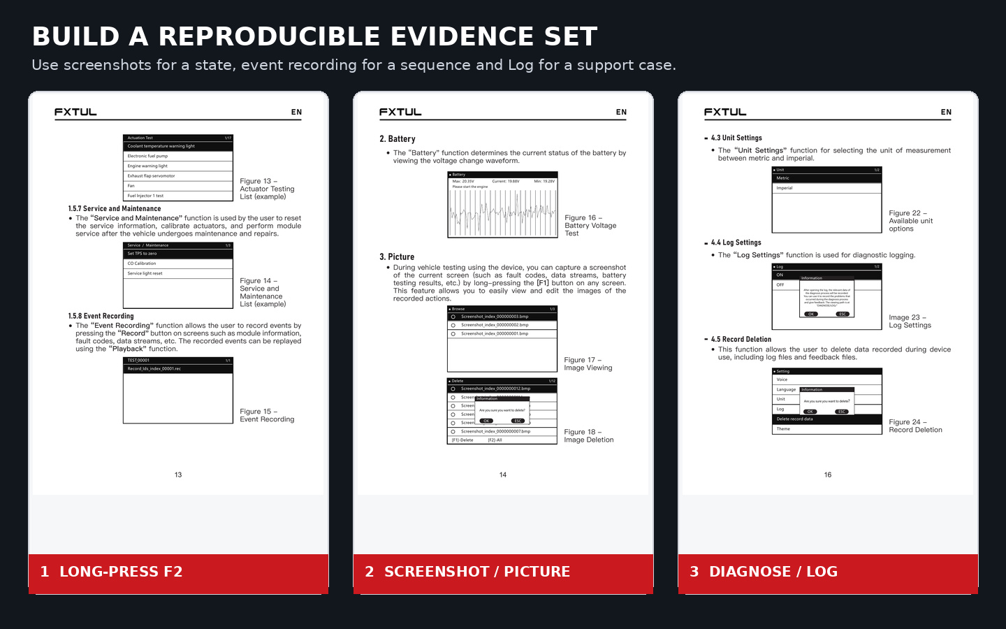
Step 12: Record and replay an intermittent event with long-press F2
On a supported module, code or data-stream screen, long-press F2 to begin the event recording. Reproduce one defined symptom under controlled workshop conditions, note the exact trigger time and end the capture as the installed screen directs.
Open Review data or the available Playback route and replay the event before leaving the job. Confirm that the relevant screen, values and timing were actually captured. A long recording without a marked trigger is harder to interpret than a short controlled event.
Completion check: The recording replays, contains the intended trigger and is linked to the same vehicle, conditions and diagnostic question.
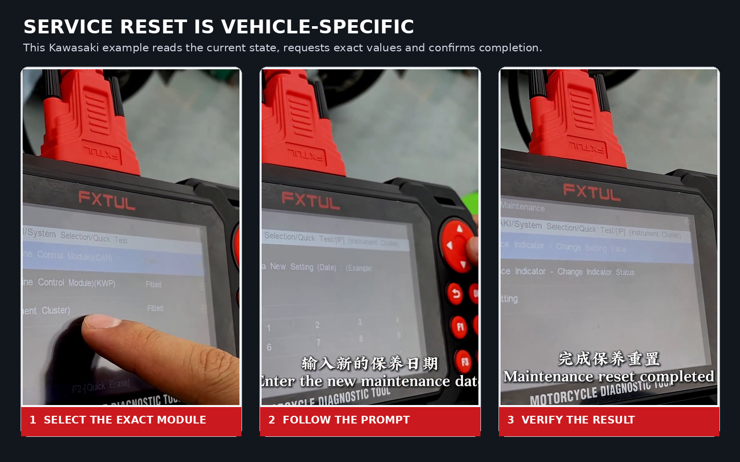
Step 13: Treat actuation and Service / Maintenance as vehicle-specific procedures
The selected module may expose Actuation Test or Service / Maintenance. These commands can run a pump, fan, injector, lamp or motor, reset a maintenance value, calibrate an actuator or change stored state. Availability and prerequisites depend on the exact motorcycle and control unit.
Official M7 cases illustrate the boundary: a Kawasaki sequence selects the instrument cluster, reads current mileage, requests maintenance date and mileage, confirms the change and verifies completion; a BMW sequence presents different service choices and value prompts. Neither sequence supplies reusable values for another motorcycle.
Before accepting a command, obtain the exact service procedure and verify support position, fluid level, temperature, ignition/engine state, power stability, access clearance, expected response, exit condition and recovery path. Keep people, fuel and tools clear of anything that may move, heat, spark or pressurize.
Stop: If any prerequisite, requested value, supported system or recovery step is uncertain, do not run the function.
Step 14: Repair the verified cause and preserve the comparison
Use the report, DTC, freeze data, screenshot, event capture, wiring information and direct tests to identify the cause. Repair the verified fault through the motorcycle procedure. Do not replace a sensor, controller, pump or hydraulic part solely because its name appears in a code or menu.
Save final pre-repair measurements needed for comparison. Restore every connector lock, ground, fuse, hose, cover and removed component required for a safe post-repair check.
Completion check: The repair follows the proven cause, the motorcycle is reassembled for verification and the before/after record remains intact.
Step 15: Clear only after repair, then repeat the scan and operating conditions
Use Clear Fault Code only after the original evidence is saved and the repair is complete. Accept the command only when loss of fault and freeze information is intentional. Cycle ignition only as the motorcycle procedure requires.
Repeat the same Quick Test or Control Unit route, then reproduce the original operating conditions safely. Compare communication state, codes, live data and symptom behavior with the baseline. Capture a final report or screenshot. A warning lamp that turns off immediately after clearing is not proof of repair.
Completion check: The original symptom is tested under the required conditions, the final scan is saved and no unresolved result is hidden by clearing.
Use Battery as a voltage-trend and connection check
Open Battery to view the M7 voltage-change waveform under the exact motorcycle procedure. Use the display to notice an obvious interruption, unstable connection or large supply change that could explain communication loss.
Do not use the screen alone to condemn the battery, starter or charging system. The manual supplies no measurement accuracy, load-test criteria or motorcycle-specific pass/fail threshold. Confirm any conclusion at the correct measurement points with a suitable meter and the motorcycle procedure.
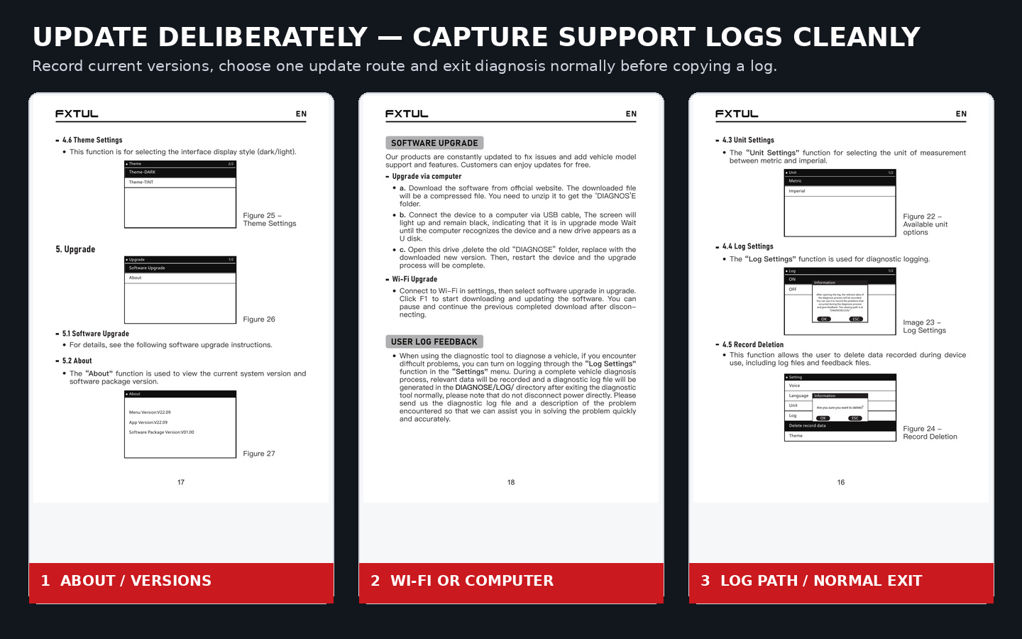
Update M7 software by one controlled route
Record Menu Version, App Version and Software Package Version under Upgrade → About before starting. Obtain an exact current M7 package or use the installed Wi-Fi update route. Maintain stable scanner power, finish one route completely and verify all versions after restart.
Wi-Fi update
- Open Setting → Wi-Fi and connect to a stable network.
- Open Upgrade → Software Upgrade.
- Press F1 when the installed screen offers the download/update command.
- Keep the device powered until the installed process reports completion. If the connection is interrupted, use the screen’s supported resume behavior rather than beginning an unrelated package transfer.
- Restart normally, record the new versions and recheck exact vehicle/function coverage.
Computer update
- Download and unpack an exact current M7 update package through the current FXTUL route; confirm it contains the intended
DIAGNOSEfolder. - Connect the M7 to a computer with the data-capable USB cable. Its screen can remain black while the computer recognizes a new drive.
- Verify the M7 drive identity before changing any folder.
- Replace the drive’s old DIAGNOSE folder with the exact new folder.
- Allow the complete copy to finish, disconnect the drive safely and restart the M7 normally.
- Record the versions under About and confirm that the expected menu and exact coverage are present.
Do not mix Wi-Fi and computer procedures mid-update, substitute another model’s package or remove power during a file operation.
Capture a clean support log
Use Log when an exact communication, menu or software problem needs technical support—not as a permanent background recorder.
- Write down the motorcycle identity, M7 versions, adapter, target system, symptom and exact reproduction steps.
- Open Setting → Log → ON immediately before the test.
- Perform one complete controlled diagnostic reproduction and note its time.
- Exit the diagnostic function normally. Do not cut power to end the session.
- Connect the M7 to a computer and copy the matching file from DIAGNOSE/LOG/.
- Verify the file time and preserve it with the problem description, screenshots and relevant job record.
- Return Log to OFF when the support capture is complete.
If no log appears, repeat only after checking that Log was enabled, diagnosis was exited normally and the session completed before power was removed.
Troubleshoot without destroying evidence
| Symptom | Controlled next check | Do not do |
|---|---|---|
| M7 does not power or communicate | Verify exact connector, adapter label, required clamp route, permitted key state, vehicle-side supply and cable seating | Do not bridge unknown pins or improvise power |
| Motorcycle is absent from the menu | Recheck installed versions and current exact coverage; use only the identity method the exact menu presents | Do not choose a similar motorcycle to enter a module |
| Quick Test misses expected systems | Confirm whether the motorcycle uses one integrated socket or independent ECU interfaces; use Control Unit when required | Do not treat every listed unknown system as installed |
| One module will not communicate | Compare the whole-vehicle pattern, module power/ground/network procedure and recent work | Do not condemn the controller from non-communication alone |
| Codes return immediately | Preserve status and freeze data, then diagnose active power, ground, circuit or network conditions | Do not repeat clear commands |
| Live data looks implausible | Confirm units, parameter definition, operating condition and a direct supporting measurement | Do not treat one displayed number as a failed sensor |
| Event recording misses the symptom | Shorten the test, define one trigger and verify playback before repeating | Do not create an unmarked long recording |
| Service function is absent or requests unfamiliar values | Confirm exact system/function coverage and the vehicle procedure | Do not copy BMW, Kawasaki or another motorcycle’s values |
| Update drive does not appear | Verify a data-capable USB cable/port and identify the expected M7 drive | Do not delete a folder on an uncertain drive |
| Support log is missing | Confirm Log was on, reproduce one full session and exit diagnosis normally | Do not remove power to finish logging |
What a complete M7 diagnostic job looks like
A complete M7 job identifies the exact tool, installed versions, current motorcycle/system/function coverage and physical labeled adapter before connection. It chooses Quick Test or Control Unit from the motorcycle’s interface architecture, saves the first report and decisive screen before any clear command, and uses a compact evidence set to test one cause.
The job closes with a verified repair, an intentional clear only after evidence preservation, a repeat scan under the original operating conditions and a saved final result. Screenshots, event recording and Log then serve clear purposes inside that record instead of becoming disconnected files. That is how the FXTUL M7 motorcycle diagnostic tool supports a repeatable scan–record–repair–verify workflow.











Comments 0
Questions, fixes, and real-world diagnostic notes from readers.
Be the first to share a diagnostic result or ask a follow-up question.