
2014 Ford B-Max P0102 After a New MAF: One Feed Wire and One ECU Ground Were Both Bad

New Maf, Same P0102? Test Feed And Ground
A 2014 Ford B-Max 1.0 EcoBoost carried P0102 and a mass-airflow sensor that had already been replaced. The warning remained. That history makes the new sensor tempting to distrust, but it also creates a better question: does the sensor have every condition it needs to work? In this case, the answer failed twice—first at the supply and then at the ground.
The useful first tool class is an automotive meter or scope that can examine the identified feed, ground and digital output while the connector remains loaded. The AUTOOL DM303 is one accessible example for those bounded checks once Ford wiring information defines the pins. DM303 can support identified power, ground, continuity, voltage-drop and accessible MAF waveform checks using Ford wiring data; it cannot prove an ECU driver has failed from one unloaded voltage, authorize a permanent ground reroute or replace Ford circuit tests and calibration checks.
Repairing a broken 12-volt feed was real progress, not a failed diagnosis. The MAF still stayed silent because its ECU-provided ground sat near battery voltage. A controlled ground test restored the sensor’s digital output, and the final circuit repair kept the warning off. The lesson is to retest the whole circuit after every correct fix rather than demanding that one fault explain everything.
Quick answer: A replacement MAF did not cure P0102 because the circuit had two faults: an open 12-volt feed and an ECU-provided ground held high. Repairing both restored output.

In this guide
- Do not let P0102 turn the MAF into a parts order
- Map every MAF wire before back-probing
- Repair the missing 12-volt feed first
- Retest the complete circuit after the first fix
- Treat 12 volts on ground as a loaded-circuit clue
- Prove the ECU ground path before changing it
- Complete a durable circuit repair
- Verify airflow, warning status and repeat starts
Do not let P0102 turn the MAF into a parts order
P0102 says the controller saw an airflow circuit signal below its expected range. It does not say that the sensing element is the only possible cause. Save the code status and freeze-frame data, inspect the replacement part number and connector, and look for disturbed wiring around the airbox. Check that the intake path is assembled and the engine is safe to run. If wiring insulation is melted, a feed is shorted or the engine will not idle safely, stop before adding power. A second MAF would still be unable to work without a complete circuit.
Map every MAF wire before back-probing
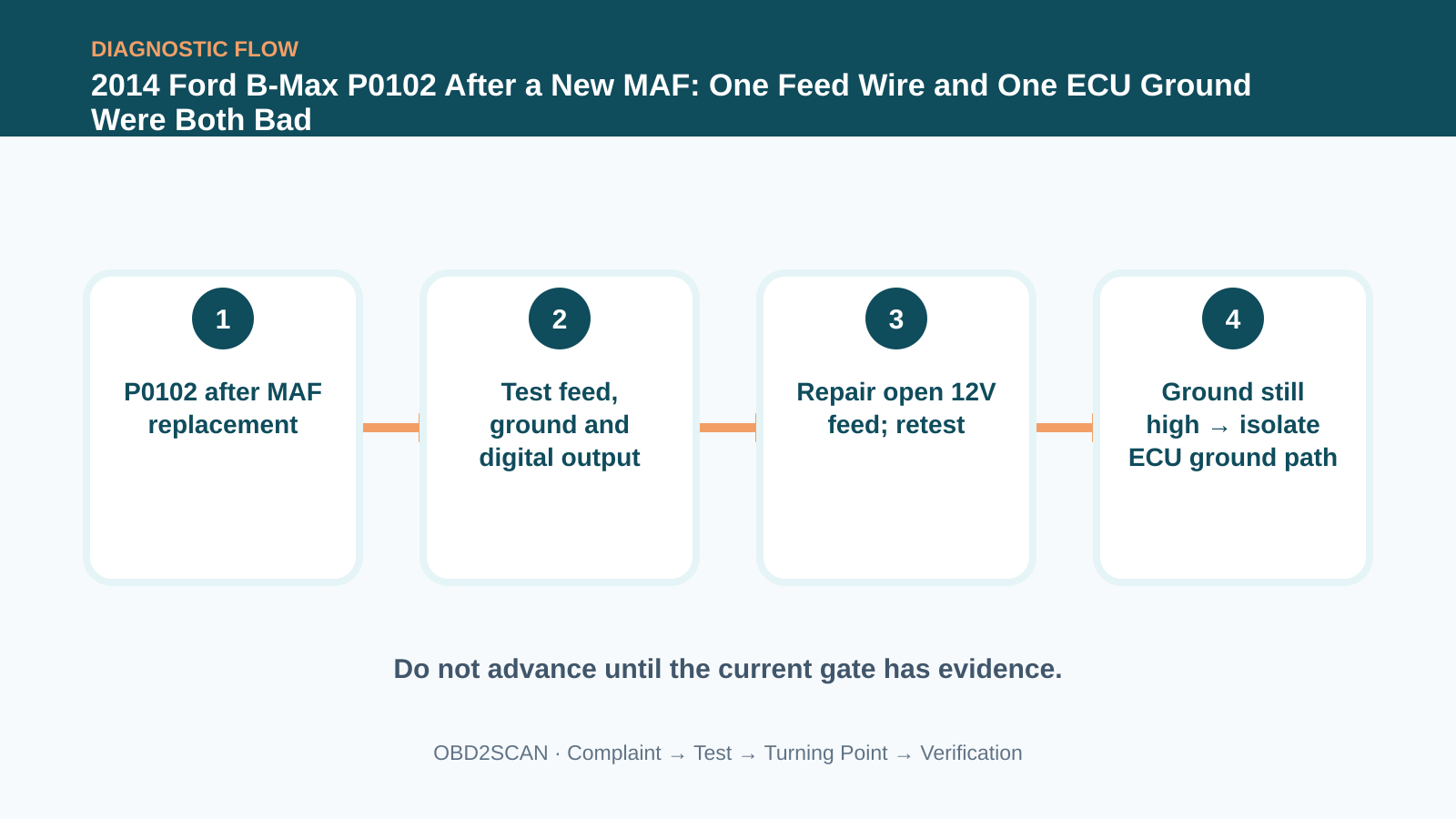
Use the diagram to label every terminal by function: supply, sensor ground, signal and any shared reference or shield. Record key-off, key-on and running expectations before touching the connector. Back-probing an unknown pin or applying power because its color looks familiar can damage the ECU. The early sequence is simple: confirm the battery and main grounds, verify the feed under load, measure ground voltage drop while the sensor is operating, and observe whether the digital output changes with airflow. Those questions are stronger than an unplugged resistance reading.
Repair the missing 12-volt feed first
The 12-volt feed was absent because a conductor had broken. Repairing it meant exposing enough sound copper, protecting the joint from strain and moisture, and restoring the loom route so the same bend would not reopen it. Then the circuit had to be tested again with the MAF connected. Seeing supply voltage return proves only that one requirement is present. It does not prove the ground can carry current, the signal wire reaches the ECU or the replacement sensor is producing a readable output.
Retest the complete circuit after the first fix
After the feed repair, the remaining readings became more informative. The ground terminal was close to 12 volts, a value that should make a technician pause. A ground wire is not judged by its name; it is judged by voltage difference while current flows. Check from the sensor ground to battery negative and then along the path toward the ECU. Also confirm the ground is not shared with another load that is back-feeding it. Disconnecting modules at random can erase the loaded condition, so record each state.
| Evidence | What it supports | What it does not prove |
|---|---|---|
| P0102 returns | Airflow circuit still reads low | Replacement MAF is defective |
| No 12V at MAF | Supply path is open or unloaded | ECU ground is healthy |
| Feed repaired, no output | A second requirement is missing | First repair was unnecessary |
| Ground near 12V under load | Ground path cannot hold reference | Exact failure location without isolation |
Treat 12 volts on ground as a loaded-circuit clue
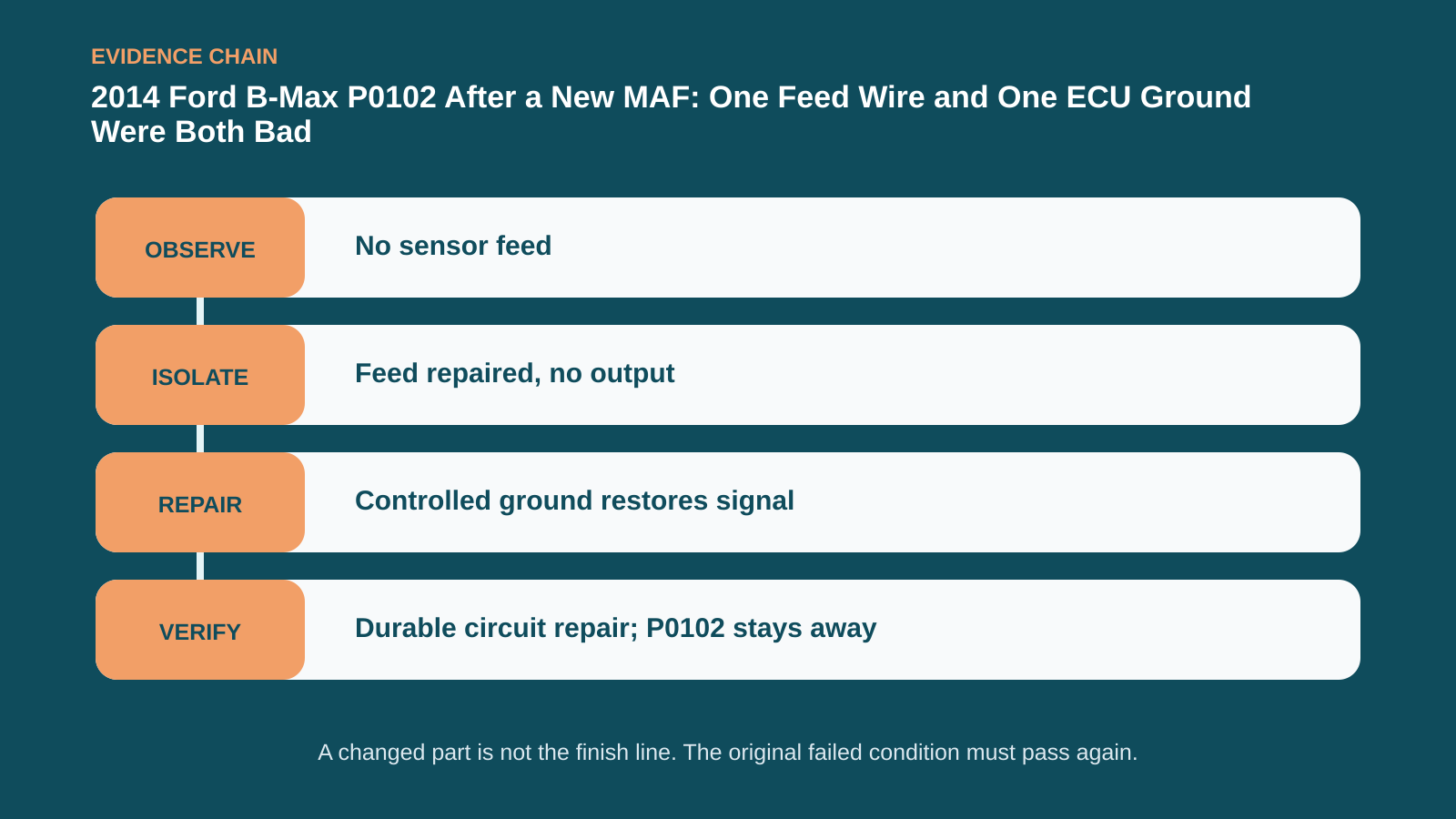
A high ground voltage can come from an open conductor, poor terminal, shared back-feed or a failed internal ECU ground driver. Load the path only according to Ford information and compare both ends. In the documented case the external wiring measured roughly 0.2 ohm, yet the ECU-supplied ground remained wrong. A temporary, fused and controlled ground restored a clean digital MAF signal. That A/B change localized the problem, but a jumper left in place without design review would not automatically be a durable or safe repair.
Prove the ECU ground path before changing it
The customer chose a sensor-earth repair instead of ECU replacement. Such a choice needs transparent documentation: which circuit was changed, how current and shared-ground effects were checked, how the joint was protected, and why programming or module replacement was declined. Use an approved splice method and keep the new path away from heat, sharp edges and high-current grounds. If manufacturer procedure requires ECU replacement, the invoice should distinguish that factory-correct route from the accepted alternative. Quietly changing architecture without a record creates the next diagnostic problem.
Complete a durable circuit repair
Verification returned to the original evidence. The digital airflow output had to respond consistently at idle and with a controlled rise in airflow; the engine had to start, idle and accelerate normally; and P0102 had to stay absent after clearing and several key cycles. Recheck voltage drop on the repaired supply and ground with the sensor loaded. Inspect fuel trims only as supporting system behavior, not as proof of one sensor. A warm road test followed by a rescan closes more of the case than an extinguished lamp in the bay.
Verify airflow, warning status and repeat starts
A later cold start is valuable because temperature and loom movement can reopen a marginal joint. Record the final pin readings and attach them to the repair order, along with the as-found and repaired wiring photos. If P0102 returns, those numbers let the next technician test change rather than repeat replacement. This B-Max was fixed by two electrical corrections in sequence. Neither result required claiming that all B-Max MAF codes share the same cause.
The new MAF was not the villain or the cure; it was a component trapped between two bad circuit conditions. Repair the supply, retest the whole path, and let the remaining evidence reveal whether the job is actually finished.










Comments 0
Questions, fixes, and real-world diagnostic notes from readers.
Be the first to share a diagnostic result or ask a follow-up question.