
Coolant Keeps Disappearing but Nothing Drips? Test the System’s Containment Boundaries

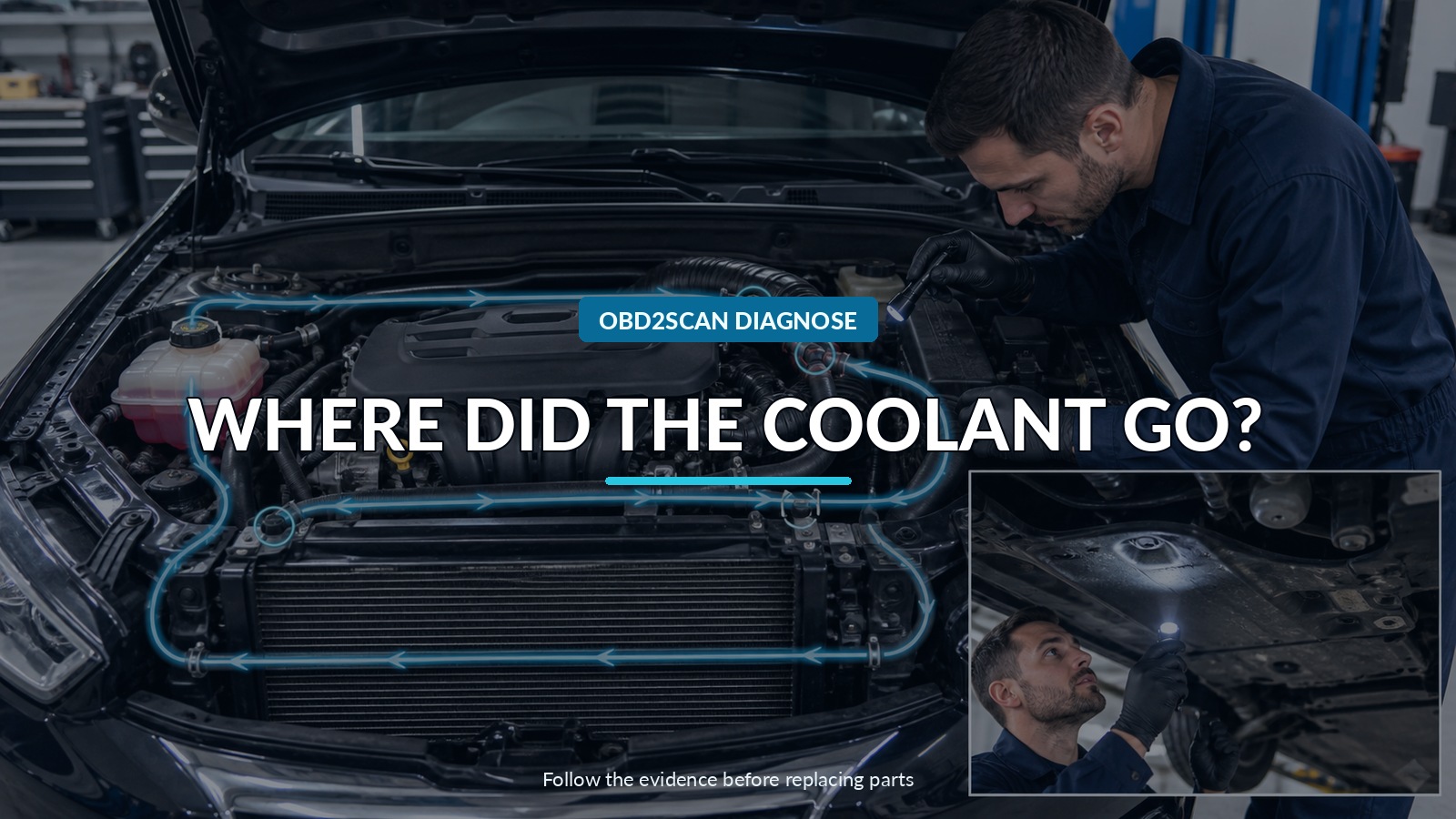
Where Did The Coolant Go?
Coolant that “disappears” without a puddle usually leaves evidence somewhere: dried residue at a cap or seam, vapor from a hot-only leak, coolant trapped in a valley or undertray, heater-core moisture, an EGR-cooler path, exhaust contamination, oil contamination, or liquid entering a cylinder. Test the cooling system as a series of containment boundaries instead of jumping from an empty reservoir to a head-gasket diagnosis.
One useful capability is controlled cold-system pressure testing followed by vacuum-assisted refill after the leak is repaired. The AUTOOL SC301 cooling-system vacuum filler and pressure tester is one route for compatible caps and adapters. It does not choose the test pressure, detect combustion gas by itself, or prove that a hot-only leak is absent.
Never open a hot pressurized cooling system. Hot coolant and steam can cause severe burns. Begin with the engine cold, use the vehicle’s specified coolant and pressure limits, and stop if liquid may have entered a cylinder because cranking can cause hydro-lock.
Quick answer: Start cold, establish a measured level-and-usage timeline, inspect every external collection point, test the cap and cooling-system boundary only to the vehicle specification, then branch into heater, EGR, exhaust, oil, and cylinder evidence.
In this guide
- Confirm that coolant is truly being lost
- Start with the cap and visible residue map
- Pressurize the cold system by specification
- Inspect external boundaries while pressure is controlled
- Branch into heater, EGR, and internal paths
- Use vacuum filling for the job it proves
- Stop for overheating or hydro-lock risk
- Verify across cold and hot cycles
Confirm that coolant is truly being lost
Set the level by the manufacturer’s cold procedure on level ground. Mark or photograph it and record mileage, date, ambient temperature, recent service, heater use, towing, and overheating. An overfilled reservoir may expel coolant and stabilize at its normal level. Air trapped after service can move into remote passages and make the reservoir fall without a continuing leak.
Verify the correct coolant mixture and appearance. Mixing incompatible coolants can create deposits that hide a level or restrict flow. Check whether the complaint refers to the pressurized expansion tank, an unpressurized overflow bottle, or the radiator itself; those systems do not move coolant in the same way.
Look for warning messages, temperature excursions, sweet odor, cabin-window film, white exhaust after warm-up, rough first start, misfires, cooling-fan faults, oil-level increase, and transmission-cooler cross-contamination. Save codes and freeze-frame before disturbing the system.
Start with the cap and visible residue map
Inspect the pressure cap cold: seals, spring, locking tabs, filler neck, vent path, and the mating surface. A cap can release early, fail to return coolant, or leak only as temperature and pressure rise. Test the cap with the exact adapter and specification where the procedure allows.
Use strong light to map dried dye or coolant residue around hose quick-connects, plastic tank seams, thermostat housings, water-pump vents, turbocharger coolant lines, heater connections, cylinder-head outlets, EGR-cooler joints, reservoir seams, radiator corners, and underbody trays. Pink, white, blue, or crusty residue can remain long after liquid evaporates.
Remove an undertray only when the vehicle is supported safely. Check the tray before cleaning it; pooled coolant can move far from the source while driving. A leak at the rear of the engine may run along a casting and drip near the transmission.
Pressurize the cold system by specification
Identify the system’s test point and rated pressure from exact service information. Gates offers testers and adapters with controlled pressure release, but tool range is not permission to use its maximum on every vehicle. Apply pressure slowly. Ford’s published cooling bulletin specifically warns that rapid pumping can create misleading behavior in its defined procedure.
Record initial pressure, coolant temperature, ambient temperature, time, and level. Hold for the specified interval while inspecting. A small gauge movement during temperature stabilization is not automatically a leak; a repeatable loss with corroborating evidence matters more.
Do not exceed the cap or system limit to “make the leak show.” Overpressure can create a new leak, damage plastic components, or push coolant into a cylinder. Release pressure through the tool’s controlled method before removing an adapter.
Inspect external boundaries while pressure is controlled
Follow the cooling circuit in order. Start at the cap and reservoir, then radiator, hoses, thermostat housing, pump, engine joints, turbo or EGR connections, heater circuit, auxiliary pumps, and any battery or charge-air coolant loop. Use mirrors, an inspection camera, clean paper, or UV dye only when compatible and approved.
Some leaks open only when materials expand, the pump turns, or combustion pressure enters the system. A cold pressure hold can pass even though the vehicle loses coolant hot. If safe, observe the warm-up with shields in place and no hands near fans or belts. An electronic pressure transducer can document pressure behavior remotely without opening the system.
Check the cabin for damp carpet, blocked HVAC drains, sweet odor, and windshield film. A heater core can leak into the case and drain outside, leaving little evidence under the hood. Pressure-test that branch only by the manufacturer method.
Branch into heater, EGR, and internal paths
If external boundaries remain dry but pressure drops, isolate subcircuits only where service information provides approved plugs or adapters. Diesel EGR coolers can leak coolant into the intake or exhaust. Ford’s published procedure for one engine family illustrates the principle: inspect external leaks first, then test the cap and a defined EGR-cooler boundary. Its pressures and steps apply only to the listed vehicles, not as a universal recipe.
For an internal engine path, inspect spark plugs and cylinders for one unusually clean, wet, or stained area; compare rather than diagnosing from one image. Check oil for level rise or emulsion, but remember that short-trip condensation can resemble contamination. Observe exhaust after full warm-up, cooling-system pressurization from a cold start, misfire data, and combustion-gas test results as a combined case.
A chemical combustion-gas tester samples gas above the coolant. It does not prove every head-gasket failure, and contaminated fluid or poor technique can mislead. A cylinder leak-down test may pressurize the cooling system if a combustion-to-coolant path exists, but exact piston position and safety procedure matter.
Use vacuum filling for the job it proves
After a confirmed repair and proper drain, a vacuum filler can reduce trapped air and draw the specified premix into a sealed system. First confirm every adapter and hose connection. A system that cannot pull or hold vacuum may have a leak in the vehicle or the setup.
Vacuum refill is not the same as a pressure test. A seal can behave differently under vacuum and positive pressure. The process also does not verify thermostat operation, pump flow, fan control, heater-valve command, combustion leakage, or correct concentration.
Follow the exact bleed, heater, auxiliary-pump, and electric-vehicle procedures after filling. Some systems require a scan-tool bleed routine or multiple reservoirs. Never assume vacuum filling eliminates all model-specific air-removal steps.
Stop for overheating or hydro-lock risk
Do not keep driving to “see where it goes” if temperature rises, the heater suddenly goes cold, the reservoir vents, the engine misfires after parking, or coolant loss accelerates. Shut down safely. An overheated aluminum engine can turn a small external leak into major distortion.
If a cylinder may contain liquid, do not crank the engine until a qualified technician has inspected and removed the liquid by an approved method. Coolant in the oil also compromises lubrication. Tow the vehicle rather than using the remaining coolant as a travel budget.
Professional routes from Gates, Stant, Mityvac, OEM tool programs, and specialist adapters may fit different caps and circuits. SC301 earns its place when one tool must support both controlled pressure evidence and vacuum refill across verified adapters. The vehicle, not the kit, defines the limit.
Verify across cold and hot cycles
After repair, clean old residue so new evidence is visible. Pressure-test the cold system and cap by specification, refill and bleed correctly, confirm heater output and fan operation, and inspect all disturbed joints. Save a new cold level reference.
Repeat the drive and heat-soak that produced the loss, then allow a complete cool-down before rechecking. Confirm stable level across more than one cycle when the complaint was slow. Check oil, exhaust, misfire data, undertray, cabin, and external residue as appropriate.
The final record should name the boundary that failed and the evidence that now holds. “Added coolant and no puddle” is not verification. A controlled cold hold, correct hot operation, dry inspection, and stable cold level close the case far more convincingly.









Comments 0
Questions, fixes, and real-world diagnostic notes from readers.
Be the first to share a diagnostic result or ask a follow-up question.