Crankshaft-Sensor Code Appears Only Hot? Capture the Signal During the Stall

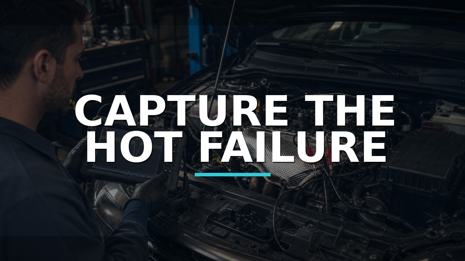
Capture The Hot Failure
A cold resistance reading cannot testify about the instant a hot crank signal disappears. Heat changes semiconductor behavior, coil resistance, connector tension, insulation, and harness movement. If the engine stalls or will not restart only after heat soak, capture the signal during that exact event before the vehicle cools and the evidence returns to normal.
A compact meter with a basic scope can bridge static checks and an event waveform. The AUTOOL DM303 automotive multimeter and handheld oscilloscope is one route for capturing a low-frequency crank signal or supply dropout in the field. A multi-channel automotive scope is stronger when cam/crank correlation, simultaneous supply and signal, long memory, or intermittent capture depth matters.
Identify the sensor type and exact pinout before connecting. An ohmmeter test on an unknown Hall sensor can mislead or cause damage. Keep back-probes secure and all leads away from exhaust, belts, fans, and the starter path.
Quick answer: A cold resistance check cannot clear a heat-only fault. Save code and stall context, inspect the circuit, secure rated leads away from moving parts, capture the crank signal through warm-up and heat soak, and compare the dropout with power, ground and engine-speed evidence.
In this guide
- Preserve the hot-failure sequence
- Identify inductive, Hall, or other sensor architecture
- Compare ECU RPM with the physical symptom
- Verify supply, ground, and connector integrity
- Capture the waveform through heat soak
- Separate sensor, target wheel, wiring, and controller branches
- Choose enough scope for the signal
- Prove hot restart after repair
Preserve the hot-failure sequence
Record the exact DTC, status, freeze frame, rpm at stall, coolant and intake temperature, battery voltage, run time, ambient condition, and restart behavior. Did the tachometer drop instantly while the engine was still rotating? Did injector pulse or ignition disappear? Did the engine cut cleanly or lose power gradually? How long must it cool before restarting?
Do not clear the code or unplug the sensor immediately. That can cool or reseat the connection. Scan all modules for voltage and communication events that could imitate an engine-speed-signal loss. Note recent timing, transmission, starter, engine, or harness work.
Create a heat timeline: cold start, warm-up, first symptom, failed restart, recovery. Place every measurement on it. A component tested five minutes after the stall may already be outside the failure state.
Identify inductive, Hall, or other sensor architecture
Use service information to identify sensor technology, pin count, supply, ground, signal, air gap, target wheel, and expected waveform. A two-wire inductive sensor generates an AC-like signal whose amplitude changes with speed and gap. A three-wire Hall sensor commonly requires supply and ground and switches a digital signal. Other magnetoresistive or encoded designs require their own method.
This distinction controls the tool setup. Resistance may be relevant to an inductive coil if the manufacturer specifies it. It is not a universal health check. Hall sensors need supply and ground testing and waveform observation. Connecting a low-impedance test lamp or powered probe to a signal can damage the sensor or controller.
Confirm whether the sensor is crankshaft or camshaft and how the ECU uses redundancy. Some engines continue running with one missing signal but will not restart; others stop immediately. That behavior shapes the capture plan.
Compare ECU RPM with the physical symptom
Watch cranking rpm in scan data during both a good cold start and failed hot restart. Zero rpm while the engine physically cranks supports a missing or unrecognized position signal, but does not identify sensor versus circuit, target, cranking speed, or ECU. A plausible rpm display does not prove waveform quality; the ECU may briefly calculate from another input.
Compare injector command, ignition command, synchronization status, immobilizer state, and battery voltage if available. A slow hot starter or voltage collapse can lower an inductive signal and set a sensor code as a consequence. A lost main relay or ECU ground can erase rpm along with many other parameters.
Use a current clamp or voltage record to confirm actual cranking behavior if needed. Keep “the engine turns” separate from “it turns at adequate, stable speed.”
Verify supply, ground, and connector integrity
For a powered sensor, back-probe supply and ground with the circuit assembled where possible. Measure during cold operation, heat soak, stall, and failed restart. A stable signal cannot exist if supply or ground disappears. Use voltage-drop measurements under operating load rather than relying only on resistance with the circuit off.
Inspect oil intrusion, terminal tension, corrosion, heat-hardened insulation, shielding, routing, and clearance to the exhaust or rotating target. Gently move one harness area while watching the signal. Avoid pulling on the sensor lead, which can create an internal open not present before.
For an inductive sensor, inspect resistance only by the specified disconnected method and compare cold versus immediate hot failure if safe. An in-range value does not prove amplitude, gap, shielding, or intermittent continuity under vibration.
Capture the waveform through heat soak
Connect at the least intrusive valid point, verify the scope ground strategy, and choose voltage range, coupling, time base, and trigger for the sensor type. Save a known-good cold waveform at cranking and idle with rpm. Then maintain the same connection through the controlled heat cycle so the act of reconnecting does not disturb the fault.
Observe amplitude, switching levels, period, missing-tooth reference, noise, dropout, and relationship to engine speed. When the stall occurs, capture before and after. A single-channel DM303 can answer “did this signal disappear or deform?” For “did cam timing shift relative to crank while both supplies stayed good?” use a multi-channel scope such as PicoScope 4425A, Autel MaxiScope, Micsig ATO, or another tool with suitable memory and probes.
Do not compare two screenshots with different scales as though they were identical tests. Label sensor, test point, engine speed, temperature, voltage scale, time base, and probe type.
Separate sensor, target wheel, wiring, and controller branches
If supply and ground remain stable while the signal disappears at the sensor during the hot failure, the sensor or its air gap/target interaction becomes stronger. If the signal is good at the sensor but bad at the ECU pin, inspect wiring, shielding, connectors, and cross-talk. If it reaches the ECU cleanly but scan rpm vanishes, verify ECU powers, grounds, and known processing conditions before considering the controller.
A deformed repeating waveform may reflect target-wheel damage, excessive runout, debris, air-gap change, or mechanical movement. A low-amplitude inductive signal can reflect slow cranking or excessive gap. Random noise may arise from routing, shielding, ignition interference, or poor scope grounding.
Codes are often consequence records. A stalled engine naturally stops producing crank pulses. Use the pre-stall section of the capture to determine whether signal loss led the stall or merely followed it.
Choose enough scope for the signal
PicoScope 4425A, Autel MaxiScope, Micsig ATO, Snap-on diagnostic platforms, and Fluke ScopeMeter routes offer different combinations of channels, memory, guidance, ruggedness, and ecosystem support. DM303 occupies a compact combined meter/scope role for basic single-signal capture and conventional circuit checks. No defensible public model-level share dataset ranks them for this niche.
Choose by bandwidth with margin, sample rate, memory depth, number of simultaneous channels, automotive attenuators and current clamps, trigger/logging capability, input protection, and training. A 500 kHz-class handheld can be entirely adequate for a low-frequency crank dropout yet frustrating for long multi-channel captures. Buy the evidence depth the recurring job requires.
Prove hot restart after repair
Repair the proven sensor, terminal, harness, shield, target, supply, ground, starter, or mechanical issue. Route and clip wiring exactly, restore heat shields and seals, clear saved faults, and retain the before waveform.
Repeat the full heat timeline until the engine is at the state that caused the stall. Confirm waveform shape and amplitude at the same test point and scale, stable supply/ground, continuous scan rpm, normal synchronization, no stall, and prompt hot restart. Repeat after a soak of the original duration.
The closing evidence should show sequence: the crank signal failed before engine speed reached zero while supply and ground remained; the repair removed that dropout through the same heat cycle; and hot restart returned. That is how a waveform turns a temperature-sensitive code into a bounded diagnosis.