
Vespa Scanner Will Not Connect? Solve the Connector–Power–Coverage Handshake

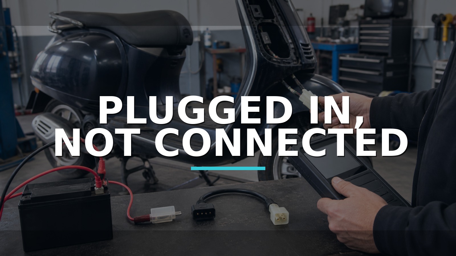
Plugged In, Not Connected
The adapter is only the middle of a three-party handshake. The scooter must present the expected connector and electrical path; the cable must be the correct variant and intact; the scanner must contain the right model, ECU, region, and protocol coverage. A plug that physically fits can still leave all three parties silent.
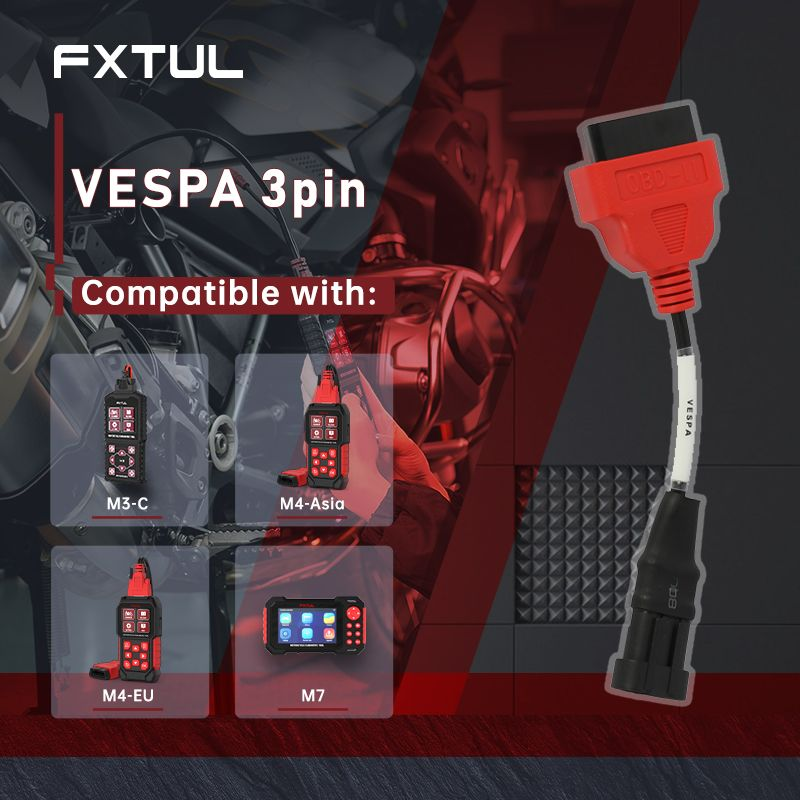
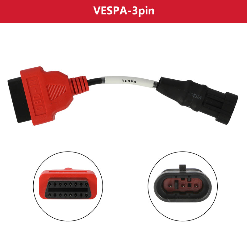
Once the scooter connector and scanner coverage are confirmed, the remaining hardware question is whether the adapter maps that exact bike-side connection to the scanner family already owned. For users of the listed M3-C, M4-EU, M4-Asia, or M7 variants, the FXTUL Vespa 3-pin diagnostic cable is one exact-family adapter route; select the option that matches the scanner actually in hand. A passive cable can complete a compatible physical path, but it cannot add a missing protocol, ECU, software license, or service function.
Do not assume pin function from connector shape, and never add external power until the exact cable/scanner instructions identify the path and polarity. This compact checkpoint guide lets the bike, cable, and software answer one question at a time.
Quick answer: A passive adapter is only the middle of the handshake. Identify the exact scooter and connector, match the cable option to the scanner family, prove any documented auxiliary power path, select the exact ECU/function, and separate cable integrity from software coverage.
In this guide
Name all three sides of the handshake
Record manufacturer, model, model year, market, engine size/code, VIN, ECU identifiers if known, and the system you want to access. Vespa/Piaggio families span generations, connectors, engine controllers, ABS systems, and regional variants. A seller’s broad model name is discovery information, not proof that one cable and menu covers every revision.
Locate the diagnostic connector using the vehicle manual/service information. Photograph its housing, wire count, colors, keying, cap, and nearby harness before connection. Similar three-pin shells can be used differently. Check for corrosion, pushed terminals, previous repairs, missing caps, and aftermarket alarms or ECUs. Do not bridge or probe pins from color assumptions.
| Handshake party | Must agree on | Typical failure |
|---|---|---|
| Scooter | Connector, power/ground/data, awake ECU | Wrong port, fuse, battery, wiring, ECU state |
| Cable | Scanner-end variant, pin mapping, integrity | Wrong M4/M7 variant, damage, poor terminal fit |
| Scanner/software | Model, region, ECU, protocol, function | Missing/outdated coverage or wrong menu |
Confirm the exact bike and connector
Read the scanner model and regional version from the device/system screen and label, not memory. Match it to the exact option on the FXTUL cable page. M4 Asia and M4 EU are not interchangeable names, and an M7 variant can use a different scanner-side arrangement. Compare the received cable with current first-party photos and labeling before inserting it.
Inspect both ends for bent/recessed pins, damaged seals, loose strain relief, contamination, and non-factory splices. Confirm the scooter connector key aligns without force. A tight wrong fit can spread terminals and create a new intermittent fault. If the cable includes or requires an auxiliary power path, use only the documented lead and sequence.
Inspect keying and pin condition
Check battery condition and terminal security. Small scooter batteries can fall sharply during key-on, cranking, or pump operation, resetting the scanner or ECU. Use the service procedure and correct battery chemistry; do not infer the scooter’s acceptable voltage from the scanner’s input specification. Verify relevant fuses and grounds electrically.
Some adapter arrangements need a separate battery connection to power the diagnostic interface. Identify positive and negative from the cable instructions and connect in the stated order, with ignition state as directed. Reverse polarity or improvised clips can damage the scanner, cable, or ECU. If documentation is missing, stop instead of experimenting.
Prove the required power path
With the correct connection, observe whether the scanner powers, whether its status changes at key-on, and whether any system is reachable. Listen for normal pump/relay activity without treating sound as proof. Check immobilizer behavior and warning lamps. An ECU that is not awake because of kill switch, side-stand logic, fuse, ground, or low voltage cannot complete the handshake.
Do not crank repeatedly merely to wake diagnostics. Many procedures require key on/engine off; others specify a run state. Follow the exact model instructions. If the scooter has been modified with an aftermarket ECU or immobilizer, original coverage may not apply even when the connector remains unchanged.
Match the cable variant to the scanner
Update the scanner by its documented method and verify date/version. Navigate by exact brand, model, year/engine, and system rather than selecting a visually similar scooter. Try automatic identification only if supported, then use manual selection where instructed. Record “not supported,” “link error,” “ECU not found,” and power errors separately; generic wording can represent different stages.
Coverage has layers. A model listing may mean engine codes but not ABS, service resets, data, or actuators. A cable listing confirms physical compatibility with a scanner family, not those functions. Check the current coverage list or obtain written confirmation for the specific ECU/function. If support requests a log, provide the model identifiers and original error without clearing or editing it.
Try model and system selection deliberately
With the cable disconnected from vehicle and scanner, continuity can verify end-to-end conductors only when the first-party pin map identifies corresponding terminals. Check for shorts between conductors and intermittent opens while gently flexing the strain relief. Do not use resistance measurements through a powered ECU or scanner. A continuity pass does not prove correct mapping or terminal contact under connection.
If no reliable pin map is available, compare with a known-good exact cable or use authorized support. Do not reverse-engineer by applying voltage. A passive adapter changes connector format; an incorrectly mapped copy can place power on data. The low price band of a cable never justifies the high replacement cost of a controller.
| Result | Strong next step |
|---|---|
| Scanner unpowered | Verify documented auxiliary power, battery, cable variant |
| Scanner powered, all ECUs absent | Key state, data path, coverage, cable mapping |
| Engine connects, ABS absent | Function/ECU coverage and ABS connector/path |
| Connection changes when cable moves | Terminal fit or conductor strain diagnosis |
Separate cable failure from coverage failure
This is the most common handshake confusion. A three-pin plug can seat perfectly while the scanner lacks the selected ECU protocol. Conversely, coverage may exist but a wrong adapter variant routes it incorrectly. Test each agreement independently: correct vehicle connector by service information; exact cable variant by first-party record; exact model/system/function by current software list.
Do not buy a chain of random adapters hoping one will unlock service functions. Every added junction introduces contact resistance and mapping uncertainty. If an OEM cable or scanner route is required, use it. If the desired function involves immobilizer programming, ABS bleeding, or safety-critical coding, confirm authorization and recovery procedures before connection.
Compare adapter ecosystems
There is no defensible public model-level market-share dataset for this adapter niche. TEXA Bike and Jaltest Bike provide professional multi-brand ecosystems; Piaggio dealer systems provide the controlling manufacturer route; OBDSTAR and other motorcycle scanners offer differing coverage; generic ELM-style interfaces can be useful only where exact protocol/software support is proven. Dedicated owner communities may document combinations, but current first-party coverage should decide a commercial purchase.
| Route | Best fit | Tradeoff |
|---|---|---|
| Exact FXTUL cable plus supported scanner | Existing M3/M4/M7 owner with confirmed vehicle/function | Cable adds no missing software |
| Professional multi-brand bike platform | High-volume shop, broad coverage, support | Higher equipment/update band |
| OEM/dealer route | Deep procedures, programming, recovery | Access and cost constraints |
| Generic interface/app | Bounded owner data on explicitly supported models | Variable hardware/software/security |
| Outsource/no-buy | One rare scooter or advanced function | Often safest complete solution |
If current scanner coverage already names the Vespa/Piaggio model, ECU, and required function but the bike uses a different diagnostic connector, an exact-family adapter cable can complete the physical path. The FXTUL Vespa cable serves that role for the scanner variants listed on its current page; match the product option to the hardware and region actually owned, then verify any required auxiliary power before connection.
If coverage is absent, another cable will not solve the handshake. A TEXA or Jaltest platform is the stronger route for a workshop that needs broad guided coverage and support, while OEM/dealer tooling controls deep procedures, programming, and recovery. For one rare scooter or an advanced function, outsourcing may be the lowest-risk complete method. The useful accessory is the verified final link in an already compatible chain.
Build a compatibility passport before buying
Write five fields: scanner hardware family/region, software version, scooter VIN/model/year/engine, target ECU, and required function. Send that exact passport to the seller or manufacturer when the public list is ambiguous. Save the response and product-option name. “Works with Vespa” is not a compatibility answer; “connects to this engine ECU for codes/live data using this M4 Asia cable variant” is much closer.
Include update method and support path in the purchase decision. A low-cost adapter with no verifiable mapping or support can be more expensive than an exact first-party cable after one failed job. For a professional shop, keep passports for recurring scooter families and label cables by scanner side to prevent mix-ups.
Diagnose auxiliary power as its own branch
Where the official adapter requires battery clips or another feed, inspect clip polarity labels, fuse/protection, conductor strain, and connection sequence. Measure the scooter battery at the posts before connection. If the scanner resets when the key turns on, observe battery behavior and adapter feed using safe passive measurement. Do not replace the cable merely because a weak battery cannot sustain the handshake.
Never borrow power from an unrelated connector or generic USB source. The diagnostic interface may expect common ground and a protected vehicle supply. Improvised power can create ground loops, reverse polarity, or battery-positive contact on a data conductor.
Handle “engine works, ABS does not” correctly
Partial communication proves that some of the chain works. It does not prove the same cable pins, connector, gateway, or software cover the ABS ECU. Check whether ABS uses the same diagnostic connector and whether the purchased scanner/function list names it. Save the engine connection success and ABS error separately.
If an advanced service action is available, confirm prerequisites before pressing it. ABS bleeding, immobilizer, throttle learning, and coding can change vehicle state. Reading a code is low consequence; commanding a procedure is a separate authorization and coverage decision.
Protect the connector after the job
Replace the dust cap, route the harness away from heat and steering movement, and do not leave the adapter fitted. Moisture and spread terminals can convert a one-time service into intermittent communication later. Inspect both ends before storage and keep variant labels readable.
Save logs and verify reconnection
Once the failed agreement is corrected, connect without force in the documented order, stabilize the scooter, select the exact software path, and save a full scan. Confirm module identity and expected data before clearing codes or attempting a service function. If an auxiliary lead was used, disconnect in the prescribed sequence and replace the diagnostic cap.
Reproduce the original condition: cold key-on, post-battery-work, engine communication, or requested ABS/service access. Check that cable movement no longer affects connection and that the battery remains stable. The closing record should state which party failed—vehicle power/path, cable variant/integrity, or scanner coverage. “It plugs in now” is not a completed handshake; reliable communication with the intended ECU is.
Handshake disputes
The cable listing names my scooter—why verify the scanner variant? The product page offers separate scanner-family options. Scooter-side fit can be identical while scanner-side mapping or connector differs. Both ends of the cable must match.
Can an adapter update add missing ABS coverage? No. A passive cable has no software database or license. Update/coverage comes from the scanner platform. The adapter only routes documented electrical paths.
Should I buy a generic three-pin cable to test the theory? Only when its mapping, polarity, power method, scanner compatibility, and vehicle application are documented. Physical resemblance is insufficient and a wrongly mapped low-cost cable can expose expensive electronics to the wrong voltage.
A five-minute handshake card
- Write the exact scooter, ECU/system, scanner family/region, software version, and desired function.
- Match the purchased FXTUL option to the scanner—not merely the scooter connector.
- Identify the vehicle diagnostic port and pin functions from trusted service information.
- Inspect scooter connector and both cable ends before inserting anything.
- Stabilize the battery and connect any documented auxiliary feed with correct polarity/sequence.
- Choose the exact software menu and save the error wording or successful module ID.
- If one party still disagrees, test only that branch or send the compatibility passport to support.
The card should travel with the cable. It prevents another technician from using an M4 Asia-labeled lead on an M7, or from assuming a cable that reads the engine must support ABS service. Add a known-good confirmation only when the second scooter/scanner combination is itself documented; otherwise two unknown systems do not form a control.
Keep the resulting compatibility record with the scooter’s service history.
Decision rule: Purchase the cable only after scooter, scanner variant, and required function all have documented matches. During diagnosis, change one party at a time. A confirmed bike and scanner isolate the cable; a confirmed cable and bike isolate coverage; a known-good scanner/cable isolates the scooter path. Without two known parties, the handshake remains ambiguous.






Comments 0
Questions, fixes, and real-world diagnostic notes from readers.
Be the first to share a diagnostic result or ask a follow-up question.