
How to Use the AUTOOL CT200 Fuel Injector Cleaner and Tester

The AUTOOL CT200 fuel injector cleaner and tester is a six-position bench for compatible removed standard 12 V gasoline port injectors. It uses one liquid in the ultrasonic-cleaning tank and a different liquid in the pressurized test circuit. Keep those circuits separate, use the settings and limits for the exact injector, and never loosen a rail, plug, injector, hose, fitting or drain until the pressure gauge is stably at zero.
This guide follows the current CT200 layout with electronic Increase Pressure and Decrease Pressure buttons. Before operating, match the actual machine’s 110 V or 220 V nameplate to the supply and compare its panel, accessories and labels with its exact manual. If your delivered unit has different pressure controls or fittings, stop and use the instructions for that revision.
Last reviewed: August 28, 2026.
In this guide
- The CT200 workflow at a glance
- What the CT200 can show—and what it cannot prove
- Before you start
- Know the machine and keep the circuits separate
- Phase A: qualify and inspect the job
- Phase B: ultrasonically clean the injectors
- Phase C: mount and test under containment
- Phase D: return the machine to a safe state
- How to interpret the result
- CT200 troubleshooting and stop rules
- Frequently asked questions
- The real result is a repeatable comparison and a safe closeout
The CT200 workflow at a glance
One controlled job has four phases:
- Qualify the job. Identify and label the injectors, obtain their service data, match the CT200 mains version and inspect the machine, glass cylinders, rail, hoses, plugs, seals and leads.
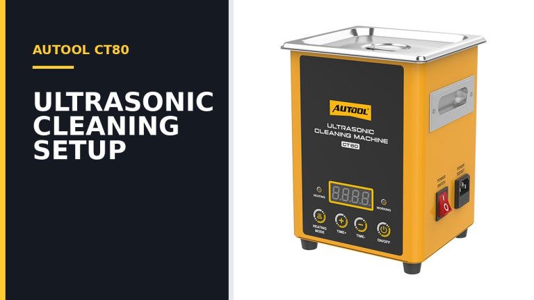
- Ultrasonically clean. Put approved cleaning fluid in the rear tank, support only the permitted injector area on the supplied bracket, keep electrical connections dry, select
01 Ultrasonic Cleaningand run an evidence-based interval without heat. - Test under containment. Install compatible top-feed injectors squarely, close every unused position with the intended plug, add approved test fluid to its own circuit and use injector-specific conditions for leakage, spray and volume comparisons.
- Close at zero pressure. Press
Stop, useDecrease Pressureuntil the gauge is stable at zero, then switch off and unplug before disconnecting or draining anything on the pressure side. Recover the two liquids separately.
Stop for a leak, moving injector or rail, cracked or shifting glass, unstable pressure, fluid near electrical parts, abnormal pump or ultrasonic sound, unusual heat, smoke, odor, a hot cable, or a control/display fault. If the gauge will not reach and hold zero, leave the pressure system assembled and obtain qualified service.
What the CT200 can show—and what it cannot prove
The CT200 can operate several compatible injectors under the same commanded conditions so you can observe nozzle leakage, compare spray behavior and compare collected volume. A before-and-after test can show whether a repeatable imbalance changed after cleaning.
Those observations are not a complete injector or vehicle diagnosis. The panel’s simulated speed modes do not measure actual engine RPM. A visually improved spray does not prove correct electrical behavior, calibrated delivery or safe on-vehicle operation. A low cylinder level can come from the injector, but it can also come from a seal, adapter, rail, channel or test-condition problem.
Keep the comparison controlled. Use the same injector-to-channel assignments, test fluid, pressure, pulse setting, mode, time or injection count, mounting and cylinder starting condition. Judge the result against the exact injector or vehicle service limits, not a generic percentage or a picture of an ideal spray.
Before you start
Confirm that the injector belongs on this bench
The detailed procedure below is for compatible top-feed standard gasoline port injectors after they have been removed from the vehicle. Before connecting one, obtain its part number and confirm:
- feed style, physical length and required upper/lower adapters;
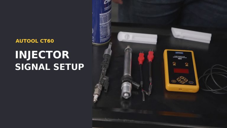
- connector, polarity and electrical resistance or current class;
- surfaces that may contact ultrasonic fluid and any parts that must remain dry;
- approved seals, filter/cap handling and assembly lubricant;
- cleaning-fluid compatibility and exposure limit;
- test pressure, pulse width, time or injection count, and leakage/flow acceptance limits.
Do not apply this procedure to GDI, FSI or another high-pressure direct injector. Do not use it for diesel injectors. Low-impedance, side-feed or special-length injectors also need explicit CT200 support and their exact adapter and electrical instructions; a connector that happens to fit is not proof of compatibility.
If a safe before-cleaning baseline is possible, label every injector by vehicle cylinder and record leakage, spray and volume under the same conditions you will use later. If contamination, damaged seals or an uncertain setup makes a baseline unsafe, skip the baseline and clean first.
Match the exact CT200 and manual
Treat 110 V and 220 V as separate versions. Read the actual nameplate, confirm an intact protective-earth connection and use a correctly grounded supply that matches the marked voltage and plug. Do not assume the machine changes voltage automatically.
Use the AUTOOL manual download center to select CT200, then match the document to the panel, pressure controls and accessories in front of you. A generic CT-series instruction or a different CT200 revision cannot override the delivered unit’s labels.
Prepare the work area and PPE
Place the CT200 upright on a dry, level, stable and well-lit bench in a ventilated area. Keep cigarettes, flames, sparks, heaters, grinding and hot work away. Route the cord and injector leads so they cannot pull an injector sideways or contact liquid, heat or a sharp edge.
Wear splash goggles and gloves selected from the current safety data sheets for both liquids. Keep compatible spill-control material and labelled recovery containers ready. Do not leave the machine operating unattended.
Use two purpose-approved liquids
The circuits are not interchangeable:
- Ultrasonic cleaning fluid goes only in the rear cleaning tank. Use a purpose-made injector or engine-carbon cleaning fluid approved for ultrasonic use and compatible with the injector, seals and machine materials.
- Injector test fluid goes only in the test-fluid circuit. Use a purpose-made, non-corrosive fluid approved for the CT200 pump, hoses, seals and the injector.
Follow each product’s SDS for ventilation, glove material, spill response, storage and disposal. Do not use gasoline, kerosene, alcohol or an improvised/corrosive liquid in this workflow. Never cross-fill the circuits, and never run the ultrasonic tank dry.
Know the machine and keep the circuits separate
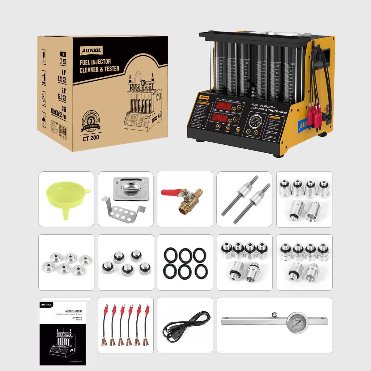
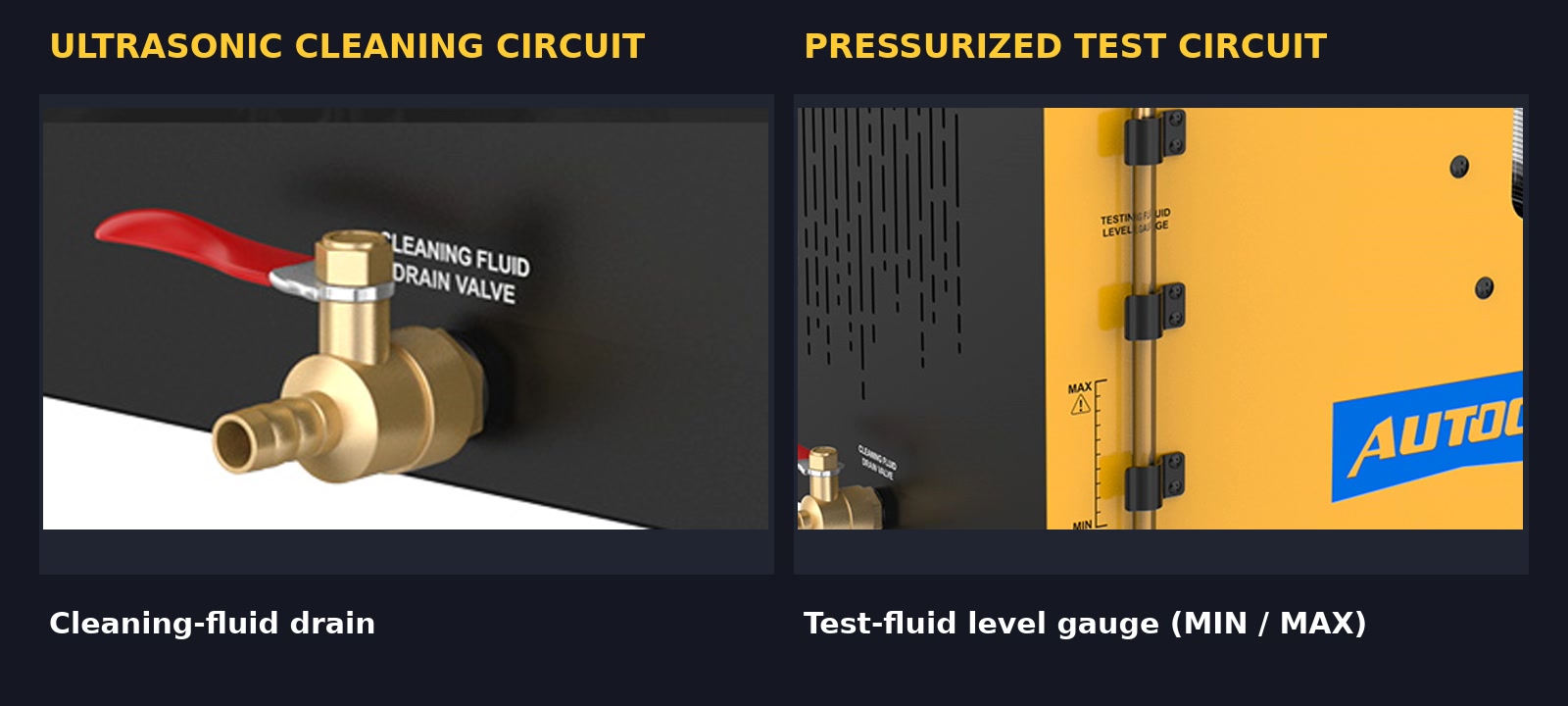
The current-style CT200 has six glass measuring cylinders and their front drains, a top rail and pressure gauge, an ultrasonic tank and cleaning-fluid drain at the rear, and a separate test-fluid fill/level/recovery system. The side test-fluid gauge has a marked operating zone. The side rocker is the mains power switch; this workflow does not use a second ultrasonic switch or any heating control.
The front panel shows the function/pulse display, the time/injection-count display, Start, Pause, Stop, and pressure increase/decrease controls. Labels for some simulated-speed and spray-volume modes can vary slightly by revision, so follow the labels printed on your panel.
Phase A: qualify and inspect the job
Step 1: Identify and label every injector
Relieve vehicle fuel pressure and remove the rail and injectors only under the vehicle maker’s service procedure. Protect open vehicle lines, then assign each injector a durable cylinder label. Record the part number, connector and feed style before cleaning removes any useful exterior evidence.
Remove loose exterior contamination by a method approved for that injector and away from the CT200. Inspect the body, inlet, nozzle, connector and sealing lands. Replace a cut, hardened, swollen, loose or missing seal with the exact compatible part before any pressure test. Do not remove a filter, cap or other small component unless the injector instructions explicitly require it.
Completion check: Each injector remains traceable to its vehicle position, its compatibility and service values are known, and its pressure-sealing parts are serviceable.
Step 2: Inspect the CT200 and set up the bench
With the side switch off and the plug disconnected, inspect:
- the power cord, plug, socket, protective-earth condition, case and readable nameplate;
- all six glass cylinders, mounts and front drains for cracks, chips, looseness or binding;
- the rail, gauge, outlet hose, fittings, locking rods and upper plate;
- the correct adapters, intended unused-position plugs, O-rings and seals;
- injector signal leads, connector adapters and the cable-storage hook;
- the ultrasonic tank, bracket and cleaning-fluid drain;
- the test-fluid fill path, side level gauge and recovery route.
Keep the unit out of service for damaged glass, an unreadable or unstable gauge, a binding drain, loose cylinder, damaged/swollen hose or seal, leaking fitting, damaged cord/earth, wet electrical area, missing correct adapter/plug, or a display/control fault.
Completion check: The dry machine is stable and intact, power can be disconnected quickly and safely, and every required fitting closes without force.
Step 3: Stage and label the two liquids
Keep the cleaning fluid, test fluid and their recovery containers physically separated. Confirm each label and SDS before opening either container. Close the cleaning-fluid drain and test-fluid recovery route in the operating position specified for your unit, then recheck that each route is dry and serviceable.
Do not use an advertised capacity or a quantity from another manual revision as a fill instruction. Follow the marks on your unit and the exact fluid and machine instructions.
Completion check: Each liquid and recovery container has one identified circuit, and no fluid has entered the machine yet.
Phase B: ultrasonically clean the injectors
Step 4: Prepare the supported cleaning arrangement
Keep the CT200 unplugged. Place the supplied perforated bracket in the ultrasonic tank. Position each compatible injector so only the surfaces approved by its instructions enter the fluid and all electrical connectors and lead connections remain above it. Use the correct pulse/drive connector without forcing it; special injectors require their approved adapter lead.
Add the approved cleaning fluid slowly while accounting for injector displacement. Follow the marks on your tank or the exact instructions, keep the machine exterior and electrical areas dry, and do not overflow or start an empty tank. There is no universal immersion depth: follow the injector maker’s immersion limit.
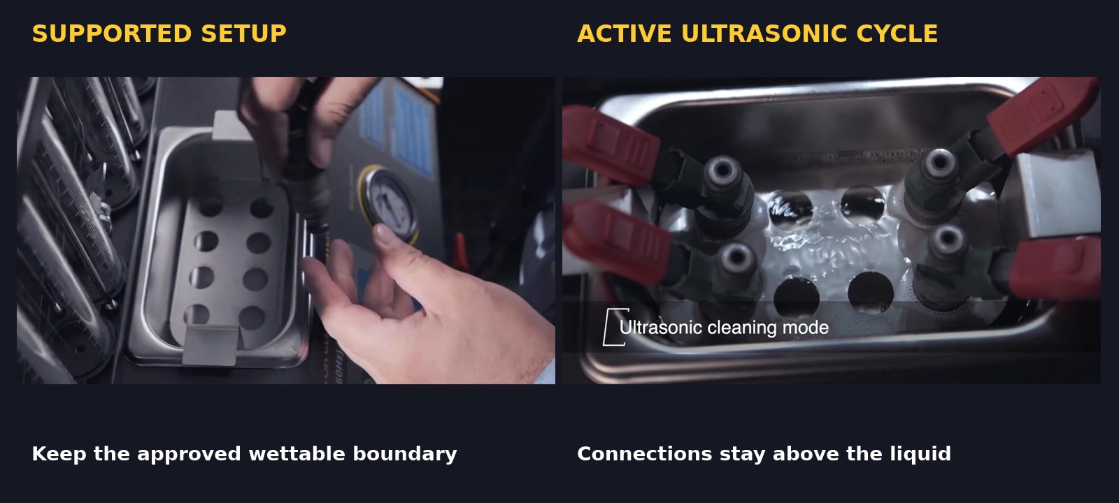
Completion check: The bracket and injectors are stable, every electrical connection is dry, the approved fluid follows the marks or exact instructions, and the tank is not dry or overfilled.
Step 5: Select menu 01 and run an evidence-based cycle
Dry your hands and the work area. Recheck the nameplate and matching supply, connect power and turn on the single side mains switch. On the front panel, select 01 Ultrasonic Cleaning, set the interval specified for the injector and cleaning fluid, then press Start.
Do not copy a value from a demonstration, a generic manual or the end of the machine’s time range. This CT200 workflow uses no heat. Do not look for a heating switch or a second side ultrasonic switch.
Stay with the machine. Watch injector stability, liquid containment, leads, cord and display without touching the bath. Press Stop for overflow, leakage, movement, abnormal vibration or sound, unusual heat, smoke, odor, hot wiring, fluid near an electrical area or a control fault. Isolate power at a safe point if an electrical event makes the front controls unsafe to approach.
Completion check: The selected cycle ends normally with the injectors still supported, connections dry and fluid contained.
Step 6: Stop, remove, dry and inspect
Press Stop, switch off and unplug before touching the leads, bracket or injector. Remove the supported parts without carrying liquid over the front panel, switch or socket. Recover cleaning fluid only through the intended cleaning-circuit route and into its labelled container; follow the fluid instructions before filtering, reusing or disposing of it.
Complete any injector-specific rinse or drying step. Inspect the connector, body, sealing lands and installed seals again. Apply only a small amount of lubricant expressly approved for the exact seal, injector and test fluid when assembly instructions call for it.
Completion check: The injectors are dry where required, their seals and adapters are ready for pressure, and cleaning fluid has not entered the test circuit.
Phase C: mount and test under containment
Step 7: Install compatible top-feed injectors squarely
Keep the machine stopped and unpressurized. Match the exact inlet connector/adapter to each top-feed injector. Seat the injectors straight, place the upper rail squarely across the set, and tighten the locking rods or nuts evenly enough to seal without tilting an injector or side-loading a glass cylinder. Do not guess a torque value; use one only when it is specified for the exact assembly.
If testing fewer than six injectors, close every unused rail position with the intended supplied plug and an intact compatible seal. One injector requires five correctly sealed unused positions. Connect the outlet hose and signal leads only after the mechanical assembly sits squarely; route them so they do not pull on the rail.
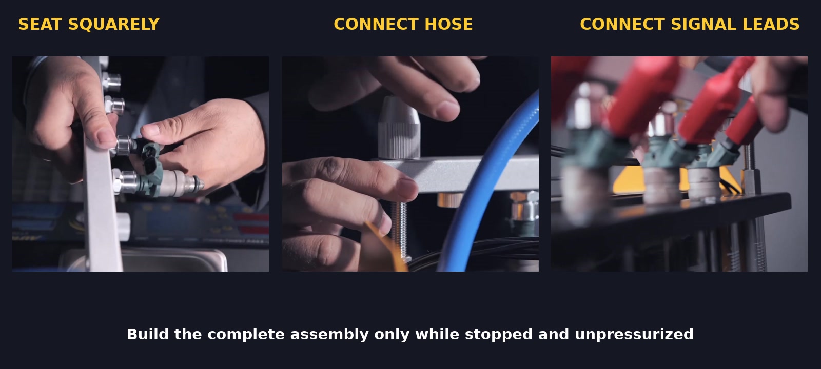
Completion check: Injectors are identified, vertical and evenly seated; the rail is square; all used and unused positions are sealed; leads and hose are secure without side load.
Stop: Do not pressurize a crooked injector, mismatched adapter, damaged seal, improvised plug, binding rail or displaced glass cylinder.
Step 8: Add approved test fluid to its circuit
Verify that the pressure gauge reads zero and the machine remains switched off and unplugged. Add the approved injector test fluid slowly through the designated test-fluid fill path. Use the side level gauge on the delivered CT200 and keep the fluid within its marked operating zone without exceeding MAX.
Do not fill a measuring cylinder as a setup target and do not use a quantity from another manual revision. Clean up any spill according to the fluid instructions before connecting power, and keep all electrical areas dry.
Completion check: The test-fluid gauge is within the delivered operating marks, its fill path is closed, and every external joint remains dry.
Step 9: Establish pressure gradually and prove containment
Recheck the injector’s specified test pressure and the limits of every adapter, seal and fitting. Power the machine, select the mode required by the service procedure using the label on your panel, then begin at zero and use Increase Pressure gradually while standing outside the rail, glass and spray area.
Watch the gauge and every hose, rail, adapter, plug, seal, drain and cylinder connection before proceeding. The machine’s maximum capability is not a default test setting. Use only the condition prescribed for the exact injector and never exceed the lowest limit for the injector, adapter, seal, hose or machine.
For seepage, movement, unstable pressure, abnormal pump sound or liquid outside the intended path, press Stop and use Decrease Pressure until the gauge is stably at zero. Do not tighten, reseat or touch a pressurized part.
Completion check: The required pressure is stable, the assembly remains square and dry externally, and the operator stays outside the pressure/spray boundary.
Step 10: Run the leakage observation
Use the leakage mode printed on the delivered panel. Keep the exact injector-approved pressure, pulse state and observation interval recorded; do not copy a generic manual time or pressure. Press Start and observe the nozzles and every external joint without touching the assembly.
A droplet at a nozzle and wetness at an adapter are different findings. An external joint leak invalidates the injector observation. Stop the test and return to stable zero pressure. Only then should you correct a fixture problem.
Completion check: Every nozzle result is recorded by injector and channel, and the rail, plugs, adapters, seals, hose, drains and cylinders remain externally leak-free.
Step 11: Compare spray under one fixed condition
Select the idle, medium-speed, high-speed, acceleration, variable-speed or spray-volume mode required by the service procedure. Treat the values on the displays as commanded test conditions, not measurements of actual engine speed or injector health.
Press Start and observe from outside the pressure area. Compare direction, containment, symmetry across the matched set, consistency between pulses and shutoff behavior. Do not place your face or hands over the rail, and do not use one generic cone image as a universal pass/fail standard.
Completion check: Each injector has a recorded observation from the same mode, pressure, pulse setting, time or injection count, test fluid and mounting state.
Step 12: Compare collected volume
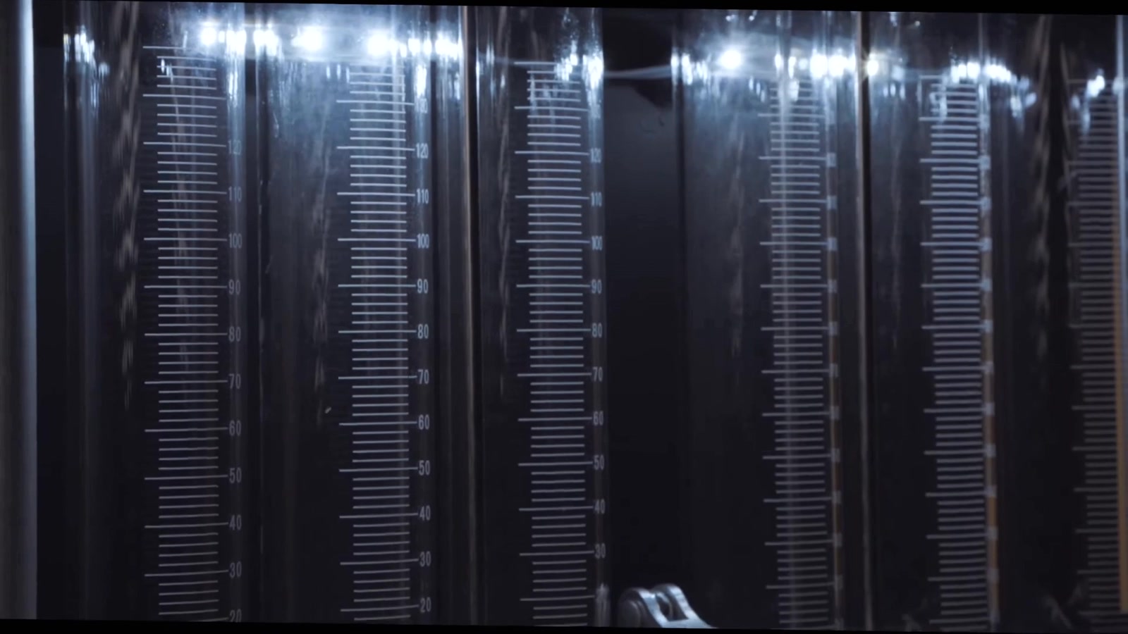
After a completed mode and while the machine is stopped, return pressure to stable zero before operating a cylinder drain or changing the cylinder starting state. Prepare all six measuring positions in the same way, then rerun the selected volume mode under the same recorded conditions.
Let the liquid settle, read every cylinder consistently and record injector, channel and level together. Relative balance is meaningful only within that matched run. The cylinder capacity is not a target, and no single percentage applies to every injector family.
Completion check: Every reading belongs to one traceable injector/channel and one matched set of test conditions.
Step 13: Repeat before attributing an abnormal result
If one result differs, repeat the same test without changing settings. At stable zero pressure and with power isolated, inspect that injector’s seal, adapter, rail position, plug, signal lead, cylinder and drain. If the exact setup permits it, swap the injector with another channel known to work consistently, rebuild the pressure boundary and repeat again.
Interpret the movement of the result:
- If the abnormality follows the injector under matched conditions, the injector remains suspect and should be judged against its exact service limits.
- If the abnormality stays with the machine channel, inspect the adapter, seal, lead, cylinder, drain and channel before condemning the injector.
- If every injector changes together, recheck the common pressure, fluid, mode, pulse/time/count, mounting and test procedure.
An improved before-and-after balance can show that cleaning reduced a restriction. It does not prove that the injector is electrically and mechanically sound or that an on-vehicle fault is repaired.
Completion check: The result has repeated under matched conditions, any fixture or channel cause has been checked, and the final decision uses the exact injector service limits rather than appearance alone.
Phase D: return the machine to a safe state
Step 14: Reach stable zero pressure before disassembly
Use this order at the end of every pressure-side operation:
- Press
Stop. - Use
Decrease Pressurewhile watching the pressure gauge. - Wait until the gauge is stably at zero rather than merely passing through zero.
- Turn the side mains switch off and unplug with dry hands.
- Only now operate the intended cylinder drains, test-fluid recovery route or pressure-side connections.
If the gauge will not reach zero or rises again, do not loosen anything. Keep people away from the pressure area, isolate electrical power if safe, leave the assembly intact and obtain qualified service.
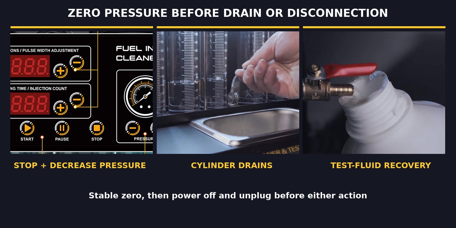
After stable zero and electrical isolation, drain the measuring cylinders into the intended catch area and recover test fluid through its designated route into a compatible labelled container. Do not mix it with cleaning fluid or assume that recovered fluid is fit for reuse. Replace dirty or contaminated test fluid under its instructions.
Remove the injectors without leaning on or side-loading the glass cylinders, then inspect the rail, gauge, hoses, seals, plugs, adapters, drains, leads and cord. Clean and dry the tank and compatible removable parts as their instructions allow. For long storage, remove test fluid as the exact CT200 instructions require and store the machine unplugged, dry, protected from impact and free of cable strain.
Completion check: The gauge is stably at zero, power is disconnected, both fluids are controlled separately, the machine is clean and dry, and every abnormal condition is recorded for correction before reuse.
How to interpret the result
| Observation under matched conditions | What it may support | Next decision |
|---|---|---|
| One injector improves and the set becomes more even after cleaning | Cleaning may have reduced a restriction | Repeat once, compare with the exact service limits and complete any required electrical/on-vehicle checks |
| One injector still drips at the nozzle | Internal sealing wear or contamination may remain | Confirm the fixture has no external leak, repeat and channel-check before service or replacement |
| One injector stays low or has a different pattern | Restriction, damage or an electrical response problem is possible | Repeat unchanged, inspect seals/adapters/leads and perform a safe channel swap |
| The abnormal result stays with one channel | The fixture or machine channel is suspect | Inspect that adapter, seal, signal lead, cylinder, drain and channel; do not condemn the injector |
| Every injector appears weak or inconsistent | A shared setup condition may be wrong | Recheck test fluid, level, pressure, selected mode, pulse/time/count and rail sealing |
| Bench results meet the injector limits but the vehicle fault remains | The fault may lie outside injector delivery | Continue the vehicle maker’s fuel-pressure, electrical, ignition, intake, compression and mechanical diagnosis |
Record the vehicle and injector part number, cylinder and test channel, adapters and seals, both fluid products and lots, mode, pressure, pulse, time or count, before-and-after leakage, spray and volume, repeat or channel-swap result, any abnormal event and the final decision. A complete record is more useful than an undocumented “looks good.”
CT200 troubleshooting and stop rules
| What happens | Safe check after Stop, stable zero and isolation | Do not do |
|---|---|---|
| No display or abnormal startup | Recheck the actual nameplate, matching supply, plug, cord and visible protective-earth condition | Try another voltage, bypass grounding or open the enclosure |
| Ultrasonic cycle does not start normally | Confirm approved fluid is present, menu 01 is selected and the current panel instructions are being followed |
Run the tank dry, use a heating/second-switch instruction or touch the energized bath |
| Test pressure will not build | Check test-fluid level marks, intended plugs, rail alignment, adapters, seals, drains and visible external leaks | Keep increasing pressure, improvise a plug or open the pump |
| Pressure is unstable or will not return to zero | Press Stop, use Decrease Pressure and keep the assembly intact |
Loosen any rail, injector, plug, hose, fitting or drain |
| Fluid leaks outside the intended cylinder path | Stop, decrease to stable zero, isolate and inspect the exact leaking joint | Tighten, wipe or catch a leak while pressurized |
| One cylinder differs from the others | Repeat unchanged, then inspect the fixture and use a supported channel swap | Declare the injector failed from one run |
| An injector does not respond | At zero/isolation, verify compatibility, connector and approved adapter lead | Apply uncontrolled battery voltage or force a connector |
| Glass is cracked, chipped, loose or moving | Stop, return to zero if safely possible, isolate and keep the area clear | Continue the run or press on the glass/rail |
| Smoke, unusual odor, hot wiring or fluid at electrical parts | Isolate power from a safe point, leave the pressure system assembled and obtain service | Approach through spilled fluid, restart or open the case |
Faults involving internal electrical parts, the pump, gauge, pressure controls, glass mounts, cord or protective earth require qualified service, as does any persistent leak. Do not substitute an unspecified fuse or bypass a safety part.
Frequently asked questions
Can the CT200 test GDI or other high-pressure injectors?
No. This CT200 workflow is for compatible standard gasoline port injectors. GDI, FSI and other high-pressure injectors require equipment and procedures approved for their pressure and electrical systems.
Can it clean or test diesel injectors?
Do not use this tutorial for diesel injectors. This workflow does not establish a safe diesel wettable boundary or operating method, and CT200 is not a diesel test bench.
Does the CT200 heat the ultrasonic tank?
This current CT200 workflow uses no heat. Use the single side mains switch, select 01 Ultrasonic Cleaning, set the injector/fluid-approved time and press Start. If another document shows a heating switch, do not apply that instruction to this current layout.
Can I use alcohol, gasoline or another easy-to-find solvent?
Do not use an improvised liquid. Use a purpose-made ultrasonic injector-cleaning fluid in the cleaning tank and a purpose-made injector test fluid in the pressure circuit, with compatibility and SDS controls for each.
How much liquid, pressure, pulse width or time should I use?
Use the delivered CT200 marks plus the exact injector, vehicle and fluid instructions. Capacity and control ranges are not fill targets or universal settings. If the required value is unknown, do not guess.
Can I test only one injector?
Yes, when that exact injector and adapter arrangement are supported and all five unused test positions are closed with the intended supplied plugs and intact seals. Prove the assembly leak-free before running an observation.
Can I use Reverse Flush or No-Disassembly Cleaning?
Not from this guide alone. Use either optional workflow only when you have the exact compatible accessories and a complete procedure for your CT200 revision and injector or vehicle. Their adapters, connections and pressure boundaries differ, so do not improvise from the function name.
What if my CT200 has a pressure knob instead of buttons?
Stop and follow the manual for that exact hardware revision. This guide’s pressure instructions are for the current layout with Increase Pressure and Decrease Pressure controls.
The real result is a repeatable comparison and a safe closeout
A well-run CT200 session keeps every injector identifiable, every test variable controlled and both liquids in their own circuits. It proves the rail is externally leak-free, records leakage, spray and volume under matched conditions, checks an abnormal result against the fixture or channel, and compares the result with the exact injector limits.
The job is not complete when the display stops. It is complete when the pressure gauge is stably at zero, the machine is unplugged, both liquids are separately controlled, the CT200 is clean and dry, and the evidence is strong enough to support the next service decision without claiming more than the bench actually showed.



Comments 0
Questions, fixes, and real-world diagnostic notes from readers.
Be the first to share a diagnostic result or ask a follow-up question.