
How to Use the AUTOOL ATL-3.6SU Scissor Lift: A Safety-First Operator Guide

The AUTOOL ATL-3.6SU is a short-platform scissor lift with a published rated capacity of 3,600 kg. Its safe normal cycle is not simply “press UP, then press DOWN.” First pass the pre-shift check, plan the vehicle-maker lifting points, bring every approved support pad into full contact, and pause at low height to verify clearance, balance, and synchronized movement. Raise to the required height, use LOCK so both safety jaws carry at the same rack level, complete the work, clear the entire travel zone, raise slightly, confirm both jaws release during the trained DOWN sequence, and watch both platforms to full down.
Only trained and authorized personnel should operate this lift. Treat professional installation, commissioning, handover, and identification of the delivered controls as prerequisites. If a support pad moves, the vehicle tilts, the platforms move differently, the two jaws do not lock or release together, or the lift leaks or responds abnormally, stop and keep everyone outside the scissor area.
Last reviewed: August 26, 2026.
What this guide covers—and what it does not
This page explains the normal operating cycle for an ATL-3.6SU that has already been professionally installed, commissioned, and handed over. It focuses on the decisions an operator can observe: whether the bay passes inspection, whether the vehicle and lift fit each other, whether every support point is fully contacted, whether the two platforms move together, and whether both safety jaws reach the correct state before anyone works below or lowering continues.
It is not an installation or service manual. The published documents contain conflicting air-pressure and hydraulic-oil statements. Those values affect installation and service, so this article does not select a number. The delivered pneumatic specification, installed equipment, current service information, and written installer or supplier confirmation govern.
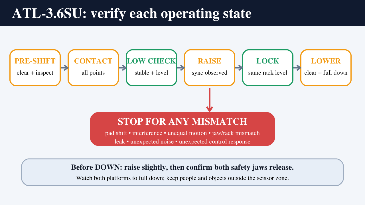
This is also not a universal lifting-point guide. The support points are vehicle-specific. Use current vehicle-maker service information and the approved support devices supplied or specified for the lift. A diagram on this page explains operating states; it does not provide pad coordinates.
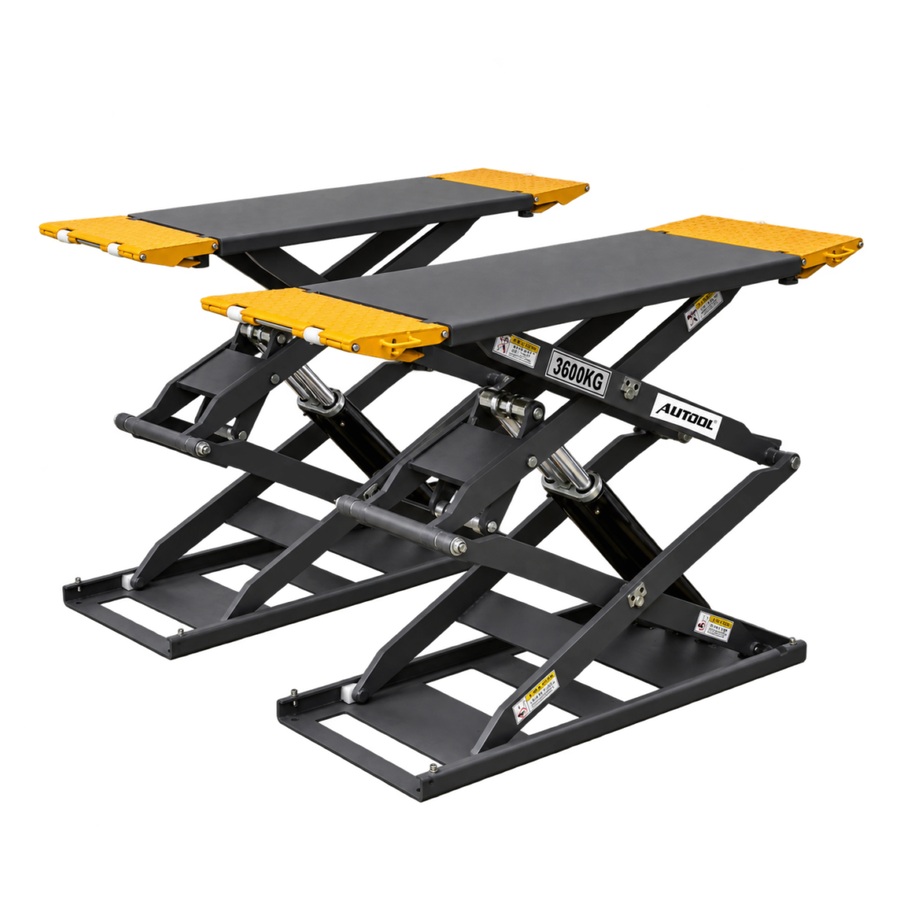
The exact product view shows two low platforms with scissor mechanisms, movable approach ramps/extensions, support blocks, cylinders, and a separate control unit. Identify those parts on the delivered lift from outside its travel zone. Do not use the image to infer an installation dimension or included option.
In this guide
- Before the first operating cycle
- Screen the vehicle and support fit before motion
- Pre-shift check: use a pass/fail gate
- Step-by-step: the normal ATL-3.6SU operating cycle
- Stop-work conditions: do not turn them into DIY troubleshooting
- Verify your delivered ATL-3.6SU configuration
- Is the ATL-3.6SU the right scissor lift for the job?
- The verified state sequence is the operating skill
Before the first operating cycle
Do not treat “the control unit powers on” as a completed handover. Before the first vehicle enters, confirm all of the following:
- The product label identifies the delivered unit as ATL-3.6SU, and its nameplate rating and supply match the order documents.
- A qualified installer has completed the site work, installation, commissioning, safety checks, and required load testing for this exact unit.
- The current, order-specific operating information is available at the lift.
- You can identify
UP,LOCK,DOWN, stop, and power-isolation controls from the installed labels and operator training. - You understand which motion continues only while a control is held and what happens when it is released.
- The delivered pneumatic safety-jaw release has been commissioned to the written specification for this unit.
- You know whether optional infrared leveling or foot-protection devices are fitted and how their normal indication was demonstrated during handover.
- The supplied pads, blocks, ramps, and extensions have been identified, inspected, and approved for the intended task.
If any answer is uncertain, pause before operating. A product-page specification cannot safely complete an incomplete handover.
The nameplate capacity is not a universal vehicle approval
The manual and current product pages consistently publish a 3,600 kg rated capacity, 110 mm minimum platform height, 1,480–2,090 mm platform length, 630 mm platform width, and 1,880 mm lifting height. These figures can help screen a possible fit. They do not prove that a specific vehicle can be lifted.
The controlling questions are more detailed: What is the vehicle’s actual weight and distribution? Where are its manufacturer-approved lifting points? Can all required points sit fully on the approved pads or blocks? Will the chassis, battery enclosure, exhaust, sill trim, or another underbody feature contact a platform or ramp? Does the center of gravity remain between the two support lines? Will removal of a heavy component change that balance?
Do not lift one side only. Do not assume that a vehicle is suitable merely because it is lighter than 3,600 kg or because its tires fit around the platforms.

Screen the vehicle and support fit before motion
Short-platform scissor lifts require a contact plan before the operator raises the vehicle. Use this sequence:
- Obtain the current lifting-point information for the exact vehicle and task.
- Identify every required contact point and the approved pad or block for it.
- Check the vehicle’s weight, distribution, wheelbase, underbody clearance, and any low or fragile component.
- Position the two platforms and movable ramps/extensions only within the delivered instructions.
- Confirm that each support device will sit fully on a load-bearing platform or approved extension area.
- Confirm that the vehicle’s center of gravity will remain between the two support lines.
- Reassess the plan before removing or installing an engine, axle, battery pack, or other heavy assembly.
The manual says the movable ramps can act as load-bearing extension boards, but that is not approval for every long-wheelbase vehicle. An extension is usable only when the delivered equipment permits it and the full vehicle, lifting-point, pad, chassis-clearance, and center-of-gravity check passes.
Support-state gate: Every required point must be centered and fully supported. Stop for an off-center pad, a pad sitting partly beyond its approved bearing area, underbody interference, vehicle tilt, or any change in the planned center of gravity.
Pre-shift check: use a pass/fail gate
Perform this inspection before a vehicle enters. The result is binary: every item passes, or the lift remains out of service.
1. Clear the entire movement and shear zone
Remove tools, hoses, cords, stands, parts, debris, oil, and grease from both platforms, below the vehicle, around the scissor arms, and along the full upward and downward path. Keep customers, bystanders, and non-operators outside the work area.
The space between crossed arms, platforms, the floor, ramps, and the vehicle changes during movement. Never use a hand or foot to guide a platform, ramp, pad, or obstruction while the lift is moving.
2. Inspect visible load-bearing and safety parts
Check the platforms, ramps/extensions, rubber pads or blocks, scissor arms, pivot areas, safety racks, safety jaws, cylinders, and visible fasteners. Nothing should appear cracked, bent, loose, missing, displaced, excessively worn, modified, or contaminated.
Inspect accessible hydraulic hoses and areas for visible damage or leakage from a safe position. Do not loosen a connection or open a pressurized component.
3. Check controls, labels, and fitted options
Control labels and safety warnings must be present and legible. A safety device may not be bypassed. If the unit has optional leveling or foot-protection devices, verify the normal indication or response established during handover. An optional device that is installed but not operating normally fails the gate.
4. Perform the trained no-load function check
With the platforms empty and the zone clear, use the installed controls demonstrated during handover. The platforms should begin raising while UP is commanded, stop when the control is released, and remain synchronized. At a suitable low test position, verify normal safety-jaw/rack behavior. Use LOCK as trained to verify that both jaws can bear at the same rack level. Raise slightly to unload them, then verify that both release during the trained DOWN sequence and that the platforms lower together under continuous observation.
Pass condition: The area is clear; visible parts are intact; no leak is present; controls behave as trained; and both platforms raise, stop, lock, release, and lower together. Unexpected noise, motion, delay, leakage, or a left/right mismatch takes the lift out of service.
Step-by-step: the normal ATL-3.6SU operating cycle
Step 1: Assign one trained operator and clear the zone
One authorized operator should control the vehicle-positioning and lift decisions. Wear the protective equipment required by the supplied instructions and workshop risk assessment. Establish the exclusion zone before the vehicle approaches, including the areas beside, beneath, and between the scissor mechanisms.
Completion check: The operator can see the vehicle, both platforms, and the surrounding work area without entering the travel zone.
Common mistake: Several people approach the vehicle to correct a pad while the lift can still move. Stop motion, isolate the control as required, and keep one operator responsible for the state change.
Stop: Do not begin if the area cannot be controlled or the operator’s view is blocked.
Step 2: Plan the lifting points and balance
Consult the current vehicle-maker lifting information before positioning the vehicle. Mark the required points mentally or by the shop’s approved process, select the correct support pads or blocks, and check the vehicle’s actual weight and load distribution.
Plan for the task, not only the starting vehicle. If a heavy component will be removed or installed, use an approved auxiliary-support and stability plan before lifting.
Completion check: Every required lifting point, support device, and expected center-of-gravity change is known.
Common mistake: Using a generic four-corner pattern from another vehicle. Similar-looking sills can have different reinforced points and underbody hazards.
Stop: Do not continue if the lifting points, weight, distribution, or support method is uncertain.
Step 3: Set the platforms and ramps for the verified fit
With the lift fully down and isolated from unintended motion, position the platforms and movable ramps/extensions only as allowed by the delivered instructions. Check that every pad will remain fully supported and that no platform or ramp can contact an unapproved part of the vehicle.
Do not place a loose object under an extension to change its height or bearing. Do not treat the ramp as an extension unless the supplied configuration and vehicle fit support that use.
Completion check: Platform and ramp positions match the support plan, all intended bearing areas are available, and the vehicle has a clear approach.
Common mistake: Extending a ramp to “reach” a lifting point while leaving part of a pad unsupported.
Stop: Replan if a required point cannot sit fully on an approved bearing surface.
Step 4: Position and secure the vehicle
Move the vehicle slowly over the fully lowered lift as established during handover. Align it with the two platform/support lines and stop at the planned position. Apply the parking brake, switch off the vehicle under the workshop procedure, and have every occupant exit.
Check ground clearance and underbody proximity from outside the movement zone. Do not crawl beneath an unsupported vehicle to inspect a hidden point.
Completion check: The vehicle is stationary, centered for the support plan, occupants are out, and the underbody is clear of unintended platform/ramp contact.
Common mistake: Centering by tire position alone. On this lift, the controlling relationship is between the vehicle-maker points and support pads.
Stop: Move the vehicle away and replan if alignment or clearance cannot be verified safely.
Step 5: Position every approved support pad
Place the supplied or otherwise approved rubber pads/blocks so they contact the exact vehicle-maker lifting points. Keep each pad centered on its approved platform or extension bearing area. Use only pad stacking or adapter combinations permitted for the delivered lift and vehicle.
Walk around the outside of the lift. Check all required points before commanding motion.
Completion check: Every pad is correctly oriented, centered, stable, fully supported, and aligned with its intended vehicle point.
Common mistake: Accepting three good contacts and one marginal contact. The lift does not pass until every required point is correct.
Stop: Do not use a body edge, floor seam, trim panel, battery enclosure, or other unapproved surface as a lifting point.
Step 6: Raise only to a low check height
Return to the operator position. Confirm that every person is clear, then hold the installed UP control while watching the vehicle and both platforms. Raise only enough for all pads to take the vehicle’s load and the tires to begin clearing the floor.
Release the control. The platforms should stop. Keep everyone outside the space beneath the vehicle.
Completion check: All pads remain centered and fully in contact, the vehicle is level and stable, no underbody part is trapped, and the two platforms have moved together.
Common mistake: Raising directly to full work height before contact errors become obvious.
Stop: Lower safely and reposition for any pad movement, vehicle tilt, chassis interference, unequal platform motion, unexpected noise, or leak.
Step 7: Verify the low-height state from all safe viewing positions
Inspect each support relationship from outside the movement zone. Confirm the vehicle has not shifted, every pad is carrying as planned, the ramps/extensions remain correctly seated, and the center of gravity remains within the two support lines.
Do not push, rock, or enter beneath the vehicle as a “stability test.” The low-height check is visual and procedural.
Completion check: All contacts, clearances, and platform movements match the approved plan with no warning sign.
Common mistake: Looking only at the easiest visible side. Check every required point from a safe viewing position.
Stop: If any point cannot be verified, lower fully and correct the setup; do not continue on an assumption.
Step 8: Raise to the required work height
Hold UP and observe both platforms, the vehicle, the pads, the scissor zones, and overhead clearance throughout movement. The manual describes UP as a hold-to-run control; releasing it should stop rising on the delivered configuration.
Use only the height needed for the task. Do not allow a person to enter the vehicle or the lift area during movement.
Completion check: Both platforms remain synchronized, the vehicle remains stable and clear, and the lift stops normally at the chosen height.
Common mistake: Watching the control panel instead of the moving equipment.
Stop: Release the control immediately for tilt, unequal motion, pad shift, interference, jerking, an abnormal sound, leakage, or an unexpected response.
Step 9: Put both safety jaws on the same rack level
At the selected height, use the installed LOCK control as demonstrated during handover. The platforms should lower into a mechanically supported working state while the safety jaws remain available to engage the racks.
Verify from safe positions that the safety jaw on each platform bears at the same rack level. Do not infer this state from a sound alone.
Completion check: Both jaws are carrying at the same level, the platforms are stable and synchronized, and the vehicle has not shifted.
Common mistake: Leaving the working load supported only by hydraulic pressure above the racks.
Stop: Keep everyone out if one jaw fails to bear, the levels differ, or a platform changes position. Follow the trained safe-lowering/isolation procedure and call qualified service; do not adjust the jaw, rack, cylinder, or pneumatic system.
Step 10: Work without changing the balance assumption
Maintain the exclusion-zone and workshop communication controls. Do not let anyone enter the vehicle, rock it, bypass a safety device, or create an unplanned one-sided load.
Before removing or installing a heavy part, verify the approved support plan again. The lift’s mechanical locks support the platforms; they do not prevent the vehicle from becoming unstable on its pads.
Completion check: The vehicle, all support contacts, and both locked platforms remain in the planned state throughout the work.
Common mistake: Assuming a locked lift makes any component-removal sequence safe.
Stop: Stop work for vehicle movement, a changed support state, a shifted auxiliary support, or an unplanned center-of-gravity change.
Step 11: Clear the entire lift before lowering
Finish the work and account for every person, tool, part, hose, cord, stand, and support device. Confirm the vehicle is complete and stable enough to lower. Clear the space under, beside, above, and between the platforms and scissor arms.
Return to the operator position with a full view. Do not place a hand, foot, block, or tool near a platform or arm to guide the descent.
Completion check: Nothing intersects the downward path and every person is outside the movement zone.
Common mistake: Checking only the area directly beneath the vehicle while leaving an obstruction beside an arm or under a ramp.
Stop: Do not move the lift until the entire travel zone is clear.
Step 12: Unload and release both safety jaws
Use UP only long enough to raise the platforms slightly and remove the load from the safety jaws. Then use the installed DOWN control as trained. The manual describes pneumatic release of the jaws during descent.
Confirm that both jaws release and both platforms begin lowering together. Do not continue if one remains engaged.
Completion check: Both jaws are clear of their racks and the platforms remain synchronized at the start of descent.
Common mistake: Commanding descent while the jaws are still loaded, or assuming one released side proves both released.
Stop: If either jaw fails to release or one platform responds differently, stop. Do not force, strike, bypass, or adjust the mechanism.
Step 13: Lower fully under continuous observation
Continue using DOWN according to the installed hold-to-run behavior and training. Watch the vehicle, pads, platforms, ramps, scissor arms, and surrounding area until the lift reaches its fully lowered state.
Keep feet, hands, clothing, tools, and bystanders outside the changing pinch and shear zones. The vehicle should remain stable as its tires return to the floor and the pads unload.
Completion check: Both platforms are fully down and stopped, the vehicle is stable on the floor, and the support pads are unloaded.
Common mistake: Turning away when the tires are nearly down. Continue observing until all motion stops.
Stop: Stop for unequal descent, unexpected re-engagement, an obstruction, jerking, leakage, abnormal noise, or a control that does not respond as trained.
Step 14: Remove the vehicle and close out the cycle
Only after the lift is fully down should you remove or stow the support pads as required and move the vehicle away slowly. Confirm the path is clear and no ramp, platform, tool, or person is in the vehicle’s path.
Return the lift to its specified full-down storage state. Switch off or isolate power under the workshop procedure. Record and report any abnormality noticed during the cycle, even if movement was completed.
Completion check: The vehicle is clear, the lift is fully down and powered down as required, the bay is orderly, and defects have been reported.
Common mistake: Moving the vehicle before pads and low platforms are confirmed clear.
Stop-work conditions: do not turn them into DIY troubleshooting
Stop motion, keep people outside the lift area, and use the trained emergency or isolation procedure for the installed unit if any of these conditions occurs:
- A pad moves, sits off-center, loses full bearing, or contacts an unapproved vehicle surface.
- The vehicle tilts, slips, rocks, touches a platform/ramp unexpectedly, or no longer matches the planned center of gravity.
- One platform raises, stops, locks, releases, or lowers differently from the other.
- The two safety jaws do not bear at the same rack level or do not release together.
- A platform, ramp, arm, pivot, rack, jaw, pad, hose, cylinder, control, label, or safety device appears damaged, loose, missing, modified, or bypassed.
- You see a leak or hear/feel jerking, delay, an abnormal sound, or an unexpected control response.
- A fitted optional protection or leveling device no longer behaves as demonstrated.
- A person or object enters the movement, pinch, or shear zone.
Do not enter beneath a vehicle unless both platforms are confirmed mechanically supported at the same level. Do not open the control unit, loosen a hydraulic or pneumatic connection, change the oil or air setting, adjust synchronization or safety parts, or improvise an emergency descent from this article. Tag the lift out under the site procedure and contact qualified service.
Verify your delivered ATL-3.6SU configuration
Use this table before first operation, after a document change, or before ordering. The purpose is to identify the controlling record for the exact unit—not to choose a convenient web value.
| Item | Why it matters | What to verify |
|---|---|---|
| Pneumatic supply | The current product pages and manual publish different pressure ranges. | Delivered pneumatic specification, installed regulator/supply, commissioning record, and written supplier or installer confirmation. |
| Hydraulic oil | The manual contains multiple grade and quantity statements. | Current order/serial-specific service information and qualified service procedure; no operator filling decision from this page. |
| Controls and jaw release | Safe lowering depends on unloading and releasing both jaws. | Installed labels, hold-to-run behavior, handover demonstration, and the exact UP–LOCK–DOWN sequence. |
| Optional infrared/foot protection | Current pages list these as optional, not universal. | Which options are physically installed and their normal indication and stop response. |
| Ramps/extensions | They may be load-bearing extensions, but fit is vehicle-specific. | Delivered instructions, full bearing, lifting-point reach, chassis clearance, and approved pad/extension combination. |
| Vehicle envelope | Published capacity and geometry are screening data only. | Actual weight/distribution, lifting points, wheelbase, underbody clearance, platform contact, and center of gravity. |
| Installation and load test | A product claim is not a commissioning record. | Site-specific installation acceptance, safety checks, load-test documentation, operator training, and service contact. |
Is the ATL-3.6SU the right scissor lift for the job?
The AUTOOL ATL-3.6SU may suit a professional workshop that needs low-profile access and an open area around much of the vehicle. It is suitable only when the specific vehicle can make correct support contact and the site, installation, controls, training, inspection, and service plan are all verified. If you purchase through that model link, OBD2SCAN may receive a commission.
Before ordering, complete this fit check:
- Record the heaviest vehicles, real load distribution, wheelbase range, ground clearance, underbody hazards, and manufacturer lifting-point span.
- Verify that every required point can sit fully on an approved pad and supported platform/ramp position.
- Confirm the current site/floor or recess design, electrical and pneumatic requirements, travel clearances, traffic flow, and local requirements with qualified parties.
- Obtain a written delivered-configuration list for controls, pads/blocks, ramps/extensions, optional sensors, power unit, documentation, and safety equipment.
- Confirm professional installation, commissioning, load testing, operator training, daily inspection responsibility, service coverage, and parts availability.
Confirm the delivered configuration in writing before treating any product-page image or value as final.
The verified state sequence is the operating skill
Three gates control the ATL-3.6SU cycle: every vehicle-maker lifting point has full approved support contact; the low-height check confirms stable, clear, synchronized movement; and both safety jaws are verified at the same rack level for work, then unloaded and released together before lowering.
At the end, both platforms are fully down, the vehicle is clear, power is handled under the site procedure, and any abnormality is recorded. If the vehicle fit, delivered controls, pneumatic requirement, optional equipment, jaw behavior, or support plan is uncertain, pause and obtain qualified written confirmation rather than experimenting.




Comments 0
Questions, fixes, and real-world diagnostic notes from readers.
Be the first to share a diagnostic result or ask a follow-up question.