
How to Use the MRCARTOOL F118 Brake Fluid Exchanger

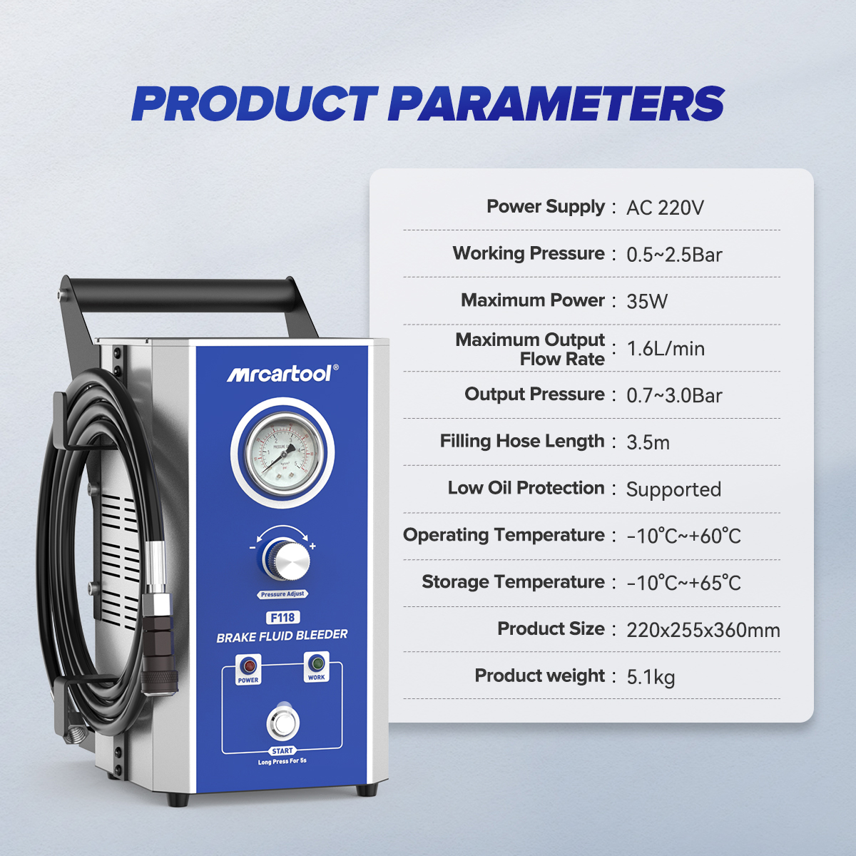
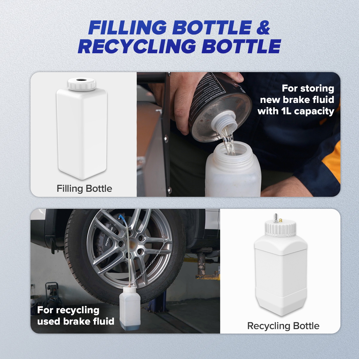
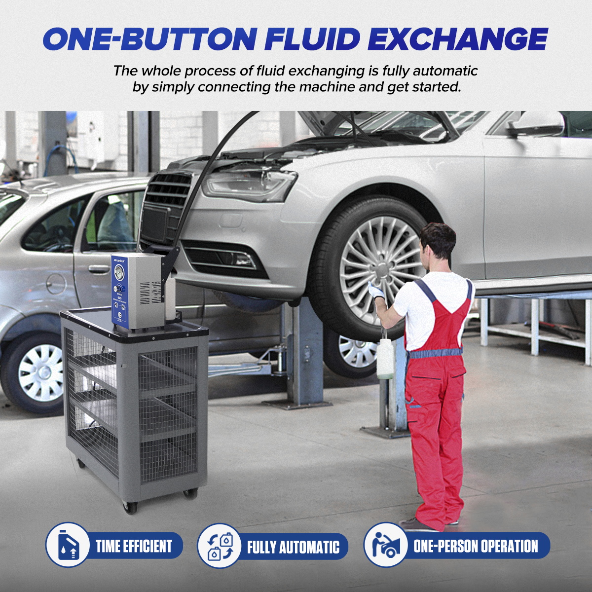
The MRCARTOOL F118 brake fluid exchanger is a DC 12 V pulsating-pressure machine with a 3.5 m filling hose, a fresh-fluid bottle, a wheel-side recovery bottle and seven reservoir adapters. It feeds new fluid through a sealed reservoir adapter while the operator drains old fluid at each service point. The reliable sequence is simple but strict: identify the vehicle procedure, prepare enough correct fluid, prime the machine into the recovery bottle, choose Standard or Fast mode only while power is off, connect the exact adapter, verify the seal, then bleed one prescribed point at a time.
Quick answer: Place F118 on a level surface. Fill its rear bottle with new, unopened brake fluid of the exact vehicle specification and put both the suction and pressure-balance hoses at the bottom. Attach an adapter to the filling hose and point it into the recovery bottle. Connect red to battery positive and black to negative, select Standard mode while power is off, switch on and press Start until the outlet is bubble-free. Press Stop. Install the correct adapter on the clean vehicle reservoir, connect the hose, choose the vehicle-approved pressure mode while powered off, then press Start. Inspect the seal before opening any bleeder. Follow the vehicle’s order, close every bleeder before moving on, press Stop, disconnect safely, set the final level and pass all brake checks.
In this guide
Know the F118 controls and limits
The exact F118 manual specifies DC 12 V battery power, 35 W maximum power, 1.2 L/min maximum flow, noise at or below 70 dB and a 3.5 m filling hose. Standard mode operates at 1.5–2.0 bar; Fast mode operates at 2.0–2.5 bar. These are machine modes, not universal vehicle permissions. The manual repeatedly makes the vehicle manufacturer’s maximum filling pressure and special instructions controlling.
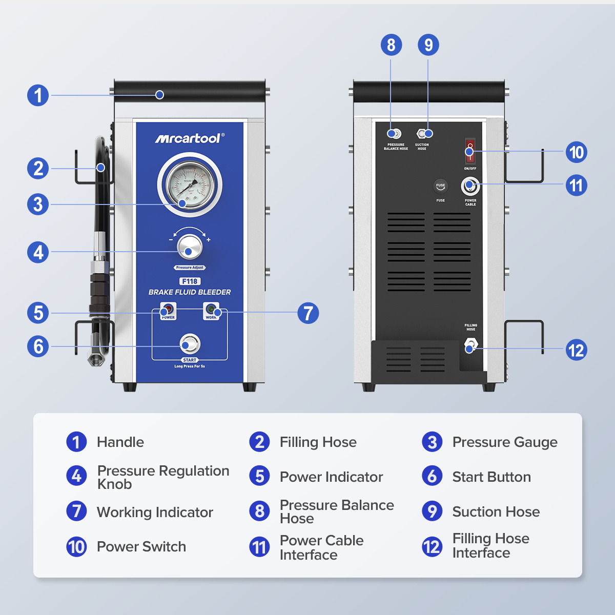
The front panel has a pressure gauge, Standard and Fast mode indicators, Power and Working indicators, plus Start and Stop switches. The rear carries the power switch, fused DC input, filling-hose output, suction hose and pressure-balance hose. Learn those paths before adding fluid. Confusing the supply and balance hoses, powering with reversed polarity or treating Stop as a pressure-setting control can interrupt the exchange or introduce air.
Brake hydraulics are safety-critical. The manual limits F118 to trained professionals and to brake fluid in automotive brake and clutch systems. Wear splash goggles and compatible gloves, protect paint and electrical parts, keep the machine dry, support the vehicle correctly and stop if the specified fluid, pressure, adapter, sequence or final test is uncertain.
Prepare the machine and vehicle
- Record the vehicle’s exact brake fluid, maximum pressure, service-point order, reservoir adapter and any required ABS, clutch or pedal routine.
- Inspect the F118 housing, handle, gauge, hose hook, filling hose, suction and balance hoses, fuse, cable clips, connectors and bottles.
- Confirm the 12 V vehicle battery is suitable, the ignition state matches the service procedure and red/black polarity is unambiguous.
- Prepare enough sealed correct fluid for priming and the complete exchange, plus a visible reserve; never return recovered fluid to the supply.
- Check for an unexplained low reservoir, leaks, damaged pipes, a soft pedal or warning indicator before treating the job as routine maintenance.
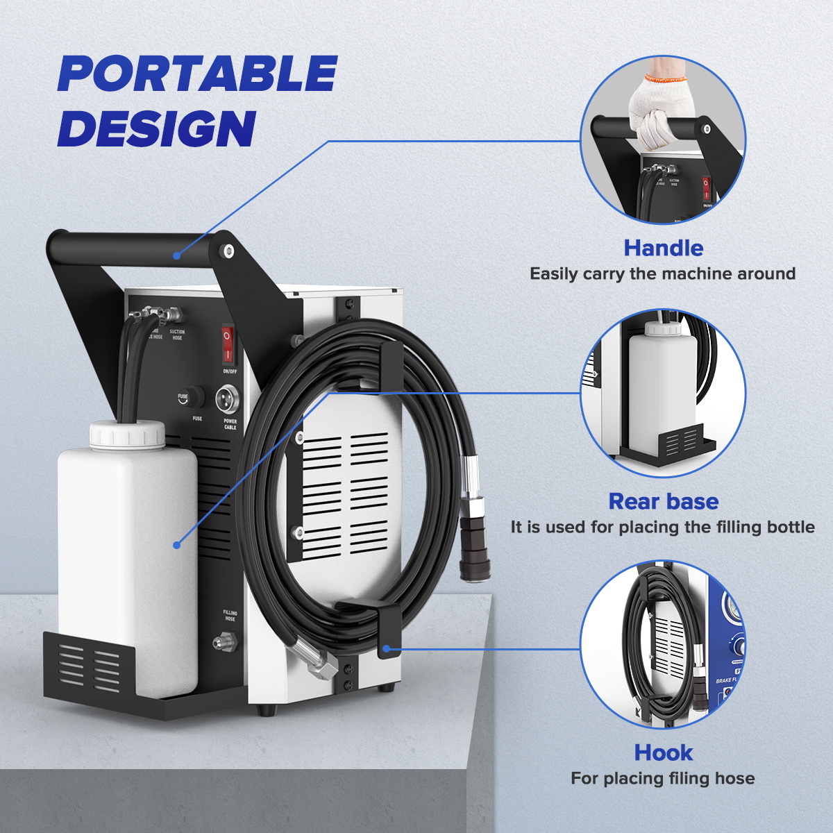
- Position F118 upright on a level dry surface and route its 3.5 m hose so lifting the vehicle cannot stretch, crush or pull the adapter.
Choose the reservoir adapter by fit—not the vehicle list alone
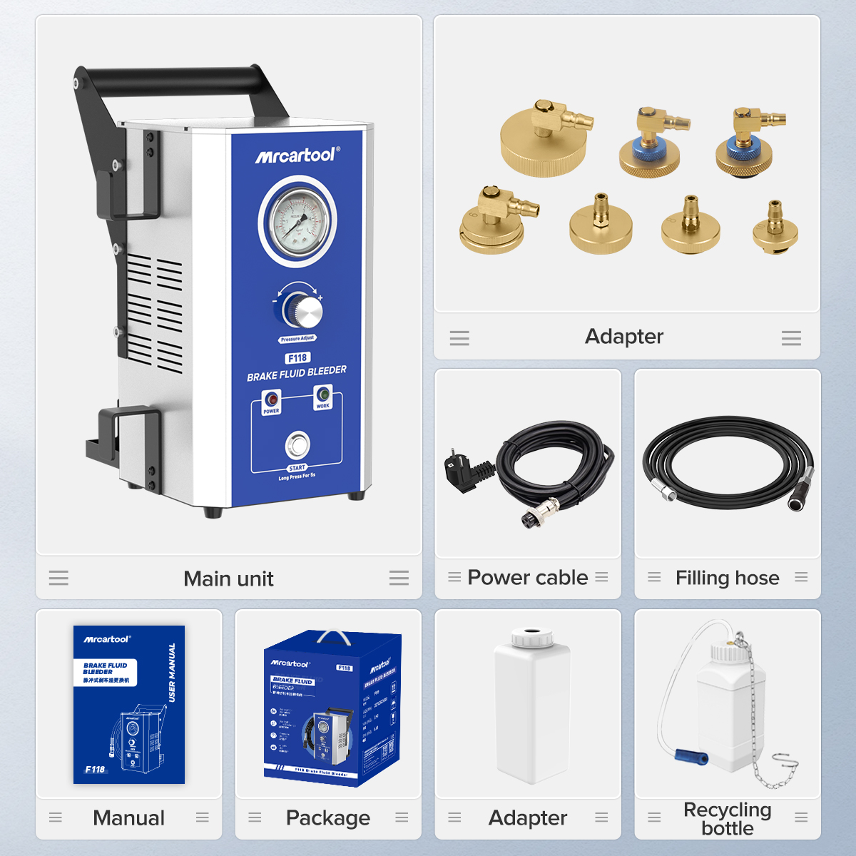
Seven adapters cover multiple reservoir designs. The manual lists broad applications for B01 through B07, but model lists are only a starting point because caps, reservoirs and markets can vary. At zero pressure, dry-fit the proposed adapter squarely on the clean sealing surface. It must seat without cross-threading, rocking, distortion or improvised packing and must resist a light controlled pull. If it does not, stop and source the exact adapter.
Prime the filling path before first use
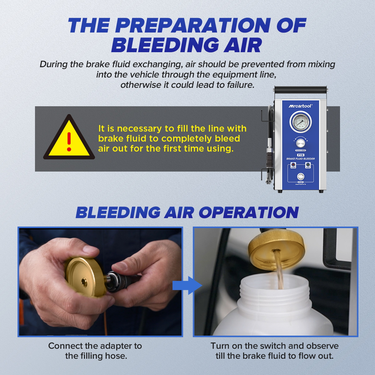
The manual calls this equipment air-emptying and requires it at first startup. It is also prudent whenever the supply path has been emptied, a hose has been opened or visible air is present. Priming must happen into a compatible waste container before the adapter is fitted to the vehicle. That prevents the machine’s initial air volume from being pushed into the master-cylinder reservoir.
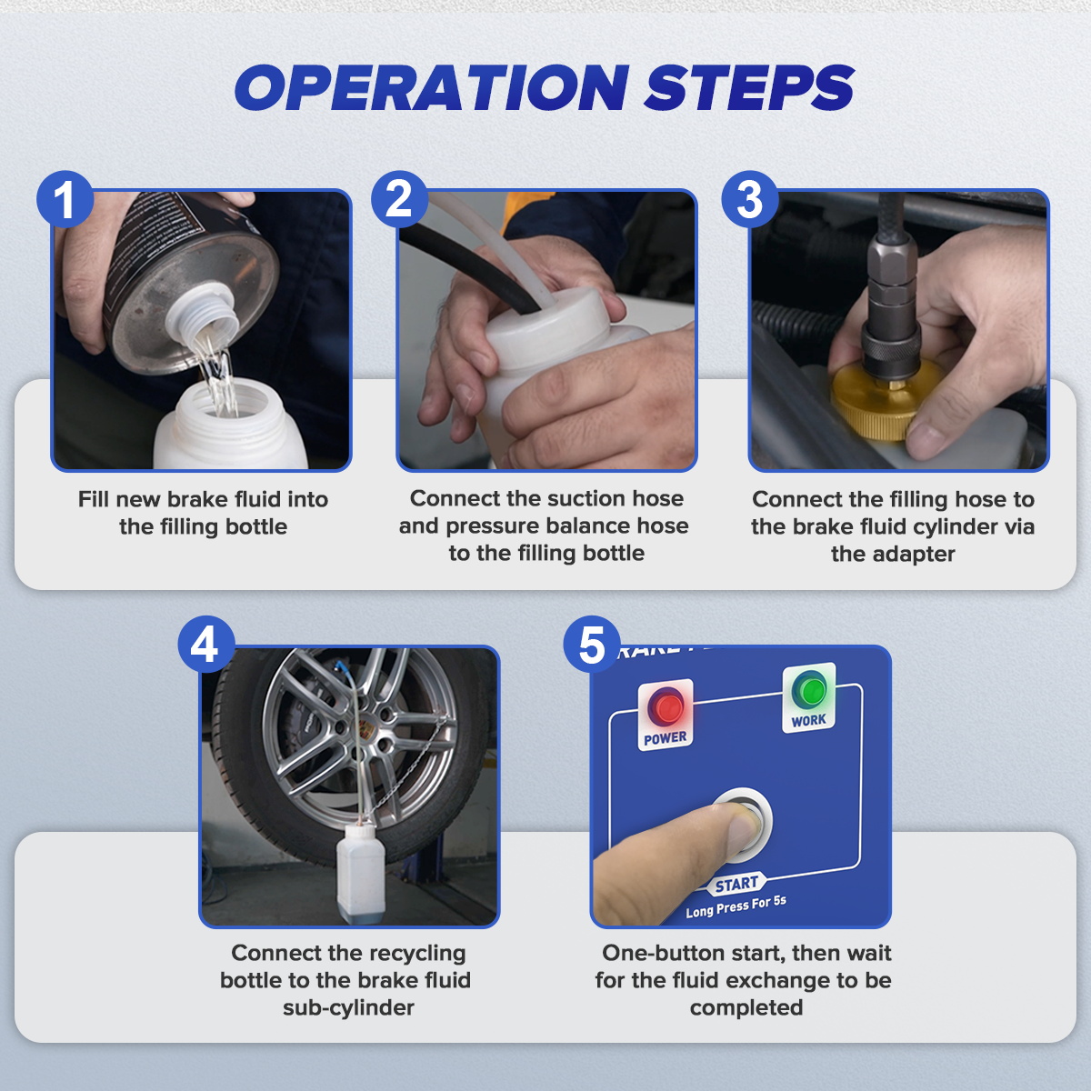
1. Prepare the fresh-fluid bottle
Clean around the filling-bottle cap, open it and add only new fluid matching the vehicle specification. Put the suction hose and pressure-balance hose all the way to the bottom, then place the bottle securely on the rear bracket. The suction hose feeds the pump; the balance path allows the bottle side to function as designed. Keep both ends submerged and watch the reserve throughout the service.
2. Purge into the recovery bottle
Connect the selected reservoir adapter to the filling hose but keep it off the vehicle. Aim and secure it in the recovery bottle. With F118 power off, select Standard mode. Attach the DC clips red to positive and black to negative, turn on the rear power switch and press Start. Continue until brake fluid leaves the filling hose with no visible bubbles. Do not treat a fixed time as proof; the outlet condition is the endpoint. Then press Stop and contain the priming fluid as used waste.
Connect to the vehicle and select pressure
3. Install the adapter at zero pressure
Clean the reservoir exterior so debris cannot enter when its original cap is removed. Install the verified adapter on the intended sealing surface and secure it without excessive force. Connect the primed filling hose to the adapter. Keep the hose supported so its weight and movement do not lever against a plastic reservoir.
4. Select Standard or Fast only while power is off
F118 has two fixed pressure bands rather than a continuously adjustable knob. The manual says the equipment must be powered off when switching modes. Standard covers 1.5–2.0 bar and Fast covers 2.0–2.5 bar. Use the mode allowed by the exact vehicle procedure; never select Fast merely to shorten the job. If the vehicle’s maximum is below the chosen band, F118 is not suitable for that setup unless an approved model-specific method provides the required control.
5. Start and inspect the seal before bleeding
Turn on power and press Start. Watch the pressure gauge and immediately inspect the reservoir adapter, plastic reservoir, filling connector and hose for movement or seepage. The manual says to press Stop immediately if fluid overflows. A pressure that will not establish, a machine that stops, or a falling gauge with all bleeders closed points to low supply, an air-drawing suction hose, a loose connection, adapter leakage or another open path. Correct the cause instead of repeatedly restarting.
Exchange fluid point by point
6. Prepare one used-fluid path
Raise and support the vehicle only as required by the service plan. At the first manufacturer-prescribed point, clean the bleeder, position the correct wrench and attach a snug transparent hose to the recovery bottle. Keep the bottle upright and away from hot brakes, moving suspension and paths where it can be knocked over. Do not let the used-fluid hose or bottle contact the clean adapters or filling equipment.
7. Open, observe, close and move
With the Working indicator on and pressure stable, open only the first prescribed bleeder. Observe the outgoing fluid, bubble pattern, gauge and new-fluid reserve together. Continue to the vehicle-defined endpoint, which may be a specified volume, clean replacement fluid or completion of an electronic routine. Close the bleeder to the required torque before removing the collection hose, wipe the area and inspect for seepage. Only then move to the next point.
Use the exact order in the vehicle information. Although the F118 manual offers a general fallback when no order is stated, modern split circuits and ABS hydraulic layouts vary, so a remembered farthest-wheel rule is not a dependable universal method. If the system has run dry, a hydraulic unit was replaced or air remains trapped, complete the manufacturer’s master-cylinder, scan-tool ABS, pedal or second-pass procedure. F118 supplies fluid pressure; it does not activate valves or prove all air has left the system.
Stop, disconnect and verify
8. Close the hydraulic path before Stop
Close the active bleeder and confirm every other service point is closed. Press Stop, switch off the machine and observe the gauge. Do not loosen the reservoir adapter or quick connector while the line remains pressurized. If pressure does not return safely or a fitting is loaded, follow the exact manual and service procedure rather than using a connector or bottle cap as a pressure-release device.
9. Restore the reservoir
After safe depressurization, disconnect the filling hose and remove the adapter without spilling fluid onto paint or wiring. The manual notes that the reservoir may be full after exchange; use a clean compatible suction tool to set the level within the vehicle’s permitted range. Refit the original clean cap and diaphragm. Inspect every serviced bleeder, the reservoir and any disturbed hydraulic joint for seepage.
10. Pass the brake acceptance gates
With the vehicle stationary, perform the specified pedal-feel and pedal-hold checks and confirm the fluid level and warning indicators. Complete any diagnostic routines. Reinstall wheels and torque fasteners when removed. A qualified operator may then conduct the prescribed low-speed brake check in a controlled area. A soft, sinking or inconsistent pedal, visible loss, warning lamp, unusual pull or unequal braking is a no-drive result until the cause is corrected.
Troubleshooting
| Symptom | Check first |
|---|---|
| No bubble-free flow while priming | Correct fluid, both bottle hoses submerged, tight clean-side fittings, Standard mode and DC polarity |
| Pressure will not establish | Supply level, suction hose, adapter seal, filling connector, open bleeder and visible leakage |
| Fluid overflows at the reservoir | Press Stop; inspect adapter fit, reservoir condition and selected pressure mode |
| Mode will not change correctly | Power the machine off before selecting Standard or Fast |
| Machine stops during exchange | Fresh-fluid reserve, suction-hose immersion, battery connection, fuse and leak path |
| No flow at one bleeder | Correct service point, bleeder opening, hose blockage and vehicle-required electronic routine |
| Pedal remains soft | Keep vehicle stationary; inspect leaks, sequence, trapped air and incomplete ABS or pedal procedure |
Final F118 checklist
- Exact fluid, pressure band, adapter, bleed order and electronic routines recorded
- F118, gauge, fuse, clips, bottles, hoses and connectors dry and undamaged
- Fresh-fluid bottle filled and both supply-side hoses submerged
- Filling path primed into recovery bottle until bubble-free
- Correct adapter installed squarely at zero pressure
- Standard or Fast selected only while F118 was powered off
- Pressure stayed inside both the vehicle limit and selected F118 mode
- Each prescribed bleeder was closed and inspected before moving on
- Supply reserve remained visible; used fluid stayed separate
- Machine stopped and line safely depressurized before disconnection
- Final level, cap, pedal, leaks, warnings and controlled brake test passed
For the current control labels, adapter table and operating sequence, select the exact F118 PDF on the MRCARTOOL manual download page before service.
The F118 reduces the need for a second operator, but it does not reduce the need for disciplined control. Prime first, keep the supply visible, choose pressure with power off, inspect the reservoir seal before opening a bleeder and follow the vehicle sequence. Close every hydraulic point before Stop, disconnect only after safe depressurization and release the vehicle only after pedal, leak, warning and controlled brake checks all pass.











Comments 0
Questions, fixes, and real-world diagnostic notes from readers.
Be the first to share a diagnostic result or ask a follow-up question.